patent · US4002421
Control of vertical heat treating vessels
11 January 1977
Page 1 — bibliographic record
United States Patent to 11 4,002,421 Summer 45 Jan. 11, 1977 54 CONTROL OF VERTICAL HEAT TREATING Primaryy Examiner-John J. Camby VESSELS Attorney, Agent, or Firm-Richards, Harris and 75 Inventor: James R. Summer, Blum, Tex. Medlock (73) Assignee: Round Rock Lime Company, Blum, 57 ABSTRACT
Uniform heat treatment of particulate material of non 22 Filed: Mar. 7, 1975 uniform gradation in a vertical heat treating vessel such (2) Appl. No.: 556,282 as a vertical kiln or retort is affected by regulating the heat input to a heat treating zone in the vessel in re
Related U.S. Application Data sponse to changes in specific gravity of the mass of - -- particles passing into the heat treating zone as detected (60) pivision of Ser. No. 467,139, May 6, 1974, Pat. No. by measurements such as differential pressure changes 3. this, S a it. of Ser. No. of combustion supporting fluid and process gas flowing 383,484, July 30, 1973, Pat. No. 3,849,061. into and from the heat treating zone to result in a bal 52 U.S. Cl. ................................... 432/19; 432/36; ance between particulate mass flow and heat input and 432/47 substantially uniformly heat treated particulate mate (5 Int. C.’........................ F27D 7100; F27B 9/40 rial. Furthermore, uniform oxygen conversion within a 58 Field of Search .................. 432/14, 17, 19, 36, heat treating zone in a vertical heat treating vessel is 432/47 maintained by measuring the oxygen content in the o effluent gases passing from the gas outlet of the heat 56 References Cited treating vessel and controlling the flow of air into the UNITED STATES PATENTS heat treating vessel in response to variations of the 2,451,024 101 1948 Ellerbeck 432/17 oxygen content in the effluent stream to maintain a 2,616,678 fig52 Grossman .432/36 x constant oxygen content in the cffluent gas stream. 2,84,479 l l 1957 Leone .............................. 432/36 X 3, 19,605 lf 1964 Berz. .................................... 432/47 3, 185,457 5f 1965 Boll ct al. ............................ 432/36 i5 Claims, 5 Drawing Figures
M -- - --- - --
Cok
o-7 2
42a - Z -AIR
(i), stree dystrip- 66 Case'
Page 2
Drawing sheet — no readable text.
Page 3
Drawing sheet — no readable text.
Page 4
Drawing sheet — no readable text.
Page 5
Drawing sheet — no readable text.
Page 6
Thus, prior art vertical kilns have not provided pre
CONTROL OF VERTICAL, HEAT TREATING cise control of the calcining operation, particularly VESSELS when run on a continuous basis and when the grade and This is a division of copending application Ser. No. size of the limestone charge is changed during the run. 467,139 filed May 6, 1974, now U.S. Pat. No. 5 Since quarried limestone generally has a varying parti 3,884,621, which is a continuation-in-part of applica cle size, for example from about 94 or less to about 2% tion Ser. No. 383,484 filed July 30, 1973, now U.S. Pat. inches or more, it has been extremely difficult to obtain No. 3,849,061. a uniform distribution of solids and treating fluids This invention relates to vertical heat treating vessels. through the burning Zone in the vertical kiln. As a In another aspect, this invention relates to controlled O result, the more reactive limes have been produced by heat treatment of particulate material within a vertical the rotary kilns available in the art. The rotary kilns are vessel. In still another aspect, this invention relates to a extremely thermally inefficient but capable of produc novel calcining process and apparatus. ing a uniformly calcined and active product. Therefore, Vertical heat treating vessels which are commonly the lower grade limes are conventionally produced by known as vertical kilns, shaft kilns, shaft furnaces, or 15 the vertical kilns. Furthermore, lime produced by prior shaft generators, retorts or the like, depending upon art vertical kilns can vary widely in product quality, the type of treatment and the material being treated, because the gradation of the limestone fed to the kiln comprise process equipment commonly found in di generally varies considerably.
verse kinds of industry. Such devices have been used Furthermore, control of proper fuel/air ratios within for burning or calcining lime, coking coal, burning 20 the heat treating or burning zone of vertical heat treat argillaceous and calcareous material in the production ing vessel has been generally difficult to accomplish of cement clinker, burning magnetite, dolomite, retort because of such factors as (1) leakage of air and/or ing oil shale, and the like. Such devices commonly vaporous fuel such as natural gas through the particu include a vertical vessel having an elongated heating late outlet which removes the heat treated particulate shaft therewithin, a means for uniformly feeding a par 25 material from the lower end of the vertical vessel; and ticulate material into the elongated heating shaft, a (2) changes in atmospheric conditions which effect the lower discharge means for removing material from the quantity of gas and air which is fed to the heat treating lower outlet end of the kiln, and a means for introduc zone. More specifically, changes in atmospheric tem ing a stream of heat treating fluid through the particu perature and pressure will substantially affect the num late material. Commonly, these vessels include a means 30 ber of molar equivalents of natural gas and oxygen for introducing a combustible fluid such as a fuel-air which is contained within a metered volume of natural mixture upwardly through the kiln which establishes a gas or air which is passed into the heat treating zone. combustion or burning zone in the middle portion of Consequently, the use of conventional controls for the kiln. Other conventional kilns or retorts utilize a metering these gaseous fluids to the interior of the kiln heat supply system which includes an external combus 35 generally inadequately compensates for atmospheric tion system and means for directing the hot gases from changes.
the combustion system to the burning zone of the kiln. According to one embodiment of the subject inven Problems have been encountered in maintaining a tion, a uniformly controlled oxygen conversion within a uniform downward movement of particulate material fluid comprising a combustion supporting gas and air is throughout the cross sectional extent of the vertical 40 provided within a heat treating zone of a vertical vessel shaft from the top or feed end of the kiln to the lower by constantly measuring the oxygen content of effluent or outlet end of the kiln. As a result, discharge grates gases passing from the burning zone and controlling the such as disclosed in U.S. Pat. No. 3,401,922 have been relative amount of air passed to the burning zone in developed in an effort to solve this problem. Further response to variations in the oxygen content in the more, problems have been encountered in uniformly 45 effluent gas stream to thereby maintain a relatively heat treating the particulate material passing through constant oxygen content in the effluent stream. the kiln, even though the actual speed of the particulate According to another embodiment of the subject mass passing through the kiln can be fairly accurately invention, a method and apparatus are provided for controlled by using discharge grate systems such as heat treating particulate material of nonuniform grada disclosed in the above-cited patent. In general, uniform 50 tion in a vertical kiln by supplying a heat input within a heat treatment of a particulate mass passing through a combustion stream comprising gaseous fuel and air vertical kiln has been difficult to effect because of the which is passed through a heat treating zone of the difficulty of maintaining the required heat input to the vertical vessel, which heat input is sufficient to treat a material passing through the burning zone. charge of average particles which has a predetermined It has generally been difficult to obtain a uniform 55 mass residence time as the charge flows by gravity quality of reactive lime (CaO) from limestone (CaCO3) through the heat treating zone which predetermined feed material with a vertical kiln. Very reactive lime mass residence time is based upon a predetermined (which is reactive to water for hydration) is basically in bulk density and a predetermined flow rate of particles the rhombic crystalline form. Lime in a cubic crystal through the burning zone and thereafter passing the line form is nonreactive to water for hydration. Lime 60 particulate material through the heat treating Zone and stone generally has a rhombic crystalline structure and sensing a quality indicative of the bulk density of the by careful control of the calcining process which in particulate materials passing through the heat treating cludes burning of the limestone and removing CO2 zone and comparing the indicated bulk density with the therefrom, the rhombic crystalline structure of lime said predetermined bulk density and thereafter control stone can be retained in the lime. However, overburn in 65 ling one of (1) the flow of particulate material through a kiln will alter the rhombic crystalline structure of the the heat treating zone and (2) the heat content of fluid product, e.g., change it to cubic form, and therefore, passed to the heat treating zone, relative to the com reduce its chemical activity. pared bulk density to yield a product which has been
Page 7
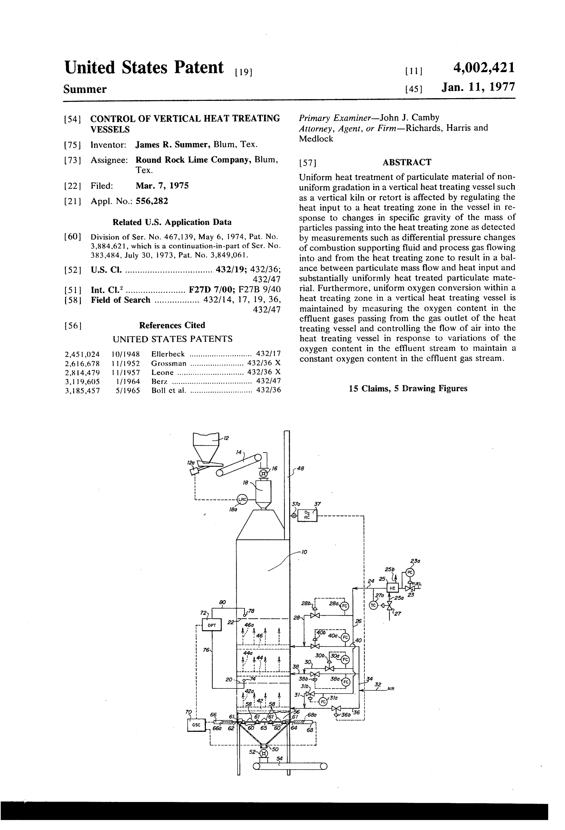
heat treated equivalent to a charge of standard parti inlet to kiln 10 receives solid particulate material such cles having a predetermined bulk density while con as limestone, which is initially delivered from stone stantly sensing the oxygen content of the gaseous efflu storage bin 12 by way of a conveyor 14 through rotary ent from the heat treating zone and controlling the flow seal 16 into hopper 18. Level controller 18a operates of at least one of (l) air and (2) gaseous fuel to the heat discharge control mechanism 12a of storage bin 12. treating Zone in response to variations in the said oxy Vertical kiln 10 is provided with a fuel and air deliv gen content to maintain a substantially uniform oxygen ery system adjacent its lower midportion for delivering content in the effluent stream. a combustible mixture to the burning zone of the kiln. According to still another embodiment of the subject The lower end 20 of the burning zone is schematically invention, particulate materials of a nonuniform grada O depicted by a broken line and the upper end 22 of the tion are heat treated in a heat treating zone of a vertical burning zone is schematically depicted by a broken vessel by regulating the heat input to the heat treating line.
zone in the vertical vessel in response to differential It is noted that a vertical kiln equipped with the con pressure changes a fluid, such as combustion support trol mechanism of the subject invention can utilize any ing fluid and process gas flowing into and from the heat 15 heat supply system known in the art, e.g., external or treating zone to thereby yield a balance between partic internal combustion chambers. As illustrated in this ulate mass flow and heat input to produce a uniformly embodiment, a gaseous fuel such as natural gas is deliv heat treated product. ered by gas inlet conduit 24 and feeds a manifold 26 According to still another embodiment of the subject from which gas supply lines 28, 30 and 31 depend. Gas invention, a method and apparatus are provided for 20 inlet conduit 24 has flow control valve 23 and heat heat treating particulate material of nonuniform grada exchanger 25 operatively positioned therein. Valve 23 tion in a vertical vessel by supplying a heat input to a is operated by pressure controller 23a to assure a con heat treating zone of the vertical vessel sufficient to stant gas delivery pressure to manifold 26. Heat ex treat a charge of average particles which have a prede changer 25 receives a heat exchange fluid such as termined mass residence time in the burning zone 25 steam or a hot process gas such as kiln waste heat which is based upon a predetermined bulk density and stream through conduit 25a, indirect heat exchange a predetermined flow rate of particles through the contact is made with the gas passing through conduit burning zone and thereafter, passing the particulate 24 and then heat exchange fluid is passed from heat materials into the burning zone and sensing a quality exchanger 25 via conduit 25b. Valve 27 is operatively indicative of the bulk density of the particulate materi 30 positioned within conduit 25a and is controlled by als passing through the burning Zone and comparing temperature controller 27a to assure that a uniform the indicated bulk density with said predetermined quantity of heat is passed to heat exchanger 25 in the bulk density and thereafter controlling the heat content heat exchange fluid. Flow controllers 23a, 30a and 31a of the heat treating fluid passed to the burning zone operate flow control valves 28b, 30b and 31b in gas relative to the compared bulk density to yield a sub 35 supply lines 28, 30 and 31, respectively. Air under stantially uniform heat treatment of the particulate pressure is supplied from conduit 32 into air manifold material. 34 from which air lines 36, 38 and 40 emerge. Flow According to a specifically preferred embodiment of controllers 38a and 4.0a operate flow control valves 38b said above-recited embodiment, the difference in pres and 40b in air lines 38 and 40, respectively. Valve 36b sure of a fluid passed through the burning zone is mea 40 is operated by oxygen controller 37. sured at a point when the fluid enters the burning zone As shown, gas supply line 28 communicates between and a point when the fluid leaves the burning zone and air supply line 40 and fuel manifold 26, gas supply line the measured pressure differential is compared to a 30 communicates between air supply line 38 and fuel predetermined pressure differential of the fluid flowing manifold 26, and gas supply line 31 communicates through a mass of average particles having a predeter 45 between air supply line 36 and fuel manifold 26. Thus, mined mass residence time and a resultant heat treated the gas and air are mixed within air lines 38 and 40 and quality and thereafter the heat input to the heat burn 36, if desired prior to entrance into the kiln. The fluid ing zone is adjusted to yield a substantially uniformly from lines 36, 38 and 40 are passed into fluid distribu heat treated product having said heat treated quality. tor systems 42, 44 and 46, respectively, before being This invention can be more easily understood from a 50 introduced as distributed streams as illustrated sche study of the drawings in which: matically by flow arrows 42a, 44a, and 46a, respec FIG. 1 is a schematic illustration of a vertical kiln tively. Suitable such fluid distributor systems are dis equipped with a control mechanism of the subject in closed in U.S. Pat. Nos. 3,432,348 or 3,589,611, which vention; systems are herein incorporated by reference into this FIG. 2 is a schematic diagram showing the control 55 specification. The preferred such system is disclosed in mechanism of FIG. 1 in greater detail; and U.S. Pat. No. 3,589,611.
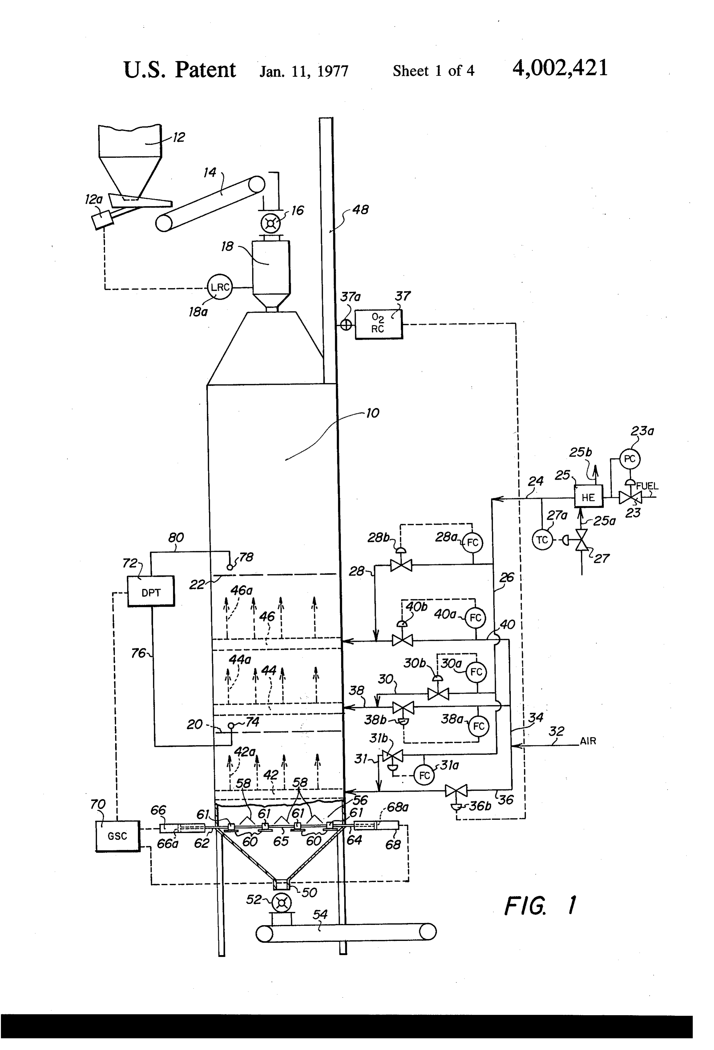
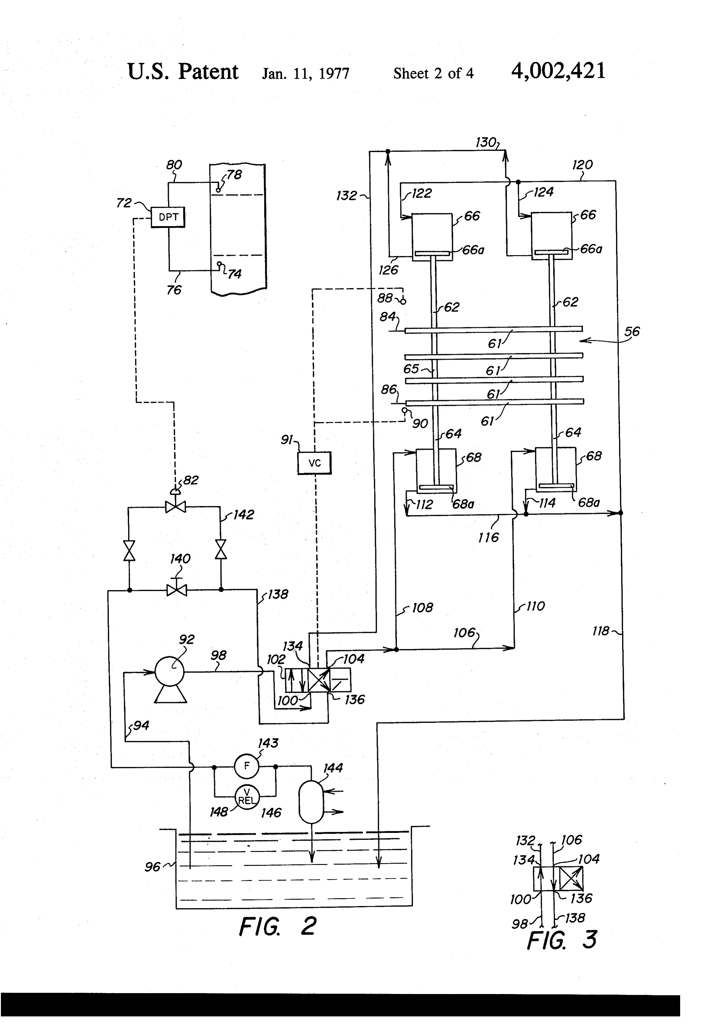
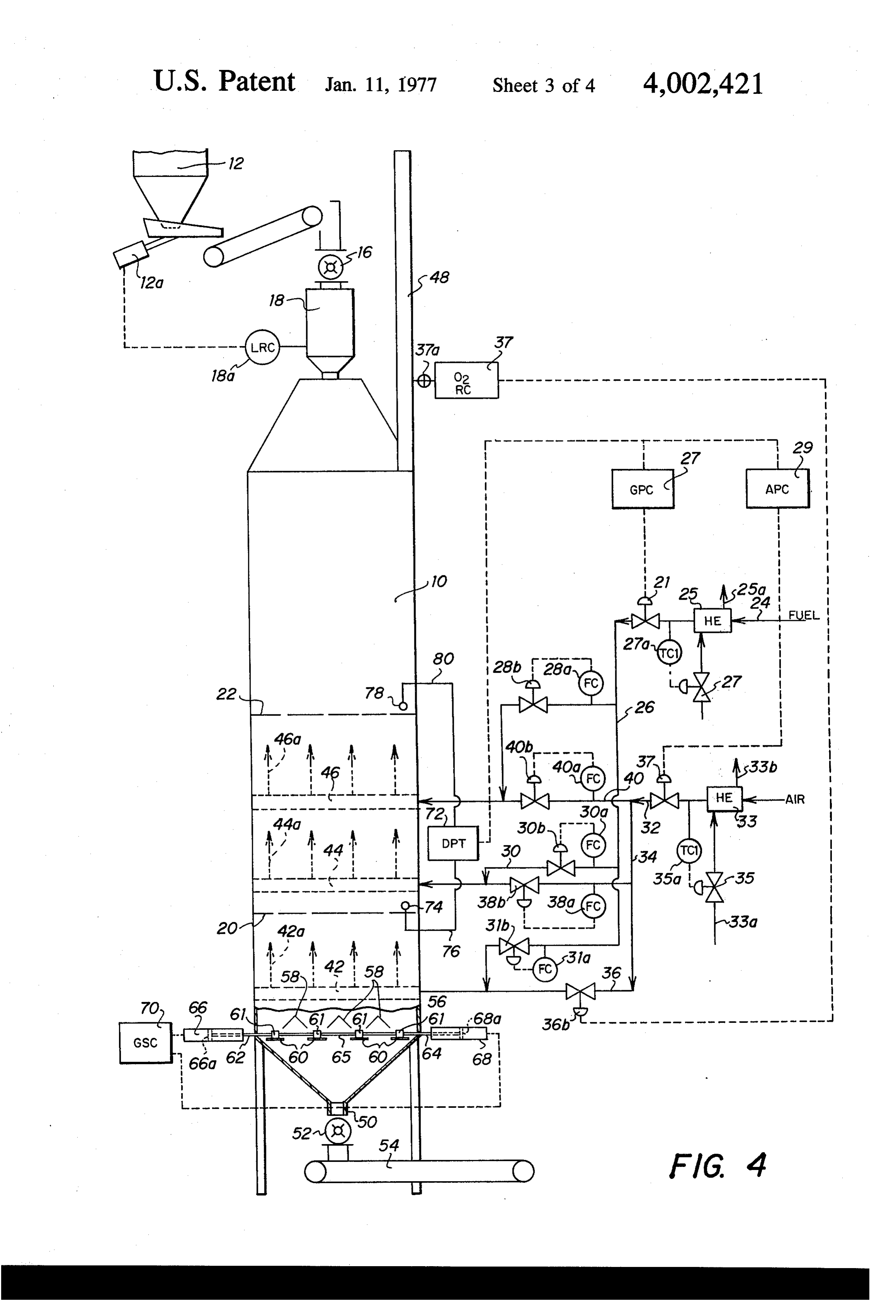
FIG. 3 is a partial view of FIG. 2 showing the four The combustion supporting gas which is delivered by way valve in its second position. these fluid distributor systems, will provide fuel for the FIG. 4 is a schematic illustration of a vertical kiln burning zone in the kiln, and allow proper heat treat ment of the particulate material passing downwardly equipped with control mechanisms in accordance with 60 therethrough a preferred embodiment of the subject invention; and by gravitational force. The off-gases from FIG. S is a schematic illustration of a vertical kiln the kiln are removed via stack 48. showing still another embodiment of the subject inven Oxygen controller 37 is connected to an oxygen sens tion. ing and transmitting leg 37a which operatively commu Now referring to the drawings, and in particular to 65 nicates with the interior of stack 48 to sense the quan FIG. 1, vertical kiln 10 comprises a conventional verti tity of oxygen within the effluent gas passing there cal kiln having an internal hollow shaft within which through and provide an input to oxygen controller 37. particulate material is subjected to heat treatment. The The input to oxygen controller 37 is compared to its set
Page 8
point to product an output for control valve 36b as of the difference of the two to control valve 82. It is illustrated in FIG. 1. Any suitable oxygen sensor and noted that the combination of pressure sensor 78 and transmitter and controller known in the art can be line 80 and the combination of pressure sensor 74 and utilized in the scope of this invention. Suitable such line 76 can each comprise a monometer tube. In this oxygen sensors, transmitters and controller which can instance, it is desirable to pass a uniform flow of purge be used in the scope of the subject invention comprises gas such as air through the monometer tubes. It is fur a 7,803 thermal magnetic oxygen analyzer positioned thermore noted that pressure sensing means 74 and 78 within stack 48 and attached to a 1991-30-0 133 milli can be positioned at any convenient spaced distance watt transmitter for furnishing inputs to a below and above, respectively, the burning zone in the 420-10-2-1205-10-1-1-100 controller. The output of 10 kiln. However, it is generally preferred that pressure the controller can pass through a 10970-2 electro sensor 74 be positioned adjacent the lower end of the pneumatic converter and then to pneumatic valve 366, burning zone and that sensor 78 be positioned adjacent for example. All of these control compartments are the upper end of the burning zone within kiln 10. available from Leeds and Northrup Co., Sunneytown Now again referring to FIG. 2, the pistons 66a within Pike, North Wales, Pa. 5 hydraulic cylinders 66 are coupled to rods 62, and rods The heat treated particulate material is passed from 62 carry pusher bars 61. Likewise, the pistons 68a outlet 50 through rotary seal 52 onto product conveyor within hydraulic cylinders 68 are operatively con 54. The flow of particulate material to outlet 50 is nected to rods 64, and rods 64 carry pusher bars 61. controlled by a grate control mechanism which oper Rods 62 and 64 are interconnected by rods 65. Switch ates in accordance with the subject invention. The 20 bars 84 and 86 depend from pusher bars 61 and func grate control mechanism will be described in detail tion, as shown, to actuate contacts 88 and 90, respec below. Grate 56 can be the linear grate for shaft kilns tively. contacts 88 and 90 actuate a conventional valve which is disclosed in U.S. Pat. No. 3,401,922 which control switch 91 which functions to alternately move patent is herein incorporated by reference into this four-way valve 102 between its first and second posi specification. However, any other suitable grate known 25 tions.
in the art can be used in the scope of this invention. The hydraulic system which is utilized to operate Grate 56 basically comprises a series of spaced diverter grate 56 includes a centrifugal pump 92 with an inlet plates 58, having retarder plates 60 positioned a spaced conduit 94 operatively communicating between hy distance below the opening between adjacent diverter draulic fluid reservoir 96 and the inlet of pump 92. plates 58. Generally, the distance of the edge of each 30 Conduit 98 communicates between the outlet of pump retarder plate 60 under each diverter plate 58 is deter 92 and port 100 of four-way valve 102. Four-way valve mined by the angle of repose of the material on itself, 102 can be any conventional four-way valve unit which passes through the kiln. Pusher bars 61 are recip known in the art. A suitable such four-way valve is a rocally mounted between diverter plates 58 and re Racine Model No. OD4-DNHS-102S. As shown in FIG. tarder plates 60. As illustrated in the embodiment 35 2, four-way valve 102 is in its first position, which will shown in the drawing, half of the pusher bars 61 are thereby allow port 100 to communicate with port 104. interconnected by rods 62 and the other half are inter Manifold conduit 106 operatively communicates with connected by rods 64. Rods 62 and 64 are connected port 104. Conduits 108 and 110 operatively communi by rods 65 and are controlled by the action of hydraulic cate between manifold conduit 106 and the front faces cylinders 66 and 68, respectively. More specifically, 40 of the pistons 68a within hydraulic cylinders 68. Con rods 62, 64 and 65 move pusher bars 61 in reciprocal duits 112 and 114 communicate between the rear faces motion by the action of hydraulic cylinders 66 and 68, of pistons 68a within hydraulic cylinders and conduit respectively. In essence, the controlled reciprocal 116. Conduit 116 operatively communicates with out movement of pusher bars 61 across retarder plates 60 let manifold conduit 118. Outlet manifold conduit 118 controls the flow of material passing to the outlet 50 45 communicates between hydraulic fluid reservoir 96 from openings between adjacent diverter plates 58. and conduit 120. Conduits 122 and 124 operatively The relative motion imparted to rods 62 and 64 by communicate between conduit 120 and the rear faces hydraulic cylinders 66 and 68, respectively, is regulated of pistons 66a within hydraulic cylinders 66. Conduits by grate speed controller 70. Grate speed controller 70 126 and 128 communicate between the front faces of in turn is operatively connected to differential pressure 50 pistons 66a within hydraulic cylinders 66 and conduit transmitter 72. Pressure sensor 74 is positioned adja 130. Conduit 132 communicates between valve port cent the lower end 20 of the burning zone within the 134 of four-way valve 102 and conduit 130. As shown, kiln and is operatively connected to differential pres with four-way valve 102 in its first position, valve port sure transmitter 72 via line 76. Pressure sensor 78 is 134 communicates with valve port 136 and valve port positioned at a point adjacent the upper end 22 of the 55 136 operatively communicates with conduit 138. Flow burning zone within the kiln 10 and is operatively con control valve 140 is positioned within conduit 138 and nected to differential pressure transmitter 72 via line conduit 142 comprises a by-pass loop communicating 80. with conduit 138 on either side of flow control valve A detailed view of a preferred control system used in 140. Flow control valve 140 can be any conventional the scope of the subject invention is schematically illus 60 such valve known in the art. A suitable such valve is a trated in FIG. 2. As shown, differential pressure trans constant volume, temperature and pressure compen mitter 72 can comprise any suitable type differential sated flow control valve such as a Racine Model F2 pressure transmitter known in the art having two signal AHS *-02* valve. Control valve 82 is positioned within inputs and one signal output. A suitable such device is conduit 142.
Honeywell Ap/P transmitter Model 292 12-01-0-1. 65 As previously set forth, control valve 82 is operated Thus, differential pressure transmitter 72 receives two by signals from differential pressure transmitter 72 and pressure inputs from pressure sensors 74 and 78, com can comprise any suitable control valve mechanism pares these inputs, and transmits a signal representative known in the art. For example, control valve 82 can
Page 9
comprise a Black, Sivalls, and Bryan Valve Operator to control the amount of hydraulic fluid passing type 70-13-10 and a Racine Model OF2-CHPW-50H through conduit 138 and thereby controls the speed of hydraulic valve. Conduit 138 communicates from con grate 56. When material enters the burning zone which duit 142 to hydraulic fluid reservoir 96. A filter 143 has either higher or lower porosity than the standard and a heat exchanger 144 are operatively positioned material of predetermined particle gradation (i.e., has a within conduit 138. In addition, by-pass conduit 146 is the higher or lower mass density) differential pressure of positioned around filter 143 with relief valve 148 posi fluid passing upwardly through the burning Zone tioned therein which will allow hydraulic fluid to by will accordingly be altered and the differential pressure pass the filter when a predetermined hydraulic pressure input to control valve 82 will adjust control valve 82 is reached, e.g., in case of pressure surges or in in 10 which in turn adjusts flow through conduit 138 and stances wherein the filter becomes clogged. alters the speed of gate 56. Thus, valve 82 is calibrated Now, referring to FIGS. 1-3, the operation of the to control the speed of grate 56 in response to varia control apparatus of the subject invention will be de tions of differential pressure outputs from differential scribed in detail. Basically, the control apparatus as set pressure transmitter 72. In essence, if material enters forth in the drawing functions to control the heat treat 15 the burning zone of the kiln which has a greater mass ment of particulate-materials passing through vertical density and thereby lower porosity than the predeter kiln 10 and assures a predetermined mass residence mined or average mass density, differential pressure time within vertical kiln 10. Generally, particulate ma transmitter 72 will indicate an increase in differential terial which is fed to the vertical kiln 10 will vary in pressure between the lower and upper portion of the particle size and in gradation of the particles and ac 20 burning zone. This will effect a closure of valve 82 and cordingly, will vary in mass density. a slowing down of grate 56 which will allow a longer Generally, particulate material such as previously burning time for the higher mass density material enter crushed and sized limestone delivered from storage bin ing the zone such that the material will have an equiva 12 into hopper 18 on kiln 10 will have a mass density lent mass residence time to that of the material with the which varies from a fixed minimum to a fixed maxi 25 predetermined mass density and thereby yield a sub mum. However, due to the fact that the particulate stantially uniform calcined product. Alternately, if the material is subjected to gravitation action not only material entering the burning Zone has a lower mass within storage bin 12, but also within the interior of density and therefore a greater porosity than the mate feeder hopper 18 and vertical kiln 10, the particle size rial of predetermined particle size, then the differential gradation will not be constant. Therefore, in accor 30 pressure between the upper and lower portions of the dance with a preferred embodiment of this invention, burning zone will be less than that which corresponds the grate speed of controller 70 is calibrated by passing to the material of predetermined particle size and the the crushed and sized particulate material, such as differential pressure transmitter will effect an opening limestone, through the kiln having a relative constant of control valve 82, and thereby allow grate 56 to oper heat input to the burning zone, and controlling the 35 ate at a faster rate so that the resulting mass residence grate speed until a product having the desired degree of time of the higher porosity lower mass density material calcination is obtained, e.g., a product wherein the isparticle equivalent to that of the material of predetermined size and again yield a substantially uniform carbon dioxide content of the calcined limestone falls within the range of from 2 weight percent of a control calcined product.
value, such as 3 or 3.5 wt. percent of the product. The 40 Referring to FIGS. 2 and 3, the operation of grate 56 calibration of the grate speed and differential pressure will be discussed in detail. Initially, valve 140 is ad is basically linear in nature, and it is found that to ob justed so that the flow of fluid therethrough in combi tain a product of the desired quality with the material nation with the flow of fluid through valve 82 will result having the nonuniform gradation that a substantially in a grate speed which is sufficient to yield a predeter uniform mass residence time will pass through the 45 mined mass residence time of particulate material of burning zone. Thus, the term "substantially uniform predetermined particle size passing through the burn mass residence time' is herein meant to include a mass ing zone of kiln 10. Now, with four-way valve 102 in its residence time which will yield a product having the first position as illustrated in FIG. 2, pump 92 is run at predetermined or controlled degree of calcination a constant speed and constantly withdraws hydraulic when passed through the burning zone (a degree of 50 fluid from reservoir 96 via conduit 94 and passes the calcination which falls within a desired range). hydraulic fluid to port 100 of four-way valve 102 via Generally, a relatively constant heat input is supplied conduit 98. The fluid passes through four-way valve to the burning zone in vertical kiln 10. This constant 102, port 104, and into conduit 106 and conduits 108 heat input is based upon an average or predetermined and 110, thereby passing fluid into the front portion of . particle gradation and consequently, an average or 55 hydraulic cylinders 68 and against the front faces of predetermined mass density of particulate material pistons 68a therewithin. This causes a retraction of which is passed through the heating zone to assure that pusher rods 64 and a movement of retarder plates 60. proper heat treatment of the particulate material is Since pusher rods 64 are interconnected to rods 62 by effected without resulting in either overburn or under rods 65, this also causes an extension of rods 62 and burn of the material as described above. The material 60 results in the front faces of piston 66a of hydraulic of the predetermined mass density will effect a prede cylinder 66 forcing fluid to conduit 130 via conduits termined pressure drop of fluid passing through the 126 and 128. Furthermore, the retraction of pistons burning zone, e.g., the air and fuel mixture and process 68a causes fluid to pass through conduits 112 and 114 gases released by calcination and gaseous combustion to outlet manifold conduit 118 and into conduits 120, products of the mixture which is passed upwardly 65 122, 124 and also into reservoir 96. Fluid from conduit through kiln 10 from fluid distributor systems 42, 44 130 passes to conduit 132 into valve port 134 through and 46. Thus, valve 140 is set at a predetermined open four-way valve 102 to valve port 136 and into conduit ing and functions in combination with control valve 82 138.
Page 10
The fluid passes through conduit 138, through con deleteriously affect the process is eliminated from the duit 142, control valve 82, valve 140, through filter burning zone. More specifically, referring to FIG. 1, the 143, heat exchanger 144, wherein the fluid is cooled oxygen sensing and transmitting leg 37a is positioned and back to reservoir 96. This action continues until within stack 48 and determines the quantity of oxygen switch bar 86 touches contact 90. When contact 90 is within the effluent gases passing from the burning Zone actuated, valve control switch 91 moves four-way valve within kiln 10. A signal indicating the sensed oxygen 102 to its second position as illustrated by the partial content within the effluent gases is transmitted via view in FIG. 3. In this instance, the pump output flow oxygen sensing and transmitting leg 37a to oxygen ing through conduit 98 to valve port 100 passes directly controller 37 wherein it is compared with a set point to valve port 134 into conduits 132, 130 and 126 and O which corresponds to the desired content or oxygen 128 to the front face of pistons 66a and hydraulic cylin within the effluent stream. Oxygen controller 37 then ders 66. This action causes pistons 66a to retract, and generates a signal which is transmitted to valve 36b to rods 62, pusher bars 61 and rods 64 to be moved control the relative amount of air passing into the burn toward hydraulic cylinders 66. This action causes fluid ing zone of kiln 10. Thus, when the oxygen sensing and against the rear face of piston 66a to pass through 5 transmitting leg 37a indicates that too much oxygen is conduits 122, 124 and to conduits 120, and 18, 114, present within the effluent gases, the signal passed to 112 to the rear faces of pistons 68a of hydraulic cylin valve 36b results in a proportional closing of valve 36b. ders 68. This in turn will force fluid which is in contact This occurs until the desired level of oxygen is main with the front faces of pistons 68a of hydraulic cylin tained within the effluent gases passing through stack ders 68 into conduits 108, 110, 106, into valve port 104 20 48. Alternately, when the oxygen analyzer indicates of four-way valve 102. that a desired minimum quantity of oxygen is not con The fluid passes through four-way valve 102 to valve tained within the effluent gas passing through stack 48, port 136 into conduit 138 and again through conduit the signal passing from oxygen controller 37 will result 142, control valve 82, filter 143, heat exchanger 144, in an opening of valve 36b until the desired oxygen back to the reservoir 96. This action continues until 25 content is maintained within the effluent gases passing switch bar 84 actuates contact 88 which in turn actu through stack 48. The desired level of oxygen within ates valve control switch 91 which moves four-way the effluent gases will vary in accordance with the pro valve 102 again to its first position, at which time the cess. In most processes, it is generally desirable to sequence is repeated. As can be seen, changes from the maintain between 1 and 2% oxygen in the effluent gas differential pressure transmitter 72 alter the opening of 30 to assure efficient utilization of the fuel and yet prevent valve 82, and thereby controls the speed of grate mech an excess quantity of oxygen within the burning Zone anism 56. More specifically, when four-way valve 102 which can yield deleterious results.
is in its first position and fluid from centrifugal pump 92 It is also noted that in accordance with this embodi is being pumped against the front faces of pistons 68a ment, it is desirable to pre-heat the fuel stream which within hydraulic cylinders 68 and thereby causing them 35 passes to manifold 26 in a manner as shown in FIG. 1. to retract within the hydraulic cylinders 68, rods 62 are As explained above, the fuel passes to manifold 26 at a extending from hydraulic cylinders 66 and thereby, the constant pressure by the action of valve 23 and pres front faces of pistons 66a within hydraulic cylinders 66 sure controller 23a. Furthermore, the heat exchanger are forcing fluid through the outlet flow path toward 25 by the cooperation of valve 27 and temperature reservoir 96 which includes a passage through valves 40 controller 27a will assure that the fuel is preheated to a 140 and control valve 82. Thus, the back pressure constant temperature. In this manner, a known volume imparted on the system by an opening or closing of of fuel metered into manifold 26 will always contain a control valve 82 will affect the speed at which the fluid known molar quantity of combustible material. There from the centrifugal pump 92 will move pistons 68a fore, the relative control of the air to this known quan and 66a. 45 tity of gas assures that with varying atmospheric condi It has been found that the above-described operation tions, a known heat input will be passed to the interior of a vertical heat treating vessel such as a vertical kiln of the kiln. It is also noted that it is within the scope of functions efficiently under ideal conditions. However, this invention to connect oxygen controller 37 to valves it has been found in actual operation that the supply of which control both the flow of the fuel stream and air a constant heat input to the interior of the burning zone 50 stream or to valves which control only the fuel stream is quite difficult. Two conditions exist which contribute or the air stream. However, it is generally preferable to to these difficulties. The first is variable degrees of air operate valve 36b in a manner schematically illustrated loss through rotary seal 52 and the second is the inabil in FIG. 1 and discussed above.
ity of the volumetric air and gas controls to maintain a It is noted that the above embodiments disclosed in constant gravimetric flow of natural gas and air with 55 FIGS. 1-3 maintain a uniform heat treatment of partic varying atmospheric conditions. It is necessary in the ulate material passing through the heating zone in a heat treatment of particulate materials such as lime kiln by varying the rate at which the particulate mate stone, or oil shale that a predetermined well regulated rial passes through the burning zone in relation to the heat input be maintained within the burning zone and specific gravity of the mass passing to the burning zone, that excess air be closely controlled. In essence, the 60 and also by maintaining a uniform oxygen content maximum quantity of free or unconverted oxygen in within the burning zone. It is also within the scope of the burning zone should be controlled to very close the subject invention to vary the heat input to the burn tolerances. Therefore, in accordance with a preferred ing zone of a vertical kiln in response to changes in the embodiment of the subject invention, an apparatus and specific gravity of the mass of material flowing through process is provided which will assure a uniform heat 65 the burning zone. Specific embodiments of this aspect treatment of particulate material in a heat treating zone are illustrated in FIGS. 4 and 5. wherein the heat input is maintained within desired Now referring to FIG. 4, a control mechanism for limits and excess oxygen beyond the limit that would kiln 10 is schematically illustrated in accordance with a
Page 11
preferred embodiment of the subject invention wise, air is passed through heat exchanger 33, control whereby the heat input to a heat treating zone in kiln valve 32 and into air manifold 34. The relative quantity 10 is controlled in response to differential pressure of fuel-air is set to maintain a predetermined heat input fluctuations of the combustion-supporting fluid and based upon the average or predetermined mass density process gases flowing upwardly through the heat treat of particulate material which passes through kiln 10. ing zone in the kiln. In FIG. 4, many of the components However, when material enters the burning Zone are the same as that illustrated in FIGS. 1-3 and the which has either a higher or lower porosity than the same components are designated by the same charac standard material or predetermined particle gradation ters as shown in FIGS. 1-3. The basic changes in the (i.e., has a higher or lower mass density), the differen controls are set forth below. 10 tial pressure of the fluid passing upwardly through the Level controller 18a is operatively connected to dis burning zone which is measured by differential pres charge control mechanism 12a. Differential pressure sure transmitter 72 is accordingly altered and a differ control legs 76 and 80 are positioned below and above ential pressure input to gas pressure controller 27 and the burning zone, respectively, within kiln 10 in a man air pressure controller 29 will result in outputs from gas ner as described in relation to FIG. I. However, the 5 pressure controller 27 and air pressure controller 29 output of differential pressure transmitter is operatively proportionally altering the quantity of gas and air connected to gas pressure controller 27 and air pres which passes through valves 21 and 37, respectively. sure controller 29 as shown schematically in FIG. 4. Thus, each input from differential pressure transmitter Grate speed controller 70 is set to operate at a constant 72 is compared with set points within controllers 27 speed which is equivalent to uniformly withdraw partic and 29, respectively, to effect an alteration of the out ulate materials having an average or predetermined puts of the controllers 27 and 29 to the valves 21 and mass density. Gas pressure controller 27 and air pres 37 and either decrease or increase the heat input pass sure controller 29 can be any conventional valve con ing into the burning zone. More specifically, if material trollers known in the art. The output of gas pressure enters the burning zone of the kiln which has a greater controller 27 is operatively connected to pressure con 25 mass density and thereby a lower porosity than the trol valve 21 which in turn is operatively positioned predetermined or average mass density, differential within fuel conduit 24. Likewise, the output of air pres pressure transmitter 72 will indicate an increase in sure controller 29 is operatively connected to pressure differential pressure between lower and upper portion control valve 37 which is operatively positioned within of the burning zone. This signal is transmitted to gas air supply conduit 32. Furthermore, heat exchanger 33 30 pressure controller 27 and air pressure controller 29 is operatively connected to air supply conduit 32. A and will effect a proportional opening of valves 21 and heat exchange fluid such as steam or waste heat stream 37, respectively, to thereby increase the heat input of such as a kiln waste heat stream is passed to the heat the combustion supporting stream passing from fluid exchange fluid inlet of heat exchanger 33 via conduit distributors 42, 44 and 46. Since grate 56 is withdraw 33a, passed in indirect contact with the air flowing 35 ing particulate material from the lower portion of the through conduit 32 and then removed from heat ex kiln at a relatively constant volumetric rate, the in changer 33 via outlet conduit 33b. The quantity of heat crease in heat content of the heating fluid passed to the exchange fluid which passes through conduit 33a is interior of kiln 10 results in the particulate material controlled by valve 35 which in turn is controlled by passing through the heating zone having an equivalent temperature controller 35a which senses the tempera 40 heat treatment to that of the material with a predeter ture within conduit 32. Alternately, steam can be mined mass density. This results in a substantially uni passed directly into the air stream passing through form heat treated product. Alternately, if the material conduit 32 to provide not only heat but a controlled entering the burning zone has a lower mass density and amount of moisture therein. therefore a greater porosity than the material of prede In operation of the embodiment set forth in FIG. 4, 45 termined particle size, then the differential pressure particulate material such as previously crushed and between the upper and lower portions of the burning sized limestone is delivered from storage bin 12 into zone will be less than that which corresponds to the hopper 18 at a generally uniform rate based on the material of predetermined particle size and the differ weight of the limestone. However, this material will ential pressure transmitter 72 will transmit signals to have a mass density which varies from a fixed minimum 50 gas pressure controller 27 and air pressure controller to a fixed maximum. Furthermore, due to the fact that 29 which when compared to the set points in these the particulate material is subjected to gravitation ac controllers results in outputs from these controllers to tion not only within storage bin 12 but also within the valves 21 and 37, respectively, which will effect a pro interior of feeder hopper 18 in vertical kiln 10, the portionate closing of the valves so that a proportionally . particulate size gradation will not be constant. Initially, 55 lower heat input will be contained within the fluid pass a relatively constant heat input is supplied to the burn ing from fluid distributors 42, 44 and 46. The material ing zone in vertical kiln 10 based upon an "average' or passing through the burning zone will have equivalent predetermined particle gradation and consequently an heat treatment to that of the material of predetermined average or predetermined mass density of particulate particle size.
material which is passed through the heating Zone. 60 Furthermore, during the above operation, oxygen Grate speed controller 70 controls the speed of grate sensing probe 37a is constantly sensing the oxygen 56 at a constant speed sufficient to withdraw a rela content within the effluent gases passing through stack tively constant volumetric amount of the particulate 48 and passing a signal to oxygen controller 37. The material having the average or predetermined mass output of oxygen controller 37 which is the result of the density which is fed to kiln 10. The fuel passes through 65 compared sensed oxygen input and the set point of the conduit 24 into fuel manifold 26 and is preheated to a controller will effect either an opening or a closing of constant temperature in heat exchanger 25 and main valve 36b positioned within air line 36 to assure that tained at a predetermined pressure by valve 21. Like effluent gases passing through stack 48 will have a
Page 12
predetermined oxygen content and furthermore to Table I-continued assure that excess oxygen will not be contained within STONE GRADATION the fluid passing to the burning zone in the kiln. % Retained on Screed Now referring to FIG. 5, a variation of the embodi Day Time 1-2' 34' A.'' O ment set forth in FIG. 4 is schematically illustrated. 5 Deviation 6.6 0.3 9.8 8.6 4.2 Basically, all components in the embodiment shown in
FIG. 5 are the same except that the output from oxygen controller 37 forms an input to air pressure controller As can be seen, the gradation of the limestone deliv 29 and the valve 36b is controlled by a flow controller ered from bin 12 varied tremendously with time, even 36a. The operation of the embodiment set forth in FIG. 10 though the mass density only ranged from 76 to 86 5 is the same as that set forth in FIG. 4 except that the output from oxygen controller 37 controls the set point pounds per cubic foot.
Control valve 82 was calibrated such that the grate to air pressure controller 29 such that the output from speed of grate 56 varied in response to a change in the air pressure controller 29 inherently contains an adjust density of the limestone passing through the burning ment to assure that a constant oxygen content is main 15 zone between differential pressure sensors 74 and 78 as tained within the effluent gases which pass the step 48. determined by changes in the differential pressure of It is noted that the embodiments as illustrated in
FIGS. 4 and 5 can be utilized in various types of heat lated fluid passing therethrough. The grate speed was corre treating vessels to control one or more heat treating this range with each differential pressure increment within zones. For example, in the retorting of oil shale it is 20 + 1 wt.% toofyield a product which contained about 1.5 desirable to pass the oil shale downwardly through the stantially uniform massdioxide carbon and thereby yield a sub vertical shaft and expose it to at least two heat treating zone. It was specifically found thatthrough flow rate the burning temperatures. The control mechanisms schematically range of from about 76 to about 86 pounds perdensity for a mass cubic illustrated in FIGS. 4 and 5 can be utilized to control the heat input to such heat treatment zones. 25 foot, a corresponding differential pressure range of The following examples are given to better facilitate about 7 inches of water would result. This differential the understanding of this invention and are not in pressure range was used to control the valve 82. In essence the average grate speed setting corresponded tended to limit the scope thereof: to a differential pressure of the fluid passing through Example 1 30 the burning zone which would indicate that the mass An apparatus such as illustrated in FIGS. 1-3 was density of the material therein was about 81 pounds per cubic foot, the fastest grate speed setting corresponded utilized to calcine limestone. The crushed and sized limestone which was calcined generally had a particle to a differential pressure which indicated the material size ranging from about % to about 2% inches. The had and a mass density of about 76 pounds per cubic foot;
the slowest grate speed setting corresponded to a gradation of the limestone varied substantially but it differential
pressure which indicated that the mass generally had a mass density in the range of from about density of the material passing through the burning 76 to about 86 pounds per cubic foot. Due to the ten dency of the smaller particles to gravitate downwardly zone was about 86 pounds per cubic foot. Kiln 10 was initially set to operate with natural gas within storage bin 12 and kiln 10, the gradation of the entering limestone passing through the burning Zone of kiln 10 40 conduit 24 and air entering conduit 32 to will vary considerably with time. As an example, lime establish a burning zone within the kiln of between stone which had a mass density ranging from about 76 1500 and 2800 F, generally, between broken lines to about 86 pounds per cubic foot and which was deliv showing the lower end 20 and the upper end 22 ered from storage bin 12 over a period of 8 days was thereof. This is accomplished by delivering air to con measured for particle size distribution two or three 45 duit 32 and natural gas to conduit 24. The gas in con times a day and the results are shown in Table I below. duit 24 was maintained at pressure of 29 psig by valve 23 and pressure controller 23a, and a temperature of
Table about 80° F by heat exchanger 25. Furthermore, the fluid passing into the kiln comprised about 7,100 stan
STONE GRADATION 50 dard cubic feet per minute of air through fluid distribu % Retained on Screed
Day Time 1-A.'' 94''. A.'' O tor 42 (flow controller 31b was set to close valve 31a
and allow no gas to pass through conduit 31); a total of 1700 19.7 330 25.0 2O2 2. about 1,305 standard cubic feet per minute of a rich
gas-air mixture which consisted of a ratio of about 4.9 3 000 8.6 6.7 18. 1.6 O 55 standard cubic feet per minute of air to about 3 stan 0900 47.5 32.5 10.0 4.5 5.5 dard cubic feet of natural gas delivered through fuel
distritutor system 44; and about 2,755 standard cubic
O900 52.3 20.4 20.4 3.9 3.0 feet per minute of lean fuel-air mixture was passed
through fluid distributor system 46 and consisted of a 0900 27.2 30.5 23.4 18.5 0.4 60 ratio of about 5.8 standard cubic feet of air to about 1 700 37.8 50. 9.1 5 15 standard cubic foot of fuel. This resulted in excess air
0900 24.0 55.0 2O. 0.9 O within the kiln of about 8.74 weight percent which in 1700 1.7 44.0 40.9 12.9 0.5 turn results in oxygen content of about 1.8 volume
percent. Therefore, the set point of oxygen controller 700 35.1 29. 16.3 16.3 3.2 65 37 was set to correspond to an oxygen content of about
1.8 volume percent in the effluent gases passing 1700 56.0 35.0 7.5 0.9 0.6 through stack 48. Thus, the output of oxygen controller Ave. 3.3 36.0 9.6 10.1 3.0 27, controlled air valve 36d to provide an air flow
Page 13
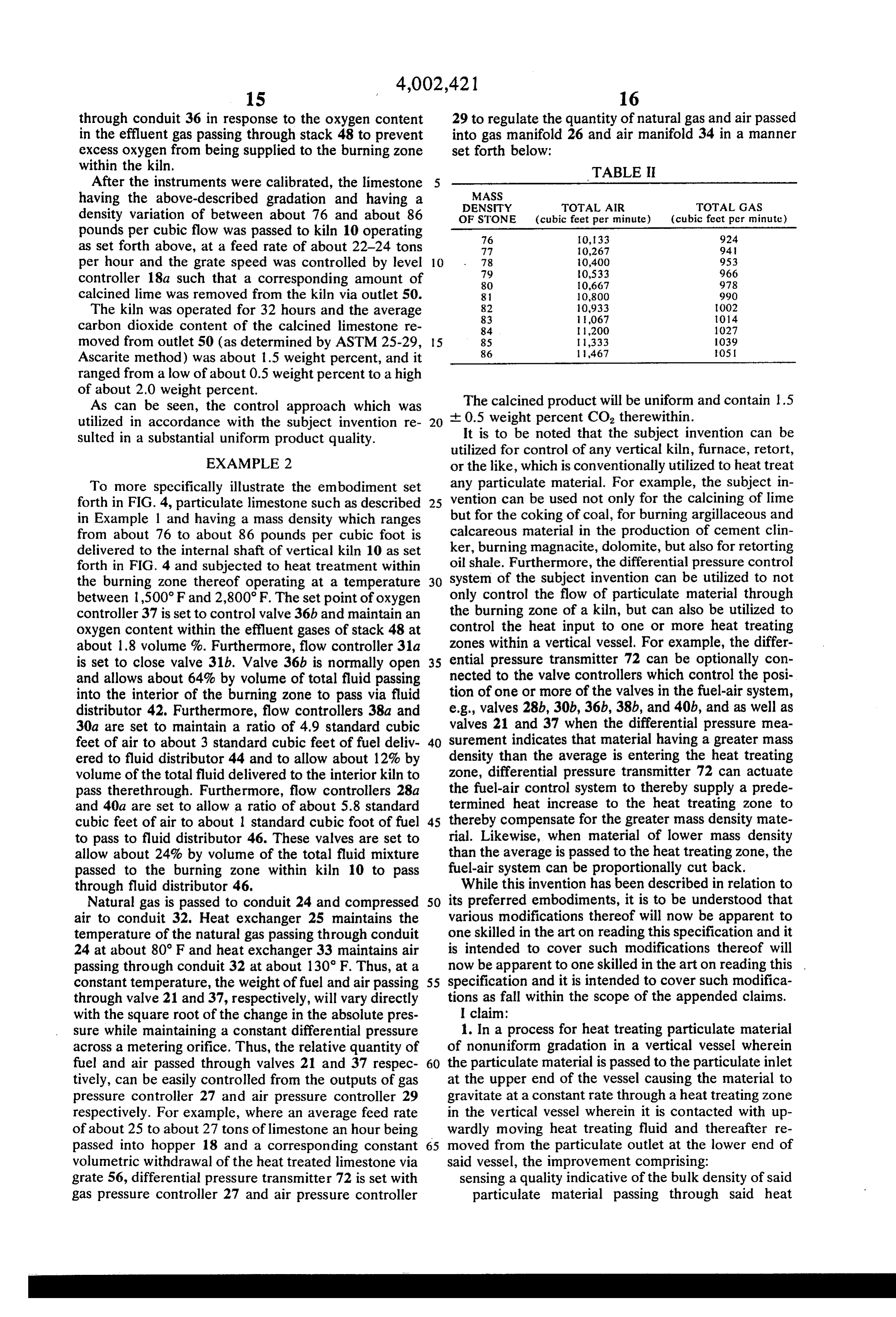
through conduit 36 in response to the oxygen content 29 to regulate the quantity of natural gas and air passed in the effluent gas passing through stack 48 to prevent into gas manifold 26 and air manifold 34 in a manner excess oxygen from being supplied to the burning zone set forth below:
within the kiln.
After the instruments were calibrated, the limestone TABLE II having the above-described gradation and having a MASS
density variation of between about 76 and about 86 OF STONE (cubic feet per minute) (cubic feet per minute) pounds per cubic flow was passed to kiln 10 operating 76 10,133 924 as set forth above, at a feed rate of about 22-24 tons 77 10,267 94. per hour and the grate speed was controlled by level 10 78
controller 18a such that a corresponding amount of 80 10,667 978 calcined lime was removed from the kiln via outlet 50. 8. 10,800 990 The kiln was operated for 32 hours and the average 82
carbon dioxide content of the calcined limestone re 84 1,200 1027 moved from outlet 50 (as determined by ASTM 25-29, 5 85
Ascarite method) was about 1.5 weight percent, and it ranged from a low of about 0.5 weight percent to a high of about 2.0 weight percent.
As can be seen, the control approach which was The calcined product will be uniform and contain 1.5 utilized in accordance with the subject invention re 20 -- 0.5 weight percent CO, therewithin. sulted in a substantial uniform product quality. It is to be noted that the subject invention can be utilized for control of any vertical kiln, furnace, retort,
EXAMPLE 2 or the like, which is conventionally utilized to heat treat To more specifically illustrate the embodiment set any particulate material. For example, the subject in forth in FIG. 4, particulate limestone such as described 25 vention can be used not only for the calcining of lime in Example 1 and having a mass density which ranges but for the coking of coal, for burning argillaceous and from about 76 to about 86 pounds per cubic foot is calcareous material in the production of cement clin delivered to the internal shaft of vertical kiln 10 as set ker, burning magnacite, dolomite, but also for retorting forth in FIG. 4 and subjected to heat treatment within oil shale. Furthermore, the differential pressure control the burning zone thereof operating at a temperature 30 system of the subject invention can be utilized to not between 1,500°F and 2,800°F. The set point of oxygen only control the flow of particulate material through controller 37 is set to control valve 36b and maintain anthe burning zone of a kiln, but can also be utilized to oxygen content within the effluent gases of stack 48 at control the heat input to one or more heat treating about 1.8 volume %. Furthermore, flow controller 31a zones within a vertical vessel. For example, the differ is set to close valve 31b. Valve 36b is normally open 35 ential pressure transmitter 72 can be optionally con and allows about 64% by volume of total fluid passing nected to the valve controllers which control the posi into the interior of the burning zone to pass via fluid tion of one or more of the valves in the fuel-air system, distributor 42. Furthermore, flow controllers 38a and e.g., valves 28b, 30b, 36b, 38b, and 40b, and as well as 30a are set to maintain a ratio of 4.9 standard cubic valves 21 and 37 when the differential pressure mea feet of air to about 3 standard cubic feet of fuel deliv 40 surement indicates that material having a greater mass ered to fluid distributor 44 and to allow about 12% by density than the average is entering the heat treating volume of the total fluid delivered to the interior kiln to zone, differential pressure transmitter 72 can actuate pass therethrough. Furthermore, flow controllers 28a the fuel-air control system to thereby supply a prede and 4.0a are set to allow a ratio of about 5.8 standard termined heat increase to the heat treating zone to cubic feet of air to about 1 standard cubic foot of fuel 45 thereby compensate for the greater mass density mate to pass to fluid distributor 46. These valves are set to rial. Likewise, when material of lower mass density allow about 24% by volume of the total fluid mixture than the average is passed to the heat treating zone, the passed to the burning zone within kiln 10 to pass fuel-air system can be proportionally cut back. through fluid distributor 46. While this invention has been described in relation to Natural gas is passed to conduit 24 and compressed 50 its preferred embodiments, it is to be understood that air to conduit 32. Heat exchanger 25 maintains the various modifications thereof will now be apparent to temperature of the natural gas passing through conduit one skilled in the art on reading this specification and it 24 at about 80 F and heat exchanger 33 maintains air is intended to cover such modifications thereof will passing through conduit 32 at about 130 F. Thus, at a now be apparent to one skilled in the art on reading this constant temperature, the weight of fuel and air passing 55 specification and it is intended to cover such modifica through valve 21 and 37, respectively, will vary directly tions as fall within the scope of the appended claims. with the square root of the change in the absolute pres I claim:
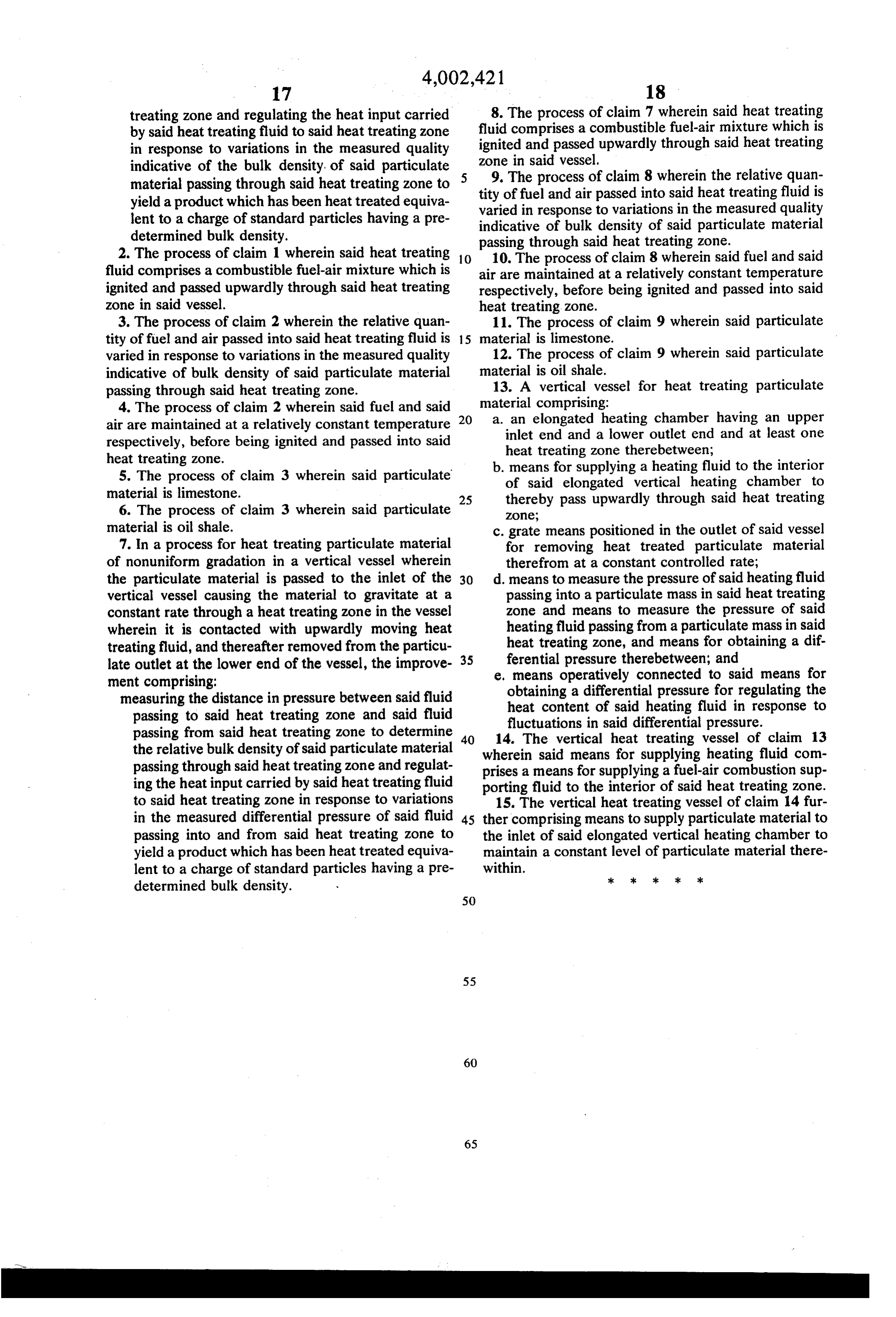
sure while maintaining a constant differential pressure 1. In a process for heat treating particulate material across a metering orifice. Thus, the relative quantity of of nonuniform gradation in a vertical vessel wherein fuel and air passed through valves 21 and 37 respec 60 the particulate material is passed to the particulate inlet tively, can be easily controlled from the outputs of gas at the upper end of the vessel causing the material to pressure controller 27 and air pressure controller 29 gravitate at a constant rate through a heat treating zone respectively. For example, where an average feed rate in the vertical vessel wherein it is contacted with up of about 25 to about 27 tons of limestone an hour being wardly moving heat treating fluid and thereafter re passed into hopper 18 and a corresponding constant 65 moved from the particulate outlet at the lower end of volumetric withdrawal of the heat treated limestone via said vessel, the improvement comprising: grate 56, differential pressure transmitter 72 is set with sensing a quality indicative of the bulk density of said gas pressure controller 27 and air pressure controller particulate material passing through said heat
Page 14
treating zone and regulating the heat input carried 8. The process of claim 7 wherein said heat treating by said heat treating fluid to said heat treating zone fluid comprises a combustible fuel-air mixture which is in response to variations in the measured quality zone ignited and passed upwardly through said heat treating indicative of the bulk density, of said particulate in said vessel.
material passing through said heat treating zone to tity of fuelprocess 9. The and of claim 8 wherein the relative quan air passed into said heat treating fluid is yield a product which has been heat treated equiva varied in response to variations in the measured quality lent to a charge of standard particles having a pre indicative of bulk density of said particulate material determined bulk density. passing through said heat treating Zone. 2. The process of claim 1 wherein said heat treating O 10. The process of claim 8 wherein said fuel and said fluid comprises a combustible fuel-air mixture which is air are maintained at a relatively constant temperature ignited and passed upwardly through said heat treating respectively, before being ignited and passed into said zone in said vessel. heat treating zone.
3. The process of claim 2 wherein the relative quan 11. The process of claim 9 wherein said particulate tity of fuel and air passed into said heat treating fluid is 15 material is limestone.
varied in response to variations in the measured quality 12. The process of claim 9 wherein said particulate indicative of bulk density of said particulate material material is oil shale.
passing through said heat treating zone. 13. A vertical vessel for heat treating particulate 4. The process of claim 2 wherein said fuel and said material comprising:
air are maintained at a relatively constant temperature 20 a. inlet an elongated heating chamber having an upper end and a lower outlet end and at least one respectively, before being ignited and passed into said heat treating zone therebetween; heat treating zone. b. means for supplying a heating fluid to the interior 5. The process of claim 3 wherein said particulate of said elongated vertical heating chamber to material is limestone. 25 thereby pass upwardly through said heat treating 6. The process of claim 3 wherein said particulate ZOne;
material is oil shale. c. grate means positioned in the outlet of said vessel 7. In a process for heat treating particulate material for removing heat treated particulate material of nonuniform gradation in a vertical vessel wherein therefrom at a constant controlled rate; the particulate material is passed to the inlet of the 30 d. means to measure the pressure of said heating fluid vertical vessel causing the material to gravitate at a passing into a particulate mass in said heat treating constant rate through a heat treating zone in the vessel zone and means to measure the pressure of said wherein it is contacted with upwardly moving heat heating fluid passing from a particulate mass in said treating fluid, and thereafter removed from the particu heat treating zone, and means for obtaining a dif late outlet at the lower end of the vessel, the improve 35 ferential pressure therebetween; and ment comprising: e, means operatively connected to said means for measuring the distance in pressure between said fluid obtaining a differential pressure for regulating the passing to said heat treating zone and said fluid heat content of said heating fluid in response to fluctuations passing from said heat treating zone to determine 40 14. The vertical in said differential pressure. the relative bulk density of said particulate material wherein said means heat for treating vessel of claim 13 supplying heating fluid com passing through said heat treating Zone and regulat prises a means for supplying a fuel-air combustion sup ing the heat input carried by said heat treating fluid porting fluid to the interior of said heat treating zone. to said heat treating zone in response to variations 15. The vertical heat treating vessel of claim 14 fur in the measured differential pressure of said fluid 45 ther comprising means to supply particulate material to passing into and from said heat treating zone to the inlet of said elongated vertical heating chamber to yield a product which has been heat treated equiva maintain a constant level of particulate material there lent to a charge of standard particles having a pre within. ck >k 3k ck ck determined bulk density.
Page 15
UNITED STATES PATENT OFFICE
CERTIFICATE OF CORRECTION
Patent No. 4,002,421 Dated January 11, 1977 James R. Summer
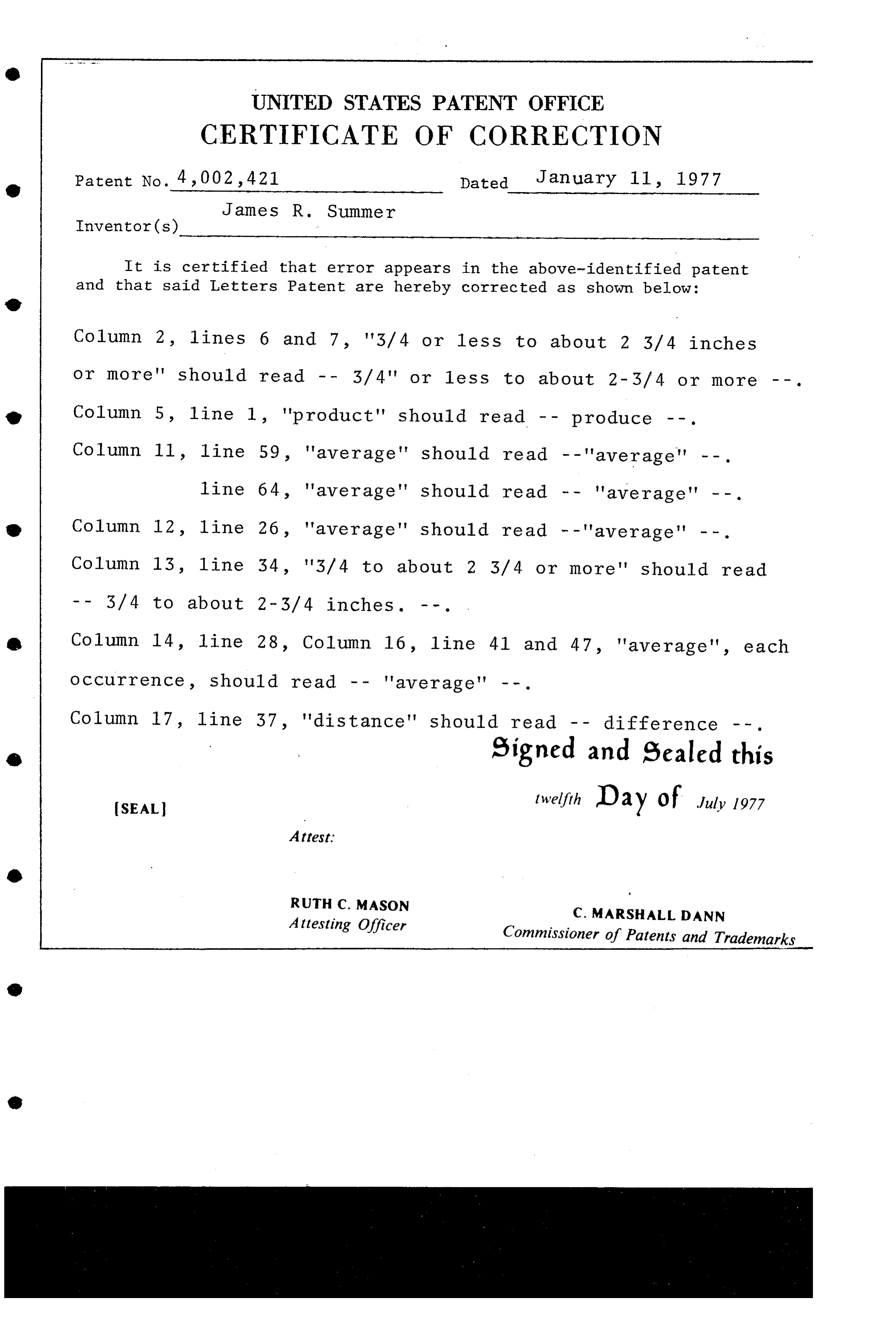
It is certified that error appears in the above-identified patent and that said Letters Patent are hereby corrected as shown below:
Column 2, lines 6 and 7, '3/4 or 1ess to about 2 3/4 inches or more' should read -- 3/4" or 1ess to about 2-3/4 or more --. Column 5, line 1, "product" should read -- produce --. Column 11, line 59, 'average' should read --'average" --. line 64, 'average" should read -- 'average" --.
Column 12, line 26, 'average' should read -- 'average' --. Column 13, 1ine 54, '3/4 to about 2 3/4 or more' should read
Column 14, line 28, Column 16, line 41 and 47, "average", each Occurrence, should read -- 'average' --.
Column 17, line 57, 'distance' should read -- difference --. Signed and Sealed this
SEAL twelfth Day of July 1977 Attest:
RUTH C. MASON
Attesting Officer C. MARSHALL D ANN
Commissioner of Patents and Trademarks
Provenance
- Collection
- Cited prior art
- Original PDF
- patentimages.storage.googleapis.com →
- Filed
- 1975-03-07
- Pages
- 15
- Method
- pdftotext (the PDF's own text layer) + pdftoppm 300dpi page scans
- Source
- Google Patents bibliographic record
- Granted
- 1977-01-11
- Inventors
- James R. Summer; ROUND ROCK LIME Co
- Transcribed from
- patentimages.storage.googleapis.com →