patent · US5486107
Determination of fuel characteristics
23 January 1996
Page 1 — bibliographic record
United States Patent (19) 11 Patent Number: 5,486,107 Bonne (45) Date of Patent: Jan. 23, 1996 54 DETERMINATION OF FUEL 4,993,222 2/1991 Iwai et al. ............................. 431f12 X CHARACTERISTICS 5,177,696 l/1993 Bonne ..................................... 364/557 5,187,674 2/1993 Bonne ..................................... 364/558 75 Inventor: Ulrich Bonne, Hopkins, Minn. 5,220,830 6/1993 Bonne ......... ... 73,204.21 5,235,844 8/1993 Bonne et al. .......................... 73/2401 5,303,167 4/1994 Bonne ..................................... 364,556 73) Assignee: Honeywell, Inc., Minneapolis, Mich. 5,311,447 5/1994 Bonne ..................................... 364/509 21 Appl. No.: 301,225 FOREIGN PATENT DOCUMENTS 22 Filed: Sep. 6, 1994 0348244 12/1989 European Pat. Off..
Related U.S. Application Data 9106809 5/1991 WIPO
Primary Examiner-Carl D. Price 63 Continuation of Ser. No. 828,135, Jan. 30, 1992, abandoned. Attorney, Agent, or Firm-John G. Shudy, Jr.
52) U.S. Cl. ................................... 431/12: 431/2; 431/89; 57 ABSTRACT t 431/90.3657,373 Amethod of determining thermophysical orthermochemical 58) Field of Search .............................. 73/25,03, 204.11; parameters of a fuel gas is disclosed which has wide 364/557, 556; 374/43; 431/2, 13, 12, 18, application both as to applicable fuels and applicable param 89, 90 eters. A relationship has been discovered that allows the
determination of many parameters based on a basic rela tionship with the characteristic specific heat and thermal
rate of change of these characteristics at the reference 4,359,284 11/1982 Kude et al.. conditions.
4,961,348 10/1990 Bonne. 26 Claims, 6 Drawing Sheets
FUEL
A VVE 24
28 COMBUSTION
CHAMBER
COMBUSTON
CONTROLLER
CONTROL INPUTS
Page 2
Drawing sheet — no readable text.
Page 3
Drawing sheet — no readable text.
Page 4
- HH, ACTUAL H.HTGVALIN MJ/m (15°C)
COMPARISON BETWEEN ACTUAL AND COMPUTED
FG 3 HEATING VALUE OF GASES
- HH, ACTUAL H.HTGVALIN MJ/m (15°C)
COMPARISON BETWEEN ACTUAL AND COMPUTED
HEATING VALUE OF GASES
Page 5
Drawing sheet — no readable text.
Page 6
Drawing sheet — no readable text.
Page 7
Drawing sheet — no readable text.
Page 8
DETERMINATION OF FUEL interest. The use of such devices to accurately determine CHARACTERISTICS thermal conductivity, k, and specific heat are shown in Aagard, et al., above, and Bonne, et al. 793, also cited
This application is a continuation of application Ser. No. above, also enables the accurate determination of specific 07/828,135, filed Jan. 30, 1992, abandoned. 5 gravity of a species of interest. The related application, Ser. No. 07,789,411 filed Nov. 1,
BACKGROUND OF THE INVENTION 1991, discloses the use of k and c for a determination of heating value or heat of combustion, H, which is, in turn,
I. Cross Reference to Related Materials used for the determination and control of the delivered 10 energy and the oxygen demand to control the efficiency or
Previously assigned patents contain information relating fuel-to-air ratio in a metering and/or combustion system, to the determination of certain physical parameters with respectively. All determinations of Y=H or D or Wo for a respect to fuels of interest in the present application. These given type and amount of fuel or the oxygen demand of the include: fuel, D, were correlated to k and c. The relationship utilized U.S. Pat. No. 4944035 entitled MEASUREMENT OF 5 in the above cross-referenced application Ser. No. 07/789, THERMAL CONDUCTIVITY IN SPECIFIC HEAT which 411 was written in terms of a direct relation of thermal issued on Jul. 24, 1990 to Roger L. Aagard, Ulrich Bonne, conductivity, k, and specific heat, c, as measured for the inventor in the present application, and Robert J. Mat flowing fuel and evaluated according to the following poly thys, nomial relationship:
Ulrich Bonne, the inventor in the present application, and
Steven D. James; where
U.S. Pat. No. 4961 348 issued Oct. 9, 1990 to Ulrich A1, A2, AFConstant coefficients Bonne, the inventor in the present application, entitled n1, m2, n3-exponents
FLOW METER FLUID COMPOSITION CORRECTION: 25 f(x)=k (thermal conductivity at a first temperature) Ser. No. 07/285,890 filed Dec. 16, 1988 entitled LAMI f(x)=k (thermal conductivity at a second temperature)
NARIZED FLOW METER;
Application Ser. No. 07/789,411 filed Nov. 1, 1991, which f(x)=c, (specific heat determined at one temperature, normally the temperature of f(x) or f(x)).
is a continuation of application Ser. No. 07/429,138 filed Results obtained utilizing the relationship of equation 1 Oct. 30, 1989 to Ulrich Bonne, the inventor in the present for a selection of over 60 natural gases was used to obtain application. empirical constants and exponents, and these, in turn, were To the extent necessary for the complete description of applied to later determinations of different fuels. The results any aspect of the present application, material from the obtained utilizing equation 1 with the empirically derived above may be deemed incorporated by reference into this 35 constants and exponents have proved to be generally quite application. satisfactory calculated (error generally was <0.5%) for natu ral gases characterized by concentrations of carbon dioxide
I. Field of the Invention (CO) and nitrogen (N) not exceeding two percent (2%) by volume.
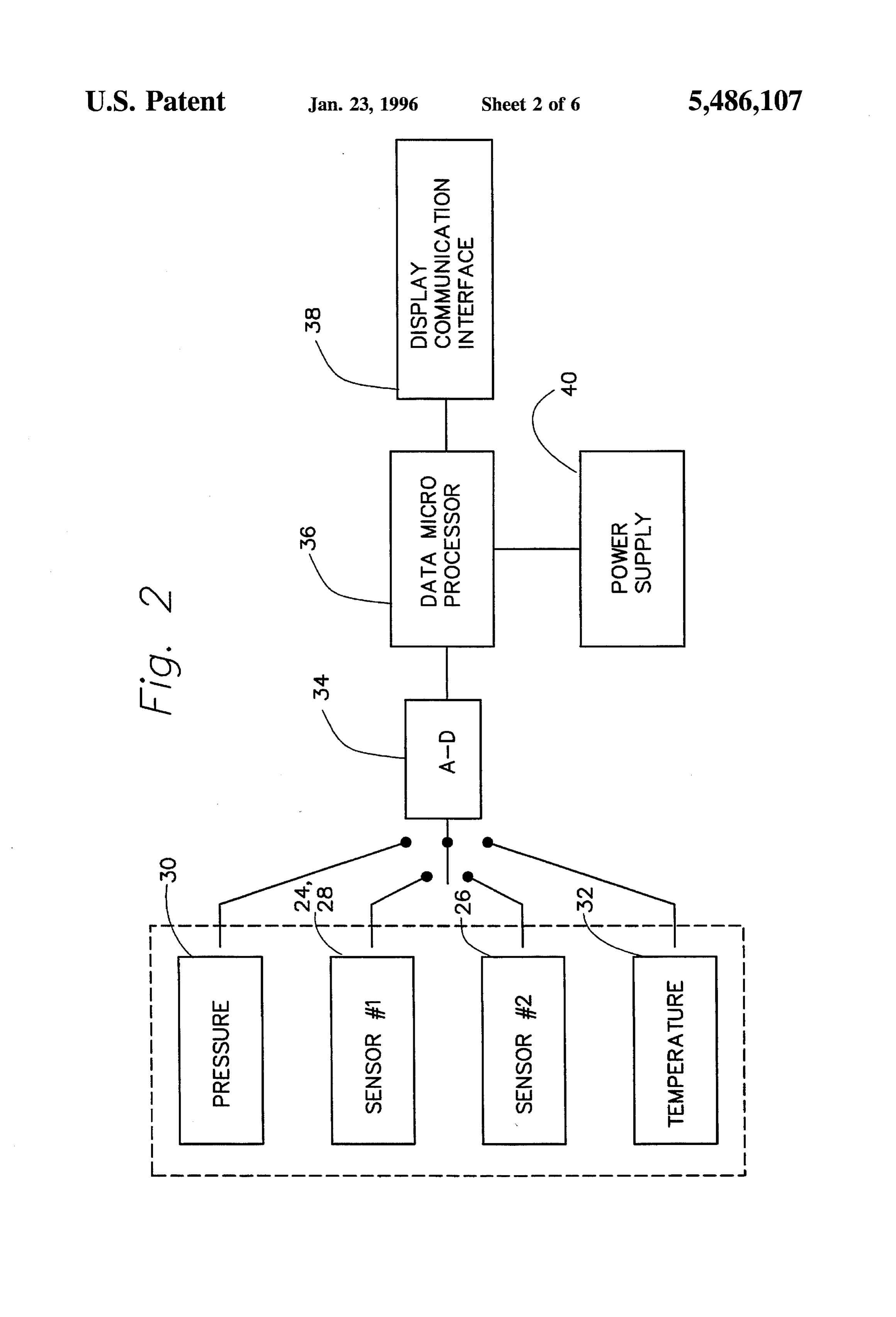
The present invention is directed generally to combustion When the same equation was recently applied to an control and, more particularly, to the improved determina 40 expanded range of gases notably including gases containing tion of fuel characteristics including heating value and nitrogen levels as high as over 20% and containing much oxygen demand and Wobbe Index or Number which can be higher concentrations of ethane, propane, CO and hydro utilized for more accurate fuel metering and combustion gen, however, errors in the determination of heating value control (i.e. efficiency and firing rate) in terms of accurately 45 increased from less than 0.5% to over 12%. This is illus determining the amount of oxygen needed for complete combustion for a given type and amount of fuel which is trated for 78 natural and 22 test gases in FIG. 3. Even after valid for a wide range of fuel compositions and more extensive work in readjusting the empirical coefficients and accurate inasmuch as it is less sensitive to errors in the exponents of the algorithms of the equation 1, the maximum measured parameters from which the values are derived. 50 error has been found to be still over 6%. An error this large still is unsatisfactory for most uses of the higher heating
III. Description of the Related Art value, for the purposes of substantiating amounts charged customers for the heating value of fuel supplied, or fuel-to
The determination of the oxygen demand and heating air ratio combustion control based on oxygen demand mea value, energy content or heat of combustion of a fuel surement. In this regard, any improvement which substan represents an important determination with respect to both 55 tially reduces the error and increases the reliability of the operation of a combustion system with respect to proper determinations of the type involved without adding a great combustion of the fuel and in determining the quantitative deal of cost to the measurement apparatus would be highly commercial value of the fuel with respect to the supplier. In desirable.
this regard, various methods for measuring the heat avail The invention presents a highly accurate on-line system able from fuel gases have been implemented and used for 60 for the determination of the higher heating value H by many purposes. As evidenced by the above-referenced pat monitoring the heat content of gaseous hydrocarbon fuels on ents, the use of spaced microscopic heating and sensing a volumetric basis. In addition, however, knowledge of elements on semiconductor chips to measure certain physi another very important dimension is necessary to account cal parameters in gaseous media is known. These "micro for changes in the specific gravity of the fuel so that a bridge' system are extremely fast reacting, very stable and 65 constant heat input to a pressure fueled burner system can be very sensitive with respect to measuring thermally induced maintained. Thus, for example, while utility companies are changes in electrical resistance when placed in a fluid of very much concerned that the customer be charged precisely
Page 9
for the amount of heat value sold on a volumetric basis, among these values which has been found to be valid and those utilizing the gaseous fuel are also concerned that the more accurate, for a much wider range of fuel compositions Wobbe Number of Index, defined below, be considered so including those with large amounts of higher alkanes, hydro the burner energy input remains constant, whatever the gen and non-combustibles. The present invention provides relative Btu content be on a volumetric basis. This is this accuracy in a manner which exhibits a lower sensitivity especially important in devices that use mass flow devices to measurement errors in obtaining k and c and which is such as orifice meters to measure fuel flow to the burners. capable of readily presenting yield outputs which can be Variations in burner efficiency can be very costly especially utilized for more than one application or usage. Unlike in industrial burner applications for which we need to know previous determinations, the present invention utilizes oxygen demand of the fuel in order to control the fuel/air 10 parameters which are directly measurable, are first con verted to a reference condition of pressure and temperature ratio.
Accordingly, changes in the density or specific gravity of and may not require the measurement of pressure. This has led to a new and more accurate polynomial expression of H, the fuel should be considered in addition to the heating value Wo, or D. The new, more accurate polynomial representa of the fuel on a volumetric flow basis in order to assure tion uses a structure leading to more accurate results. constant heat input to the burners. Such may be accom 15 As indicated above, while earlier expressions of H or D in plished by determining and monitoring the Wobbe Number terms of measured values of k or c, were accurate (i.e. or Index of the fuel, Wo, which is defined as follows: <0.5% error) with respect to pure fuels or fuels having small Wo=Hpo (2) amounts, i.e. less than about 2%, of non-combustibles such as CO or N at higher nitrogen levels, i.e. 20% or more, or 20 higher concentrations of ethane, propane, CO, H, or the where:
H=the higher heating value of the fuel in Btu's/ft joules/ like, the accuracy of such determinations were subject to a great deal more error (>6% even after readjustment of the meter, etc. and coefficients and exponents of the algorithm of equation 1. p=the relative density or specific gravity of the fuel. According to the present invention, it has been found that It is apparent from the above that by considering changes 25 the relationship that exists between H, Wo or D, and k and in the specific gravity of the fuel gas in addition to the c can be expanded to accurately cover a greater variety of heating value on a standard volumetric basis, the Wobbe fuel gases, including those containing large amounts of Index is useful as a measure of the potential heat production alkane hydrocarbons, higher than methane outside the main available for a given burner input. Thus, a fuel mixture of range of conventional fuels and containing higher amounts constant Wobbe Index will provide constant heat input to an 30 of other species including N, CO and H without sacri orifice-controlled burner system. Because of the great varia ficing accuracy of determinations obtained with respect to tion in the heating value of gaseous fuels, the Wobbe Index the other fuel gases. In addition to greatly expanding the has long been used in connection with providing a more variety of accurately determinable fuel gases, the present constant firing rate input to burner systems to produce the invention also makes it readily possible to measure or specified performance and system stability. In the past, 35 determine other thermophysical or thermochemical related however, in order to determine the Wobbe Index of a fuel properties including compressibility (Z), viscosity (n), gas, separate calorimetry and density measurements had to pseudocritical temperature (T) and pseudocritical pressure be made and the results combined. This involved the use of (P), flammability limits, critical compression ratio, flame expensive calorimeters and density meters and required speed and yellow tipping of the flame. considerable time to obtain useable results. It was generally 40 thatAccording
to the present invention, it has been discovered generally universal correlation exists between Y, a not affordable to determine arepresentative real-time Wobbe given property of interest, and the measured microbridge Index on-line control in an industrial setting. properties of thermal conductivity, k, specific heat, c. For diverse applications, the measurement or determina temperature, T, pressure, P (which can also be independently tion of thermophysical or thermochemical related properties is very desirable. These include compressibility (Z), viscos 45 sensed), the derivatives, dk/dT and dc/dT, and ratios ki/k, ity (m), pseudocritical temperature and pressure. Other C1/C2
parameters or fuel properties of interest include flammability A preferred relationship in accordance with the invention limits, critical compression ratio (i.e. the maximum com can be expressed as follows:
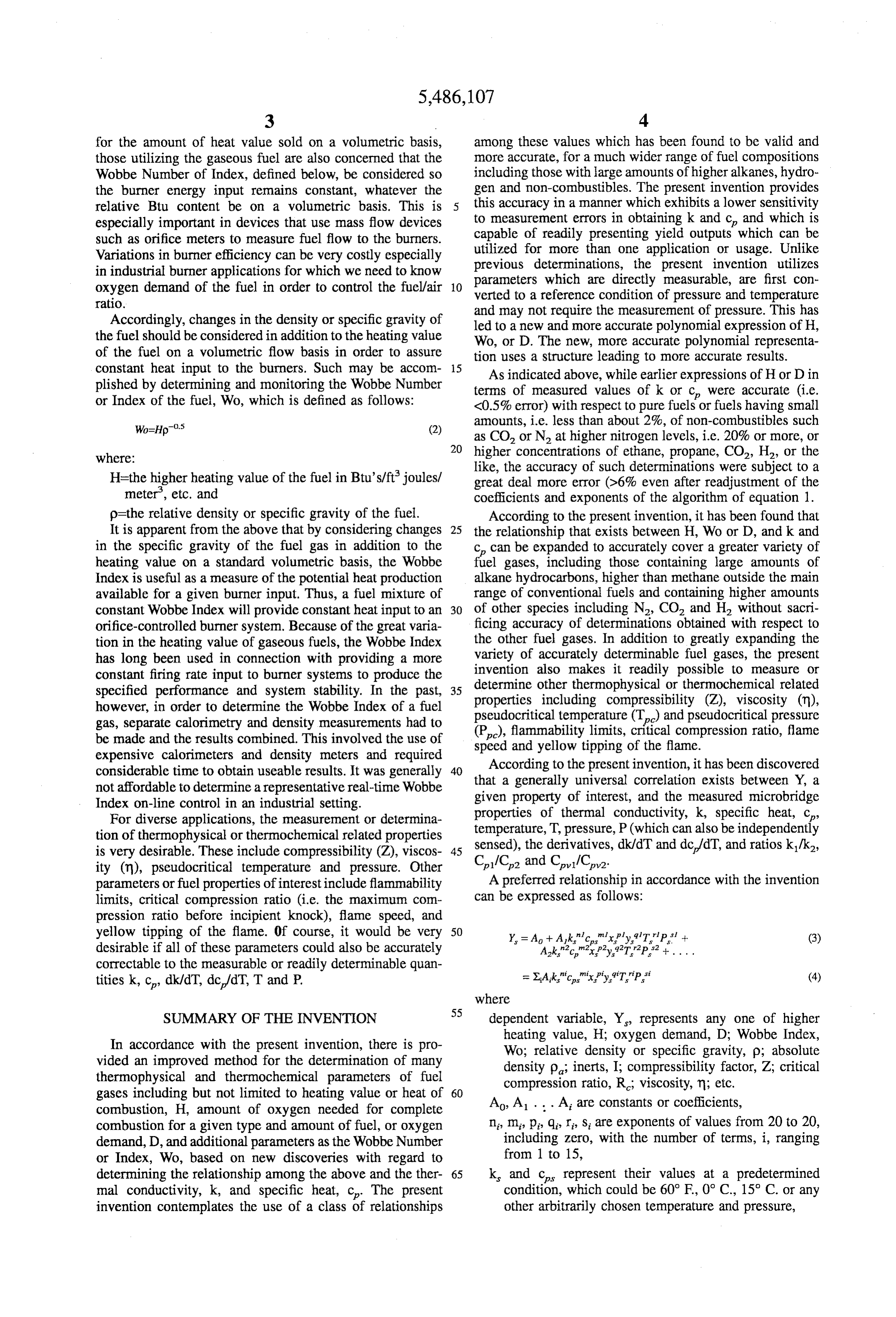
pression ratio before incipient knock), flame speed, and yellow tipping of the flame. Of course, it would be very 50 Y. = A + Ak.c."xply.T.P." + (3) desirable if all of these parameters could also be accurately correctable to the measurable or readily determinable quan tities k, c, dk/dT, dc/dT, T and P.
where
SUMMARY OF THE INVENTION dependent variable, Y, represents any one of higher heating value, H; oxygen demand, D; Wobbe Index,
In accordance with the present invention, there is pro Wo; relative density or specific gravity, p; absolute vided an improved method for the determination of many density p, inerts, I; compressibility factor, Z, critical thermophysical and thermochemical parameters of fuel compression ratio, R.; viscosity, n, etc. gases including but not limited to heating value or heat of 60 combustion, H, amount of oxygen needed for complete Ao, A. . . . A are constants or coefficients, combustion for a given type and amount of fuel, or oxygen n, m, p, q, r s are exponents of values from 20 to 20, demand, D, and additional parameters as the Wobbe Number including zero, with the number of terms, i, ranging or Index, Wo, based on new discoveries with regard to from 1 to 15, determining the relationship among the above and the ther 65 k, and c represent their values at a predetermined mal conductivity, k, and specific heat, c. The present condition, which could be 60°F, 0°C., 15° C. or any invention contemplates the use of a class of relationships other arbitrarily chosen temperature and pressure,
Page 10
x represents dk/dT at the reference condition, FIG. 3 is a graphical representation of a comparison Y represents dc/dT or Cr/C at a reference condi between the actual and computed heating value of 78 gases tion, (o) and 22 test gases (A-V) using a prior correlating rela tionship;
TzT. (the units of c are typically energy per unit of mass FIG. 4 is a graphical representation of a comparison or mole and per AT, while those of c are typically between the actual and computed heating value of the 78 energy per volume and per AT),
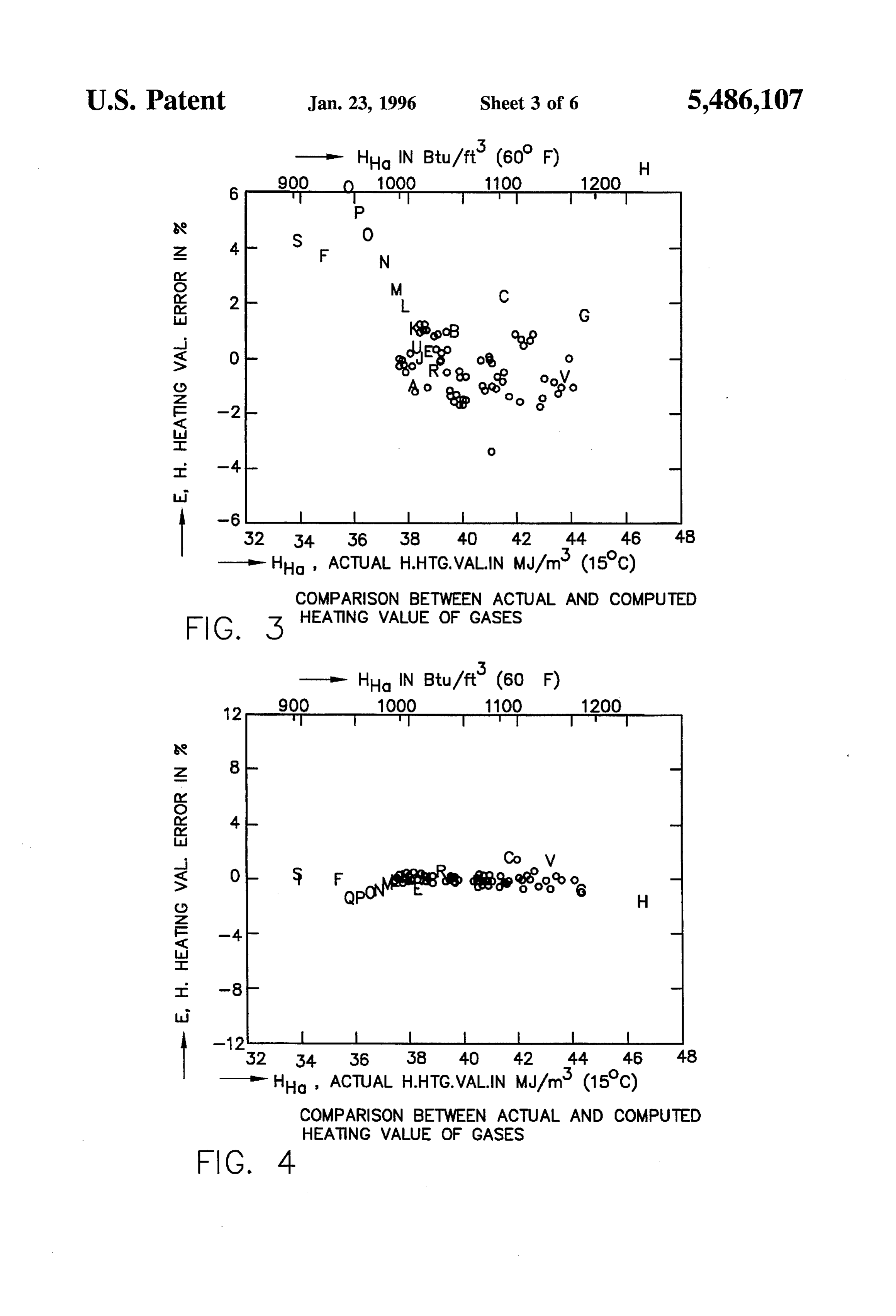
T. represents temperature at said reference condition, natural gases (o) and 22 test gases (A-V) of FIG. 3 using the correlating relationship of the present invention;
P represents absolute pressure at the reference condition. FIG. 5 is a graphical representation of the error in the A preferred method of determining k, and c may be O determination of the compressibility factor for a range of represented by the expressions: gases using the relationship of equation 14 over a range of k=aohak"-a2(k-ki) (T-T) (T-T) (5) temperatures and pressures;
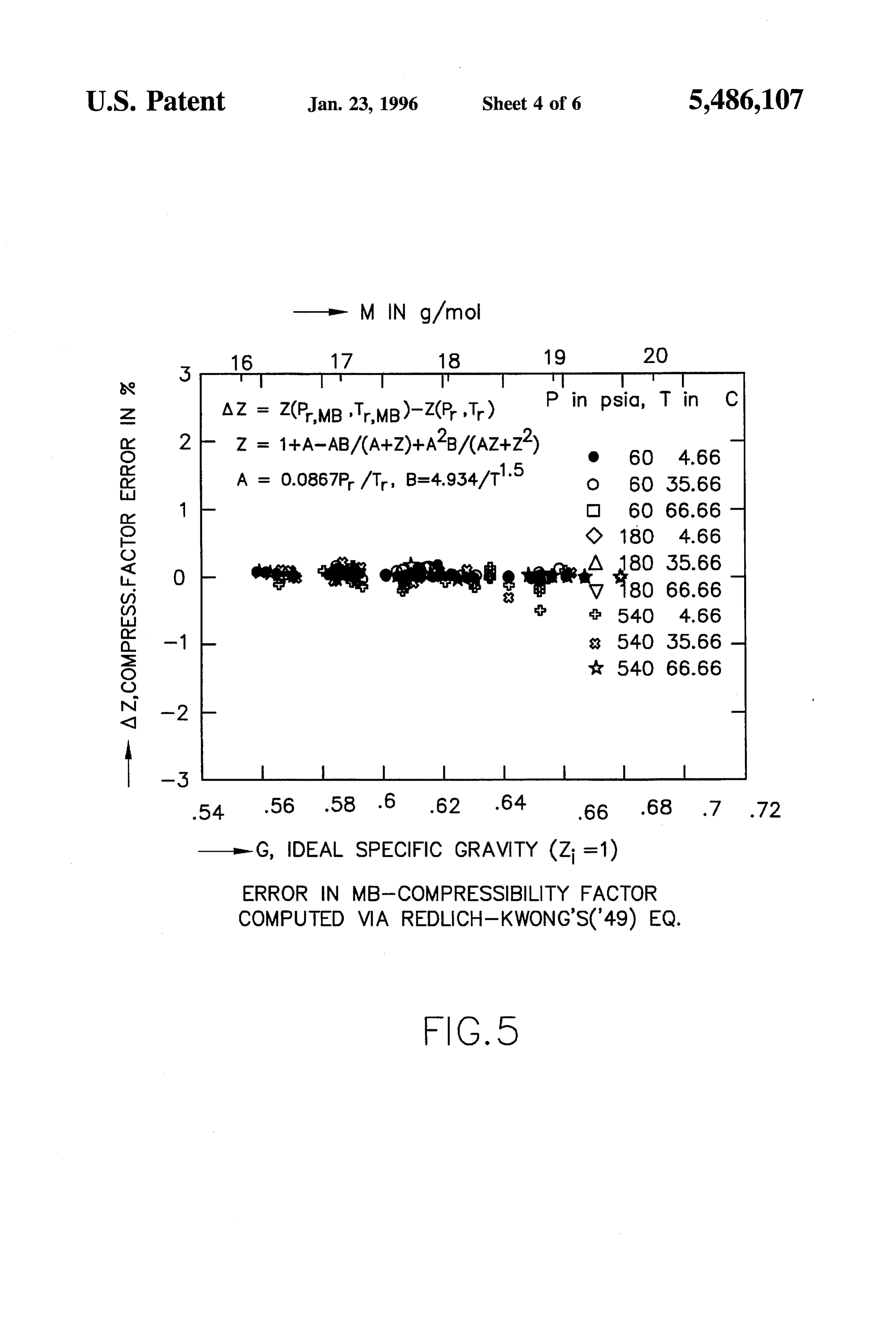
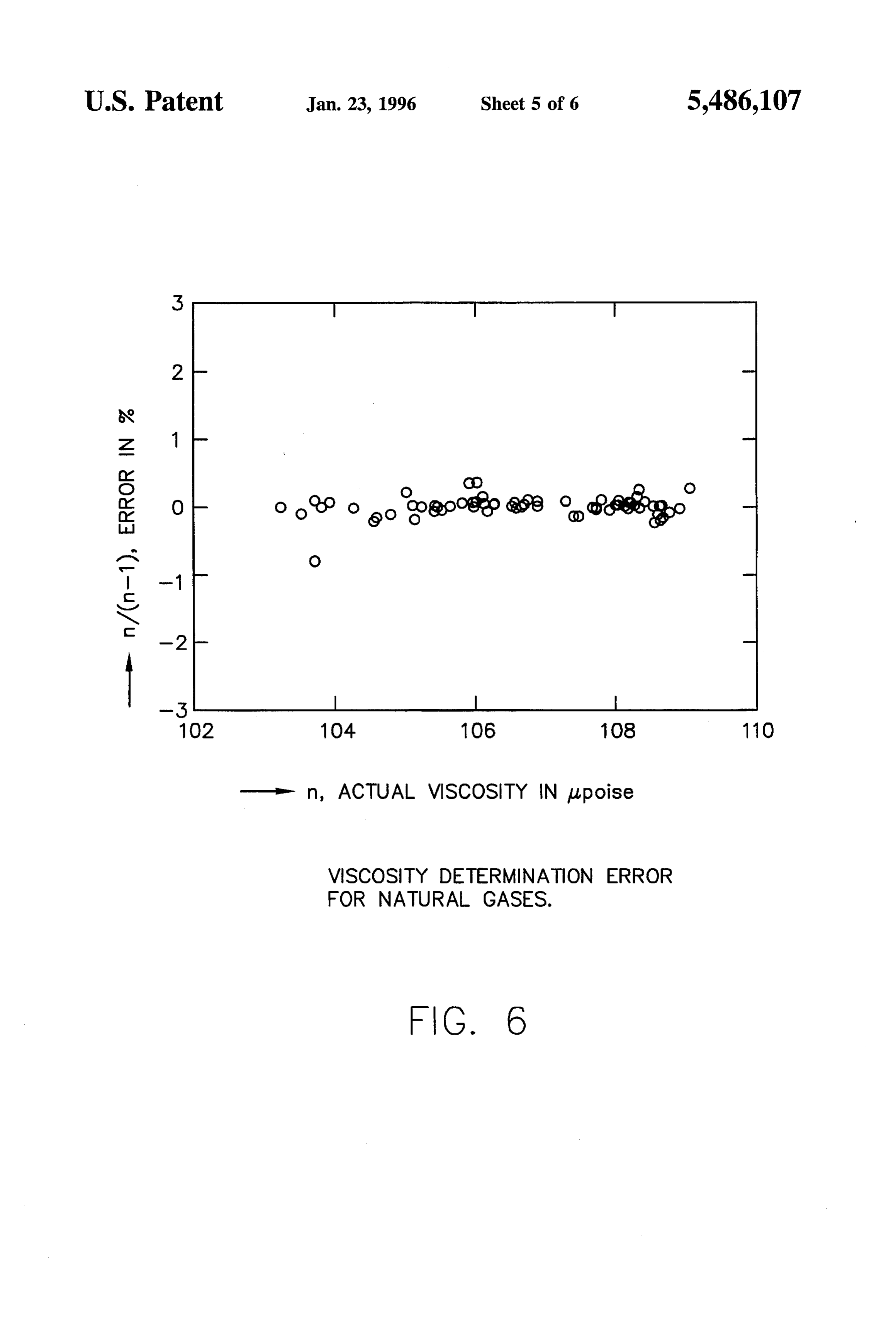
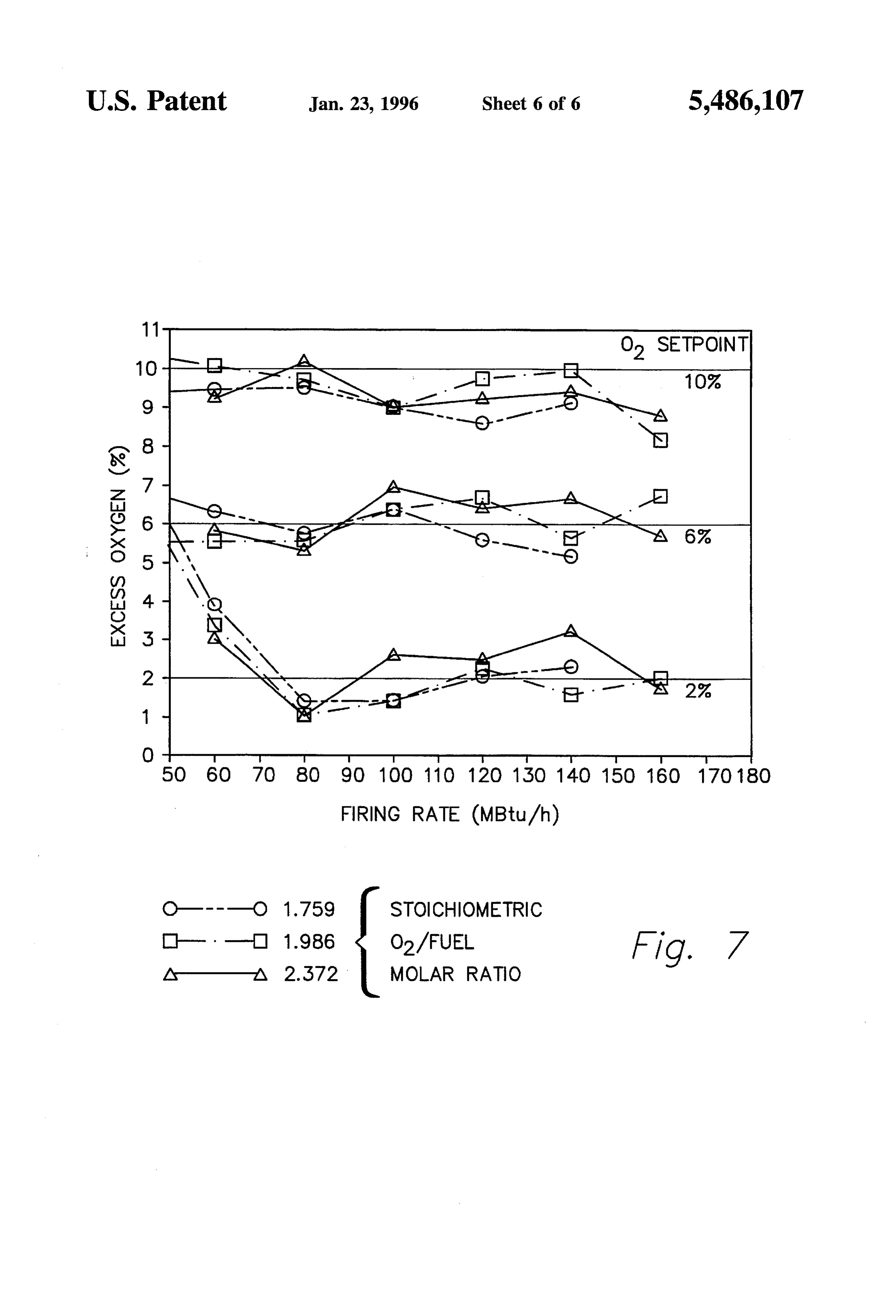
FIG. 6 is a graphical representation of the error in the c=bothic" -b(c. ca) (T-T)/ (T-T) (6) 15 determination of the actual viscosity of the 78 natural gases where based on the relationship of the invention; and FIG. 7 is a graphical representation of actual excess a and b are constants, oxygen control performance at three set points for three m1 and n1 are exponents different fuel gases over a wide range of burner firing rates T and T are temperatures or pressures in a desired range 20 based on the invention.
T is, the standard temperature or pressure.
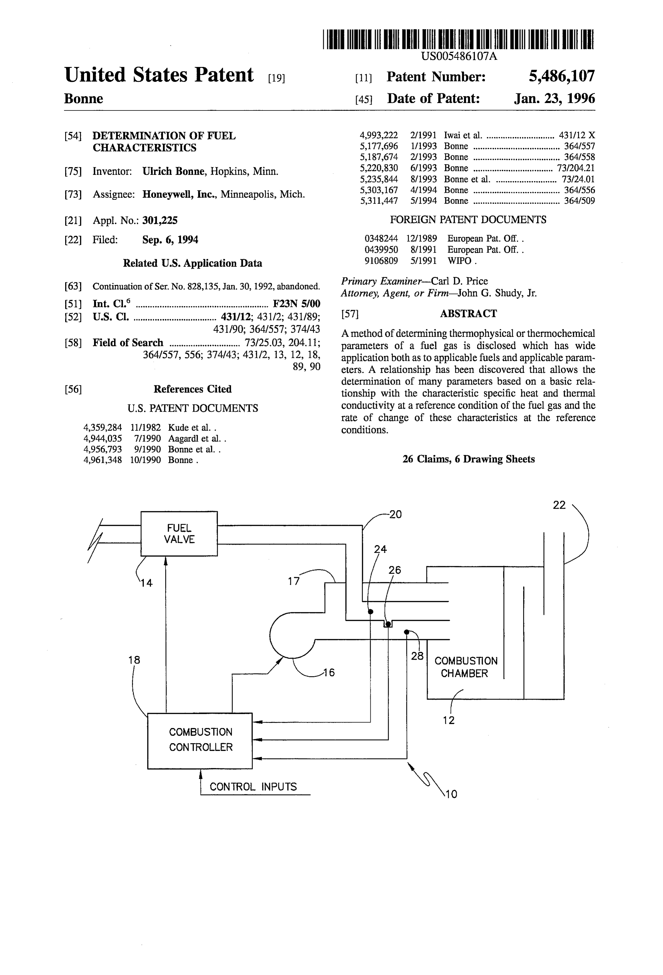
This relation has been found to significantly reduce errors DETALED DESCRIPTION OF THE in k and c as follows: PREFERRED EMBODIMENTS 1) It uses values of at least two measurements of k and c. 25 at different temperatures interpolated or extrapolated to FIG. 1 shows a block diagram of a typical combustion a standard condition increase accuracy. system generally at 10. Heating system 10 includes com 2) Using the ratio of values at different thermodynamic bustion chamber 12, fuel valves 14, air blower 16 and conditions allows one to make use of physical proper combustion controller 18. Fuel enters combustion chamber ties that are largely or more independent of such 12 through fuel conduit 20 where it is combined with air thermodynamic condition (e.g. varying the temperature blown from air blower 16. The fuel and air mixture is ignited at constant pressure for crific eliminates the pres in combustion chamber 12 and resulting flue gases exit sure influence of c, whereas it would not be eliminated combustion chamber 12 through flue 22. by simply using dc/dT). Combustion controller 18 controls the fuel-to-air mixture 3) Even more accuracy may be available if the relation is 35 invalves combustion chamber 12 by opening and closing fuel 14 and by opening and closing air dampers in air fitted individually to a series of limited ranges of conduit 17. Combustion controller 18 controls the fuel-to-air parameter values which might include two or more ranges for any of the involved parameters; for example, mixture based on control inputs entered by a heating system in a simple case of two ranges of fuel gas heating values operator as well as sensor inputs received from sensors 24 one might select H>1050 Btu/ft and HZ1050 Btu/ft. 40 and 26 in fuel conduit 20, and sensor 28 in air conduit 17. Thus, the Ypolynomial can then be optimized for each Sensors 24 and 28 are typically microbridge or microan given range. Depending on the application, any number emometer sensors which communicate with flowing fuel in of relatively limited ranges can be implemented. fuel conduit 20 and flowing air in air conduit 17. This type As more fully described in the above-referenced Bonne, of sensor is described in more detail in the above-referenced et al. (U.S. Pat. No. 4956 793) patent, the relative density, 45 application Ser. No. 285,890.
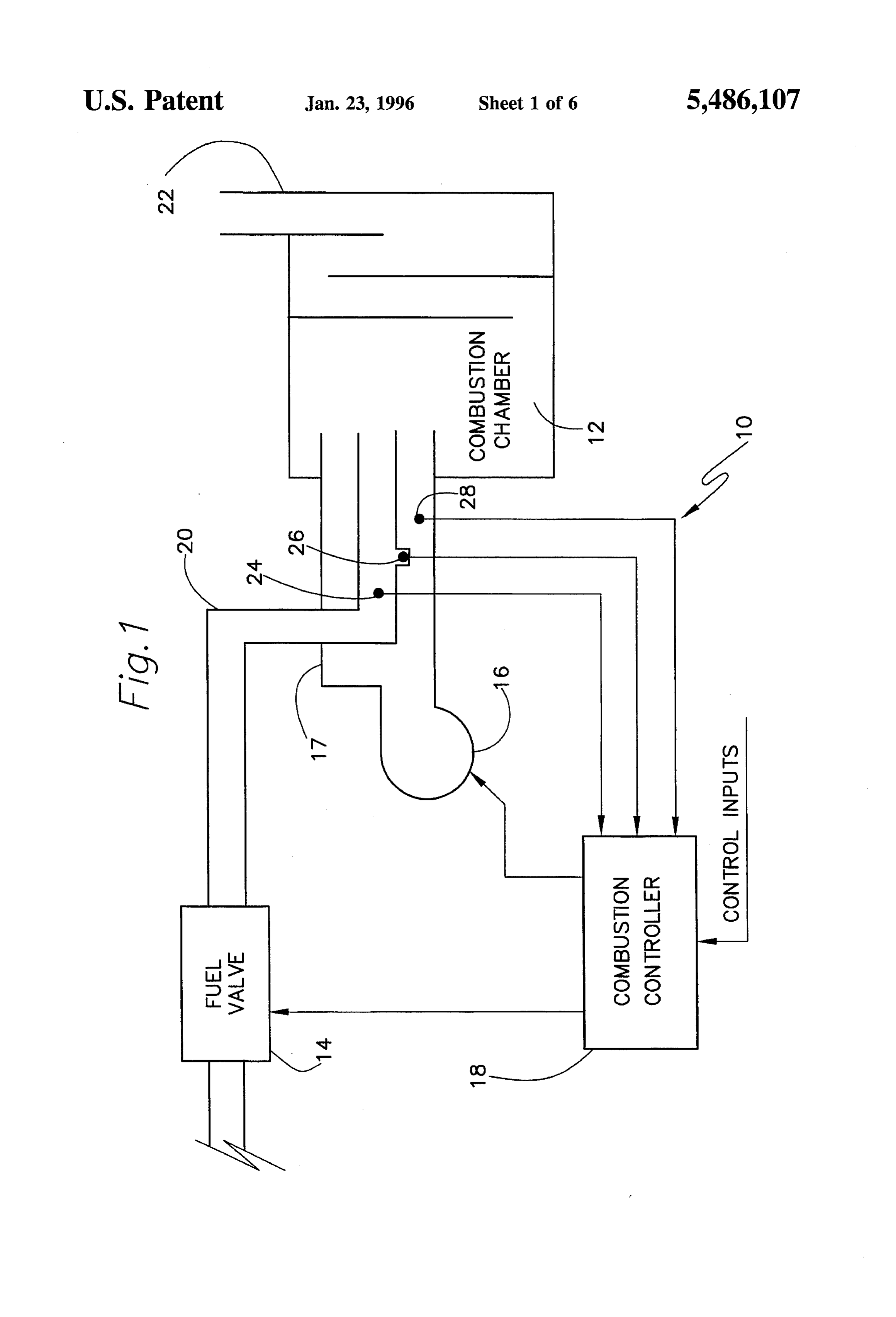
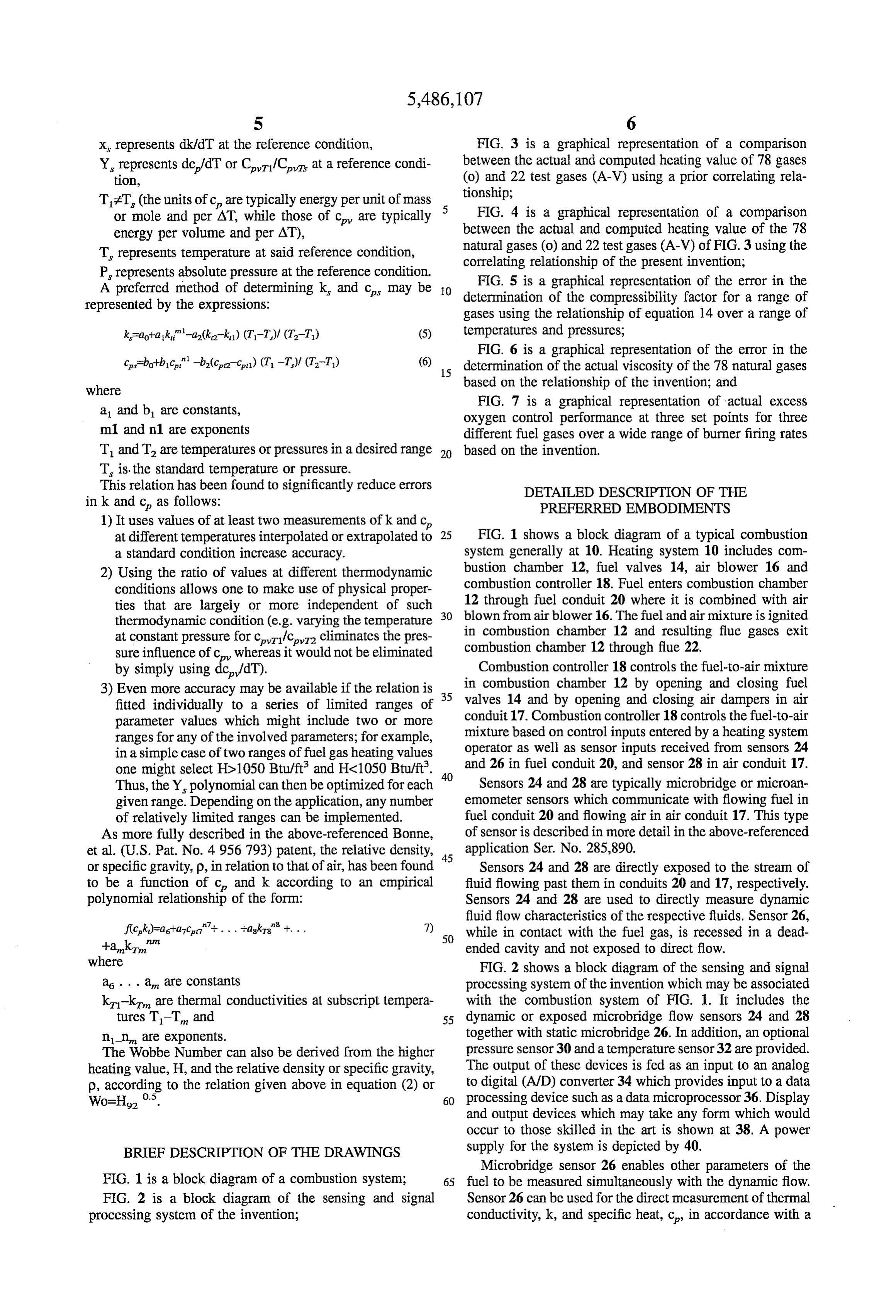
or specific gravity, p, in relation to that of air, has been found Sensors 24 and 28 are directly exposed to the stream of to be a function of c, and k according to an empirical fluid flowing past them in conduits 20 and 17, respectively. polynomial relationship of the form: Sensors 24 and 28 are used to directly measure dynamic fluid flow characteristics of the respective fluids. Sensor 26, fick)-asha, cer"+ ... +agkas" +... 7) 50 while in contact with the fuel gas, is recessed in a dead +ank." ended cavity and not exposed to direct flow. where FIG. 2 shows a block diagram of the sensing and signal as . . . a are constants processing system of the invention which may be associated k-ki are thermal conductivities at Subscript tempera with the combustion system of FIG. 1. It includes the tures T-T and 55 dynamic or exposed microbridge flow sensors 24 and 28 n_n are exponents. together with static microbridge 26. In addition, an optional The Wobbe Number can also be derived from the higher pressure sensor 30 and a temperature sensor 32 are provided. heating value, H, and the relative density or specific gravity, The output of these devices is fed as an input to an analog p, according to the relation given above in equation (2) or to digital (AWD) converter 34 which provides input to a data Wo=H0. 60 processing device such as a data microprocessor 36. Display and output devices which may take any form which would occur to those skilled in the art is shown at 38. A power
BRIEF DESCRIPTION OF THE DRAWINGS supply for the system is depicted by 40. Microbridge sensor 26 enables other parameters of the
FIG. 1 is a block diagram of a combustion system; 65 fuel to be measured simultaneously with the dynamic flow. FIG. 2 is a block diagram of the sensing and signal Sensor 26 can be used for the direct measurement of thermal processing system of the invention; conductivity, k, and specific heat, c, in accordance with a
Page 11
technique which allows the accurate determination of both Wo; relative density or specific gravity, p; absolute properties. That technique contemplates generating an density p, inerts, I; compressibility factor, Z; critical energy or temperature pulse in one or more heater elements compression ratio, R., viscosity, , etc. disposed in and closely coupled to the fluid medium in Ao, A. . . At are constants or coefficients, conduit 20. Characteristic values of k and c of the fluid in n, m, P., q, r, s are exponents of values from -20 to 20, conduit 20 then cause corresponding changes in the time variable temperature response of the heater to the tempera including Zero, with the number of terms, i, ranging ture pulse. Under relatively static fluid flow conditions this, from 1 to 15, in turn, induces corresponding changes in the time variable k, and c represent their values at a predetermined response of more temperature responsive sensors coupled to 10 condition, which could be 60° F 0° C., 15° C. or any the heater principally via the fluid medium in conduit 20. other arbitrarily chosen temperature and pressure, The thermal pulse need be only of sufficient duration that x, represents dk/dT at the reference condition, the heater achieve a substantially steady-state temperature Y represents dc/dT or cer/car at a reference condi for a short time. Such a system of determining thermal tion, TzT (the units of care typically energy per unit conductivity, k, and specific heat, c, is described in greater detail in above-referenced patents A. 56793 and 4944035. 15 of mass or mole and per AT, while those of cy are typically energy per volume and per AT),
It has also been found that once the specific heat and T represents temperature at said reference condition, thermal conductivity of the fluid have been determined, they can be used to determine the density or specific gravity of P represents absolute pressure at the reference condition. the fluid. As described above, this technique is more spe 20 inas which the needed values of k, and c are determined cifically illustrated and described in U.S. Pat. No. 4956 793. in
Of course, these parameters can be determined by other means if such are desirable in other applications. kaohak"-b(k2-ka) (tr. t.)/(1-t) (5) Once k and c or c of a gas or fluid are known, flow co-hot-bic -b2(c.2-c pa)(1-t)/(2-ti) (6) correction factors in the form of simple, constant flow independent factors for the fuel can be calculated and used. 25 where a and are constants
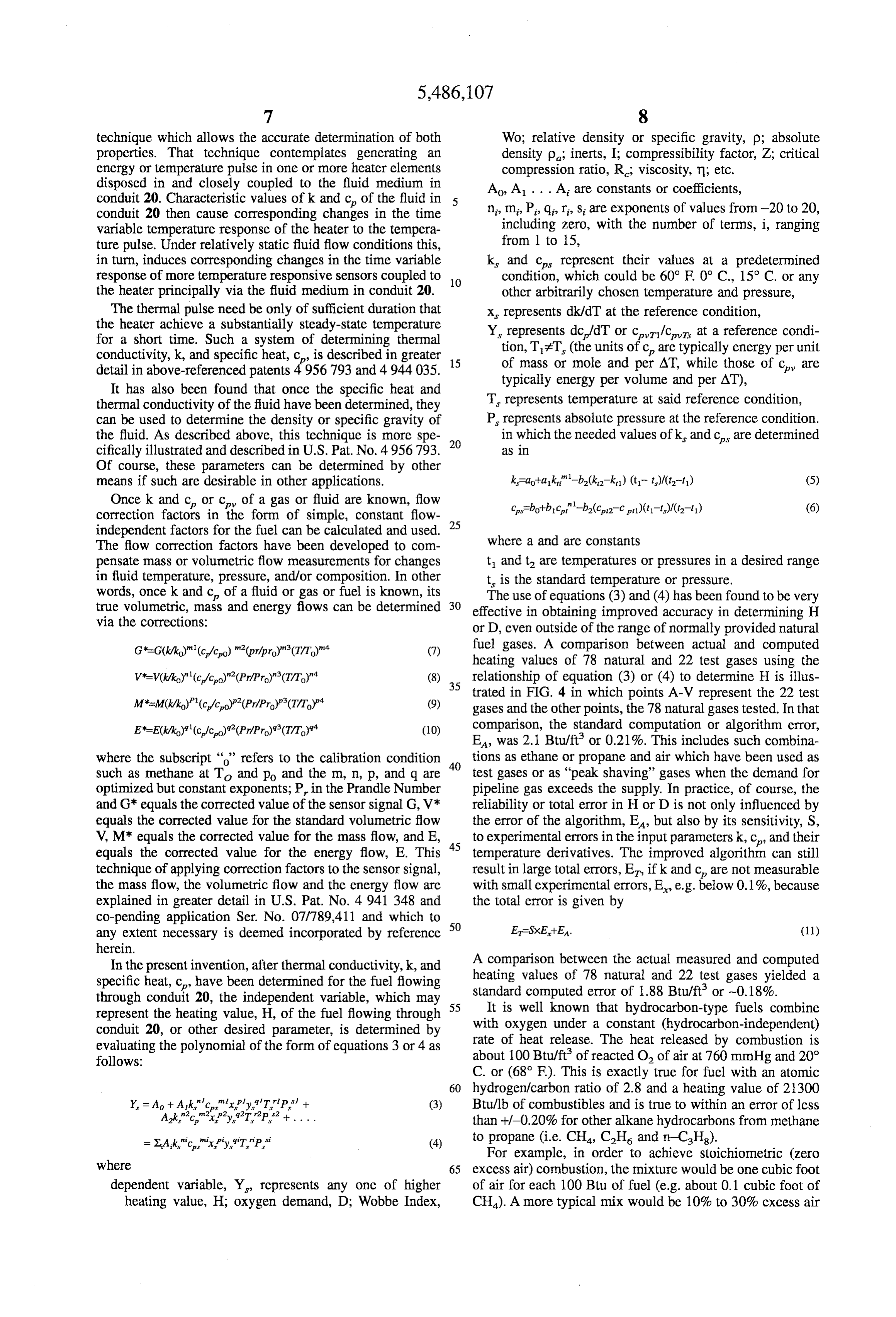
The flow correction factors have been developed to com pensate mass or volumetric flow measurements for changes t and t are temperatures or pressures in a desired range in fluid temperature, pressure, and/or composition. In other t is the standard temperature or pressure. words, once k and c of a fluid or gas or fuel is known, its 30 The use of equations (3) and (4) has been found to be very true volumetric, mass and energy flows can be determined effective in obtaining improved accuracy in determining H via the corrections: or D, even outside of the range of normally provided natural fuel gases. A comparison between actual and computed heating values of 78 natural and 22 test gases using the
relationship of equation (3) or (4) to determine H is illus trated in FIG. 4 in which points A-V represent the 22 test gases and the other points, the 78 natural gases tested. In that comparison, the standard computation or algorithm error,
EA, was 2.1 Btu/ft or 0.21%. This includes such combina where the subscript “” refers to the calibration condition 40 tions as ethane or propane and air which have been used as such as methane at T and po and the m, n, p, and q are test gases or as "peak shaving' gases when the demand for optimized but constant exponents; P in the Prandle Number pipeline gas exceeds the Supply. In practice, of course, the and G* equals the corrected value of the sensor signal G, V* reliability or total error in H or D is not only influenced by equals the corrected value for the standard volumetric flow the error of the algorithm, EA, but also by its sensitivity, S, V, M* equals the corrected value for the mass flow, and E, 45 to experimental errors in the input parameters k, Cp and their equals the corrected value for the energy flow, E. This temperature derivatives. The improved algorithm can still technique of applying correction factors to the sensor signal, result in large total errors, Er, if k and c are not measurable the mass flow, the volumetric flow and the energy flow are with small experimental errors, E, e.g. below 0.1%, because explained in greater detail in U.S. Pat. No. 4941 348 and the total error is given by co-pending application Ser. No. 07/789,411 and which to any extent necessary is deemed incorporated by reference 50 E=SXE+Ea. (11) herein.
In the present invention, after thermal conductivity, k, and A comparison between the actual measured and computed specific heat, c, have been determined for the fuel flowing heating values of 78 natural and 22 test gases yielded a through conduit 20, the independent variable, which may 55 standard computed error of 1.88 Btu/ft or -0.18%. represent the heating value, H., of the fuel flowing through It is well known that hydrocarbon-type fuels combine conduit 20, or other desired parameter, is determined by with oxygen under a constant (hydrocarbon-independent) evaluating the polynomial of the form of equations 3 or 4 as rate of heat release. The heat released by combustion is follows: about 100 Btu/ft of reacted O, of air at 760 mmHg and 20° C. or (68°F). This is exactly true for fuel with an atomic 60 hydrogen/carbon ratio of 2.8 and a heating value of 21300 (3) Btu/lb of combustibles and is true to within an error of less than +/-0.20% for other alkane hydrocarbons from methane =XAk"c"xply.T.P. (4) to propane (i.e. CH, CH and n-CH).
where
For example, in order to achieve stoichiometric (zero 65 excess air) combustion, the mixture would be one cubic foot dependent variable, Y, represents any one of higher of air for each 100 Btu of fuel (e.g. about 0.1 cubic foot of heating value, H, oxygen demand, D; Wobbe Index, CH). A more typical mix would be 10% to 30% excess air
Page 12
which would require 1.1 to 1.3 cubic feet of air for each 100 This, in turn, is related to that at a standard temperature Btu of fuel. This would be a typical mixture because and pressure (O.C., 1 Atmosphere), V and the actual gas residential appliances typically operate in the 40-100% density p is determined from excess air range while most commercial combustion units papViro/VM (13) operate between 10 and 50% excess air.
Although the present invention has been described with where reference to fuels with hydrocarbon constituents, the present po is a constant equal to the density of the air at standard invention can be used to control the fuel-to-air ratio for other conditions (0 C. and 1 Atmosphere), fuels. Each fuel used in combustion requires or demands a pA is the absolute specific gravity, certain amount of oxygen for complete and efficient com 10 .bustion (i.e. little or no fuel or oxygen remaining after V is a constant equal to the molar volume at standard combustion). The amount of oxygen required by each fuel is temperature air pressure, i.e. ~22.4 l/m and the oxygen demand value D for that fuel. D, then, is defined V is the actual molar volume at the temperature and as units of moles of O. needed by each mole of fuel for 15 pressure of measurement.
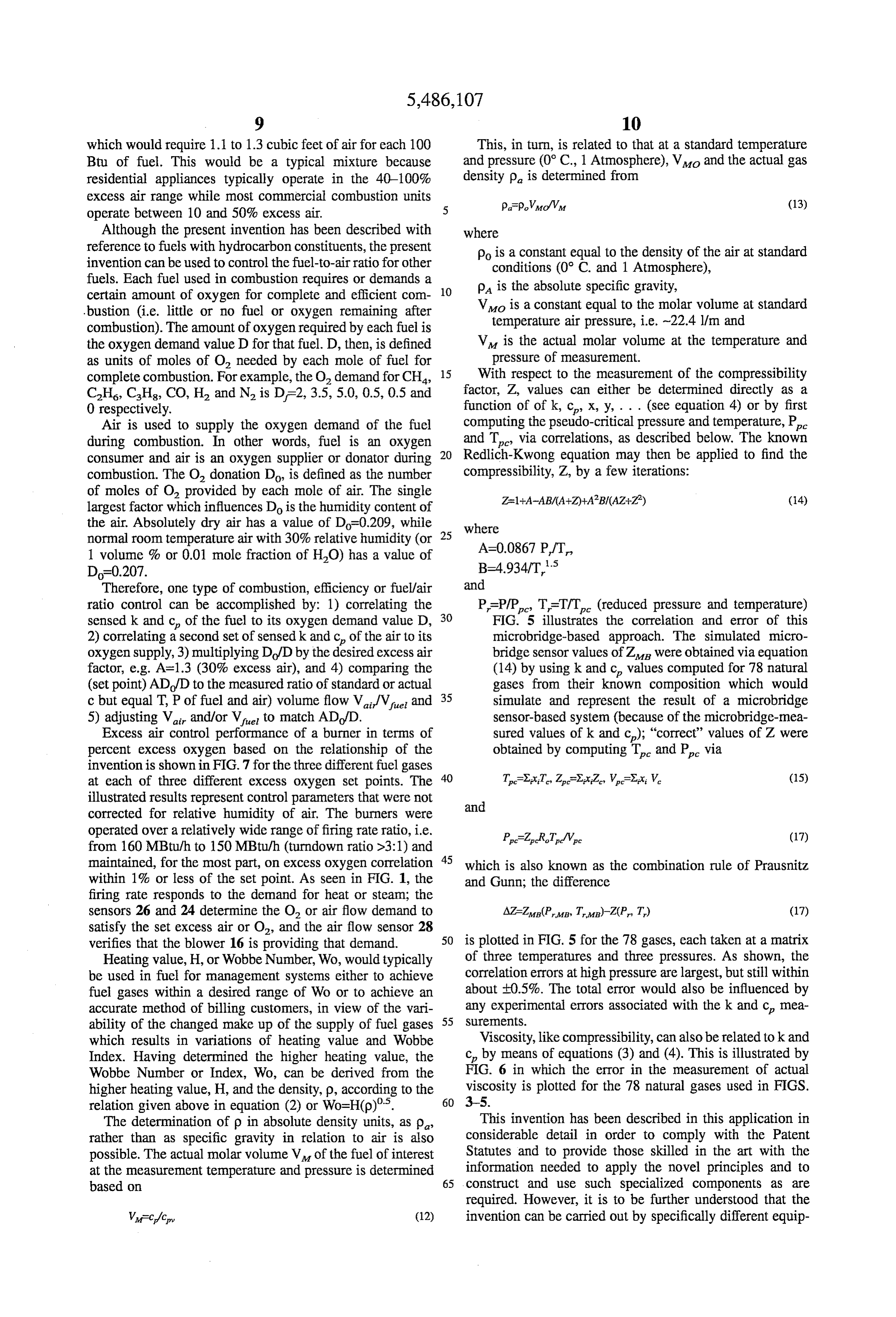
complete combustion. For example, the Odemand for CH, With respect to the measurement of the compressibility C2H6, CHs, CO, H2 and N2 is D-2, 3.5, 5.0, 0.5,0.5 and factor, Z, values can either be determined directly as a 0 respectively. function of of k, c, x, y, . . . (see equation 4) or by first Air is used to supply the oxygen demand of the fuel computing the pseudo-critical pressure and temperature, P. during combustion. In other words, fuel is an oxygen and Te via correlations, as described below. The known consumer and air is an oxygen supplier or donator during 20 Redlich-Kwong equation may then be applied to find the combustion. The O. donation Do is defined as the number compressibility, Z., by a few iterations:
of moles of O provided by each mole of air. The single largest factor which influences Do is the humidity content of the air. Absolutely dry air has a value of Do-0.209, while 25 where normal room temperature air with 30% relative humidity (or 1 volume % or 0.01 mole fraction of HO) has a value of A=0.0867 P/T,
D=0.207. B=4934/T's
Therefore, one type of combustion, efficiency or fuel/air and ratio control can be accomplished by: 1) correlating the P-PIP, T-TT (reduced pressure and temperature) sensed k and c of the fuel to its oxygen demand value D, 30 FIG. 5 illustrates the correlation and error of this 2) correlating a second set of sensed k and c of the air to its microbridge-based approach. The simulated micro oxygen supply, 3) multiplying Do/D by the desired excess air bridge sensor values of Z were obtained via equation factor, e.g. A=1.3 (30% excess air), and 4) comparing the (14) by using k and c values computed for 78 natural (set point) AD/D to the measured ratio of standard or actual gases from their known composition which would c but equal T, P of fuel and air) volume flow V/V, and 35 simulate and represent the result of a microbridge 5) adjusting V and/or V to match ADo/D. sensor-based system (because of the microbridge-mea Excess air control performance of a burner in terms of sured values of k and c); "correct" values of Z were percent excess oxygen based on the relationship of the obtained by computing T and P. via invention is shown in FIG.7 for the three different fuel gases at each of three different excess oxygen set points. The 40 TXx:T, ZXx:Z, WXX, W. (15) illustrated results represent control parameters that were not and corrected for relative humidity of air. The burners were operated over a relatively wide range of firing rate ratio, i.e. P-ZRT/Vc (17) from 160 MBtu/h to 150 MBtu/h (turndown ratio >3:1) and maintained, for the most part, on excess oxygen correlation 45 which is also known as the combination rule of Prausnitz within 1% or less of the set point. As seen in FIG. 1, the and Gunn, the difference firing rate responds to the demand for heat or steam; the sensors 26 and 24 determine the O or air flow demand to AZ-Zug (Pug Tan)-Z(P. T.) (17) satisfy the set excess air or O, and the air flow sensor 28 verifies that the blower 16 is providing that demand. 50 is plotted in FIG. 5 for the 78 gases, each taken at a matrix Heating value, H, or Wobbe Number, Wo, would typically of three temperatures and three pressures. As shown, the be used in fuel for management systems either to achieve correlation errors at high pressure are largest, but still within fuel gases within a desired range of Wo or to achieve an about E0.5%. The total error would also be influenced by accurate method of billing customers, in view of the vari any experimental errors associated with the k and c, mea ability of the changed make up of the supply of fuel gases 55 SurementS.
which results in variations of heating value and Wobbe Viscosity, like compressibility, can also be related to k and Index. Having determined the higher heating value, the c by means of equations (3) and (4). This is illustrated by Wobbe Number or Index, Wo, can be derived from the FIG. 6 in which the error in the measurement of actual higher heating value, H, and the density, p, according to the viscosity is plotted for the 78 natural gases used in FIGS. relation given above in equation (2) or Wo=H(p)'. 60 3-5.
The determination of p in absolute density units, as p This invention has been described in this application in rather than as specific gravity in relation to air is also considerable detail in order to comply with the Patent possible. The actual molar volume V of the fuel of interest Statutes and to provide those skilled in the art with the at the measurement temperature and pressure is determined information needed to apply the novel principles and to based on 65 construct and use such specialized components as are required. However, it is to be further understood that the
Wife/cy (12) invention can be carried out by specifically different equip
Page 13
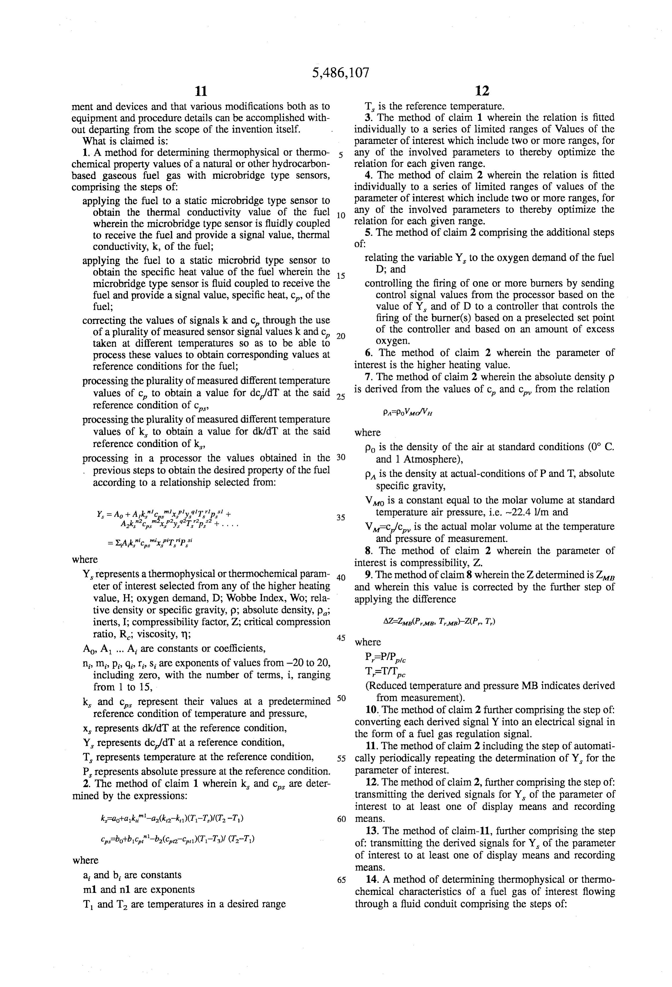
ment and devices and that various modifications both as to T is the reference temperature. equipment and procedure details can be accomplished with 3. The method of claim 1 wherein the relation is fitted out departing from the scope of the invention itself. individually to a series of limited ranges of Values of the What is claimed is: parameter of interest which include two or more ranges, for 1. A method for determining thermophysical or thermo any of the involved parameters to thereby optimize the chemical property values of a natural or other hydrocarbon relation for each given range. based gaseous fuel gas with microbridge type sensors, 4. The method of claim 2 wherein the relation is fitted comprising the steps of: individually to a series of limited ranges of values of the applying the fuel to a static microbridge type sensor to parameter of interest which include two or more ranges, for obtain the thermal conductivity value of the fuel 10 any of the involved parameters to thereby optimize the wherein the microbridge type sensor is fluidly coupled relation for each given range.
to receive the fuel and provide a signal value, thermal 5. The method of claim 2 comprising the additional steps conductivity, k, of the fuel; of:
applying the fuel to a static microbrid type sensor to relating the variable Y to the oxygen demand of the fuel obtain the specific heat value of the fuel wherein the 15 D; and microbridge type sensor is fluid coupled to receive the controlling the firing of one or more burners by sending fuel and provide a signal value, specific heat, c, of the control signal values from the processor based on the fuel; value of Y and of D to a controller that controls the correcting the values of signals k and c, through the use firing of the burner(s) based on a preselected set point of a plurality of measured sensor signal values k and c, of the controller and based on an amount of excess taken at different temperatures so as to be able to OXygen.
process these values to obtain corresponding values at 6. The method of claim 2 wherein the parameter of reference conditions for the fuel; interest is the higher heating value. processing the plurality of measured different temperature 7. The method of claim 2 wherein the absolute density p values of c, to obtain a value for dc/dT at the said 25 is derived from the values of c, and c, from the relation reference condition of c, papoViro/Vu processing the plurality of measured different temperature values of k, to obtain a value for dk/dT at the said where reference condition of k, po is the density of the air at standard conditions (0° C. processing in a processor the values obtained in the 30 and 1 Atmosphere), previous steps to obtain the desired property of the fuel pA is the density at actual-conditions of P and T, absolute according to a relationship selected from: specific gravity,
Vo is a constant equal to the molar volume at standard
Y. P Ao -- Ak r myPy. Trip. --
is 35 temperature air pressure, i.e. --22.4 l/m and
Ak'c."'s P'y'T. p + . . . . V=c/c is the actual molar volume at the temperature =XAk"c." PT.P." and pressure of measurement.
where 8. The method of claim 2 wherein the parameter of interest is compressibility, Z.
Y represents athermophysical orthermochemical param 40 9. The method of claim 8 wherein the Z determined is Z. eter of interest selected from any of the higher heating and wherein this value is corrected by the further step of value, H; oxygen demand, D; Wobbe Index, Wo; rela applying the difference tive density or specific gravity, p, absolute density, p, inerts, I; compressibility factor, Z; critical compression AZ-Zug (PMB, TMB)-Z(P. T.) ratio, R.; viscosity, n; 45 where
Ao, A. A. are constants or coefficients, n, m, p, q, r, s are exponents of values from -20 to 20, P=P/P.
including Zero, with the number of terms, i, ranging T=T/T.
from 1 to 15, (Reduced temperature and pressure MB indicates derived k, and c represent their values at a predetermined 50 from measurement).
reference condition of temperature and pressure, 10. The method of claim 2 further comprising the step of: x represents dk/dT at the reference condition, converting each derived signal Y into an electrical signal in the form of a fuel gas regulation signal.
Y, represents dc/dT at a reference condition, 11. The method of claim 2 including the step of automati T. represents temperature at the reference condition, 55 cally periodically repeating the determination of Y for the P represents absolute pressure at the reference condition. parameter of interest.
12. The method of claim 2, further comprising the step of:
2. The method of claim 1 wherein k, and c are deter transmitting mined by the expressions: the derived signals for Y of the parameter of interest to at least one of display means and recording
13. The method of claim-11, further comprising the step of transmitting the derived signals for Y of the parameter where of interest to at least one of display means and recording
at and b, are constants 65 14. A method of determining thermophysical or thermo m1 and n1 are exponents chemical characteristics of a fuel gas of interest flowing T and T are temperatures in a desired range through a fluid conduit comprising the steps of:
Page 14
(a) conducting at least a partial stream of the fuel gas 17. The method of claim 14 including the step of auto through a sensor chamber having one or more sensors matically periodically repeating the determination of Y for in contact with the fuel gas; the parameter of interest.
(b) generating a first electrical signal indicative of tem- 18. The method of claim 14, further comprising the step perature of the fuel gas; 5 of transmitting the derived signals for Y of the parameter (c) generating a second electrical signal at a sensor in of interest to at least one of display means and recording contact with the fuel gas, the first electrical signal being caS.
representative of a first fuel gas quality, the first fuel gas 19. The method of claim 14, further comprising the step quality comprising one of the thermal conductivity and of: transmitting the derived signals for Y of the parameter specific heat; 10 of interest to at least one of display means and recording (d) conducting the first electrical signal to a computing CaS.
means, 20. A method for determining thermophysical or thermo (e) generating a third electrical signal at a sensor in chemical property values of a natural or other hydrocarbon contact with the fuel gas, the third electrical signal based gaseous fuel gas comprising the steps of: being representative of a second fuel gas quality, the 15 obtaining the thermal conductivity value of the fuel second fuel gas quality comprising one of the thermal through the use of a static microbridge type sensor conductivity and specific heat, the second gas quality located so as to be closely coupled with the fuel and comprising a different one of the fuel gas qualities than provide an output of a signal value, k, representative of the first gas quality; the sensor perceived;
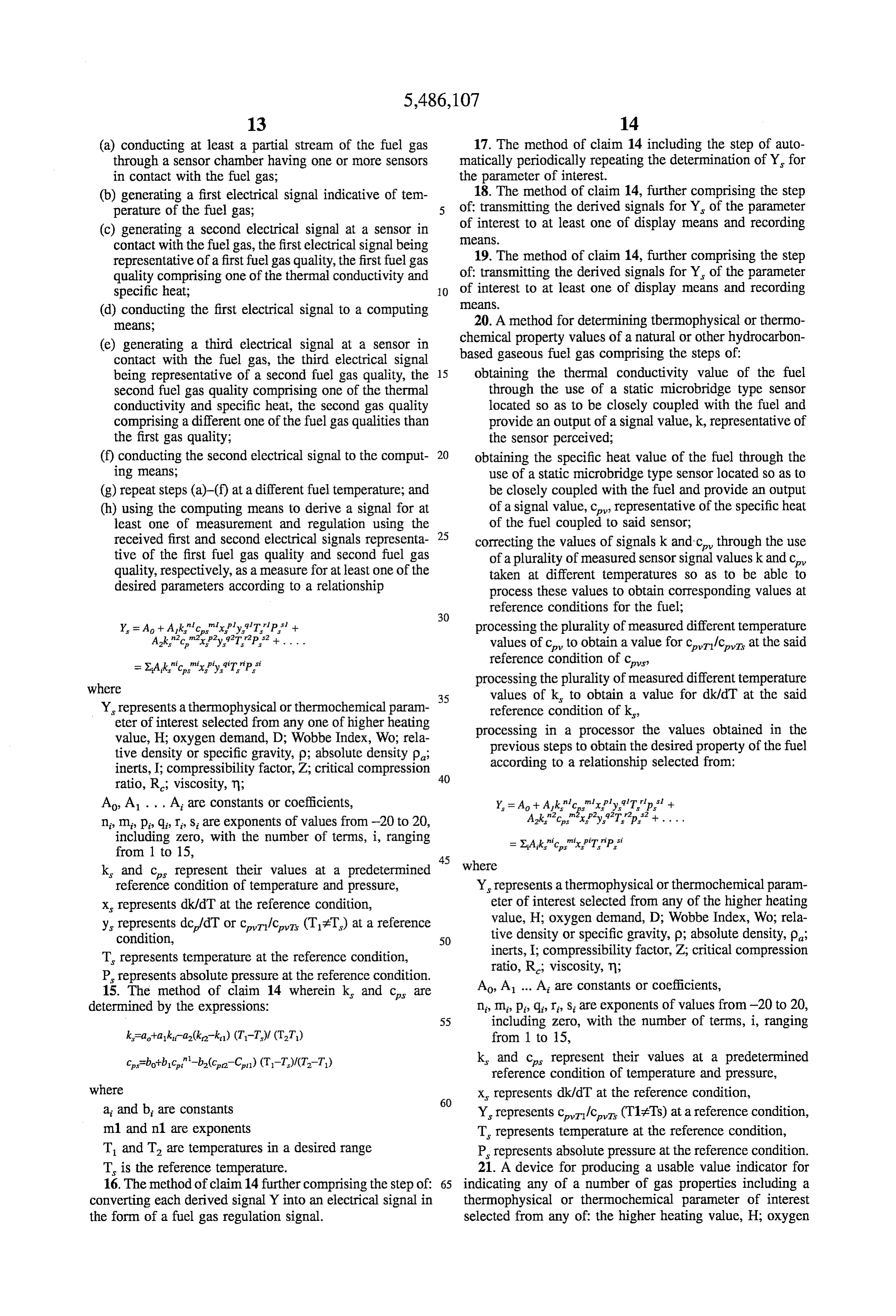
(f) conducting the second electrical signal to the comput- 20 obtaining the specific heat value of the fuel through the ing means; use of a static microbridge type sensor located so as to (g) repeat steps (a)-(f) at a different fuel temperature; and be closely coupled with the fuel and provide an output (h) using the computing means to derive a signal for at of a signal value, c, representative of the specific heat least one of measurement and regulation using the of the fuel coupled to said sensor; received first and second electrical signals representa- 25 correcting the values of signalsk and c through the use tive of the first fuel gas quality and second fuel gas of a plurality of measured sensor signal valuesk and c, quality, respectively, as a measure for at least one of the taken at different temperatures so as to be able to desired parameters according to a relationship process these values to obtain corresponding values at 30 reference conditions for the fuel;
Y. = A + Ak"c"xply.T.P + processing the plurality of measured different temperature Ak'crispy.92T2P2+.... values of c to obtain a value for cri?c vis at the said =XAk"c"xy.'T"P." ition of reference condition of cpvs?
where processing the plurality of measured different temperature 35 values of k, to obtain a value for dk/dT at the said
Y represents athermophysical orthermochemical param reference condition of k, eter of interest selected from any one of higher heating processing in a processor the values obtained in the value, H; oxygen demand, D; Wobbe Index, Wo; rela previous steps to obtain the desired property of the fuel tive density or specific gravity, p; absolute density p, inerts, I; compressibility factor, Z; critical compression according to a relationship selected from: ratio, R.; viscosity, m; 40
Ao A. . . . At are constants or coefficients, Y. = A + Ak"c"xP'y'Tip + n, m, p, q, r, s, are exponents of values from -20 to 20, Ak."o"?xpy. Tp.? --.... including Zero, with the number of terms, i, rangin ri tripirr is si from 1 15 glng =X.A.k."o"x PTP,
k, and c represent their values at a predetermined where reference condition of temperature and pressure, Y represents athermophysical orthermochemical param x represents dk/dT at the reference condition, eter of interest selected from any of the higher heating y, condition, represents dc/dT or cri?c (T7T) at a reference 50 value, H:oxygen demand, D, Wobbe Index, Wo; rela tive density or specific gravity, p; absolute density, p,
T represents temperature at the reference condition, inerts, I; compressibility o factor, Z, critical compression
P represents absolute pressure at the reference condition. ratio, R.; viscosity, n;
15. The method of claim 14 wherein k and c are Ao, A. At are constants or coefficients, determined by the expressions: n, m, p, q, r, s are exponents of values from -20 to 20, 55 including Zero, with the number of terms, i, ranging k=a+a1k-a2(k-ki) (T-T). (TT) from 1 to 15, ce=bot-bic-ba?ca-Ca)(T-T)/(T-T) k, and ces represent their values at a predetermined reference condition of temperature and pressure, where x, represents dk/dT at the reference condition, at and b are constants Y represents cri?c (T17Ts) at a reference condition, m1 and n1 are exponents T. represents temperature at the reference condition, T and T are temperatures in a desired range P represents absolute pressure at the reference condition. T is the reference temperature. 21. A device for producing a usable value indicator for 16. The method of claim 14 further comprising the step of: 65 indicating any of a number of gas properties including a converting each derived signal Y into an electrical signal in thermophysical or thermochemical parameter of interest the form of a fuel gas regulation signal. selected from any of the higher heating value, H; oxygen
Page 15
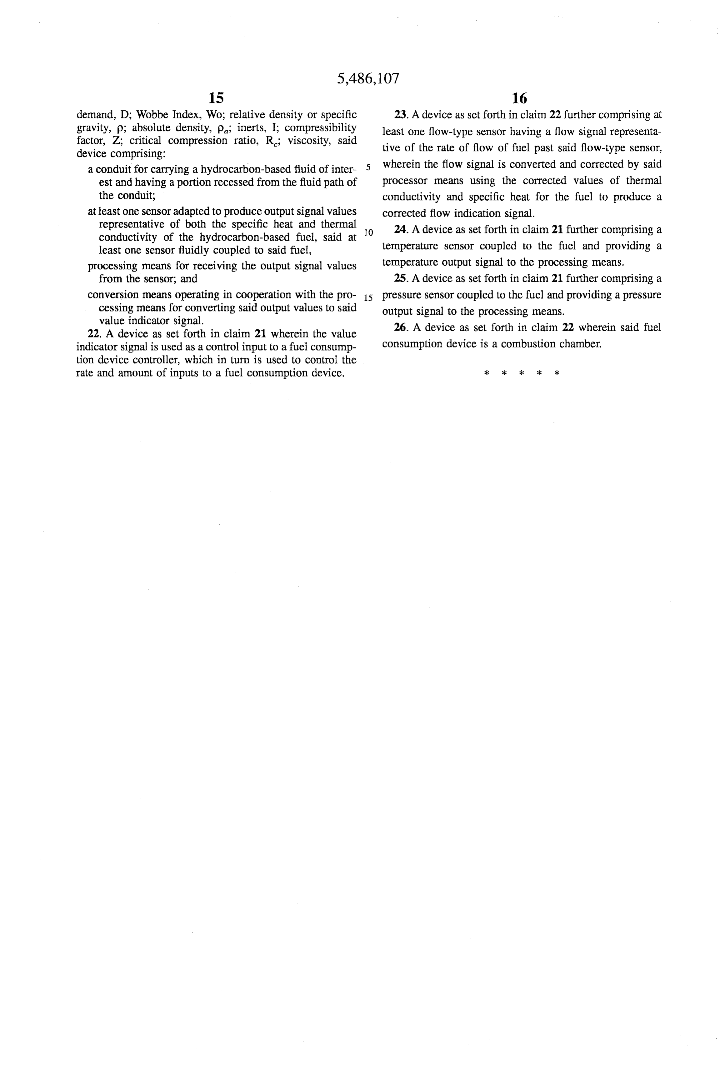
demand, D; Wobbe Index, Wo; relative density or specific 23. A device as set forth in claim 22 further comprising at gravity, p; absolute density, p, inerts, I; compressibility least one flow-type sensor having a flow signal representa factor, Z; critical compression ratio, R.; viscosity, said tive of the rate of flow of fuel past said flow-type sensor, device comprising:
a conduit for carrying a hydrocarbon-based fluid of inter wherein the flow signal is converted and corrected by said est and having a portion recessed from the fluid path of processor means using the corrected values of thermal the conduit; conductivity and specific heat for the fuel to produce a at least one sensor adapted to produce output signal values corrected flow indication signal. representative of both the specific heat and thermal 10 24. A device as set forth in claim 21 further comprising a conductivity of the hydrocarbon-based fuel, said at least one sensor fluidly coupled to said fuel, temperature sensor coupled to the fuel and providing a processing means for receiving the output signal values temperature output signal to the processing means. from the sensor, and 25. A device as set forth in claim 21 further comprising a conversion means operating in cooperation with the pro 15 pressure sensor coupled to the fuel and providing a pressure cessing means for converting said output values to said output signal to the processing means. value indicator signal. 26. A device as set forth in claim 22 wherein said fuel 22. A device as set forth in claim 21 wherein the value indicator signal is used as a control input to a fuel consump consumption device is a combustion chamber. tion device controller, which in turn is used to control the rate and amount of inputs to a fuel consumption device.
Page 16
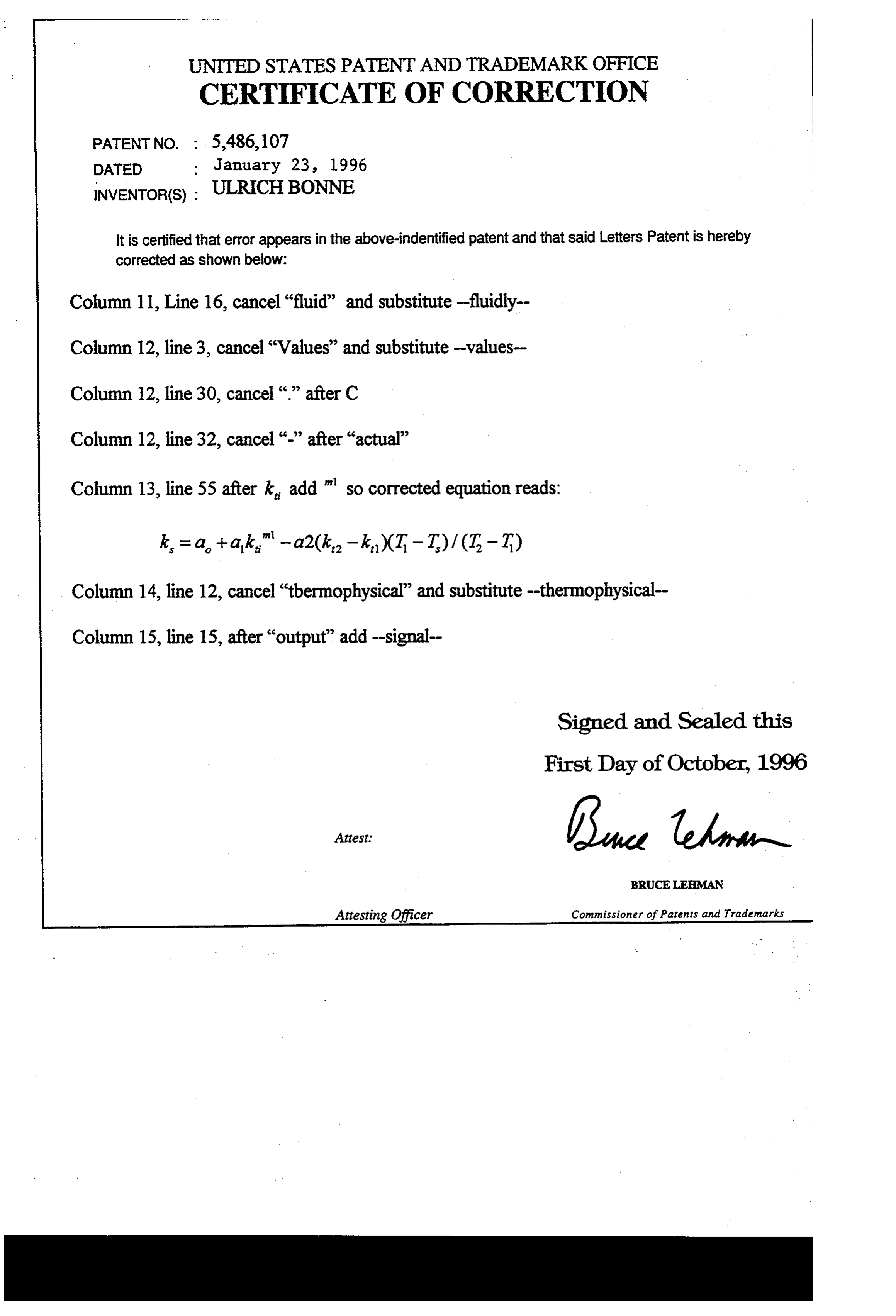
UNITED STATES PATENT AND TRADEMARK OFFICE
CERTIFICATE OF CORRECTION
INVENTOR(S): ULRCHBONNE
it is certified that error appears in the above-indentified patent and that said Letters Patent is hereby corrected as shown below:
Column 11, Line 16, cancel “fluid” and substitute-fluidly Column 12, line 3, cancel “Values” and substitute-values Column 12, line 30, cancel “..” after C
Column 12, line 32, cancel “-” after “actual”
Column 13, line 55 after k add "so corrected equation reads:
Column 14, line 12, cancel “tbermophysical” and substitute -thermophysical Column 15, line 15, after "output” add-signal
Signed and Sealed this
First Day of October, 1996
BRUCELEBMAN
Attesting Officer Commissioner of Patents and Trademarks
Provenance
- Collection
- Cited prior art
- Original PDF
- patentimages.storage.googleapis.com →
- Filed
- 1994-09-06
- Pages
- 16
- Method
- pdftotext (the PDF's own text layer) + pdftoppm 300dpi page scans
- Source
- Google Patents bibliographic record
- Granted
- 1996-01-23
- Inventors
- Ulrich Bonne; Honeywell Inc
- Transcribed from
- patentimages.storage.googleapis.com →