patent · US4372784
Method for heat treating pulverous raw material calcining combustor therefor
8 February 1983
Page 1 — bibliographic record
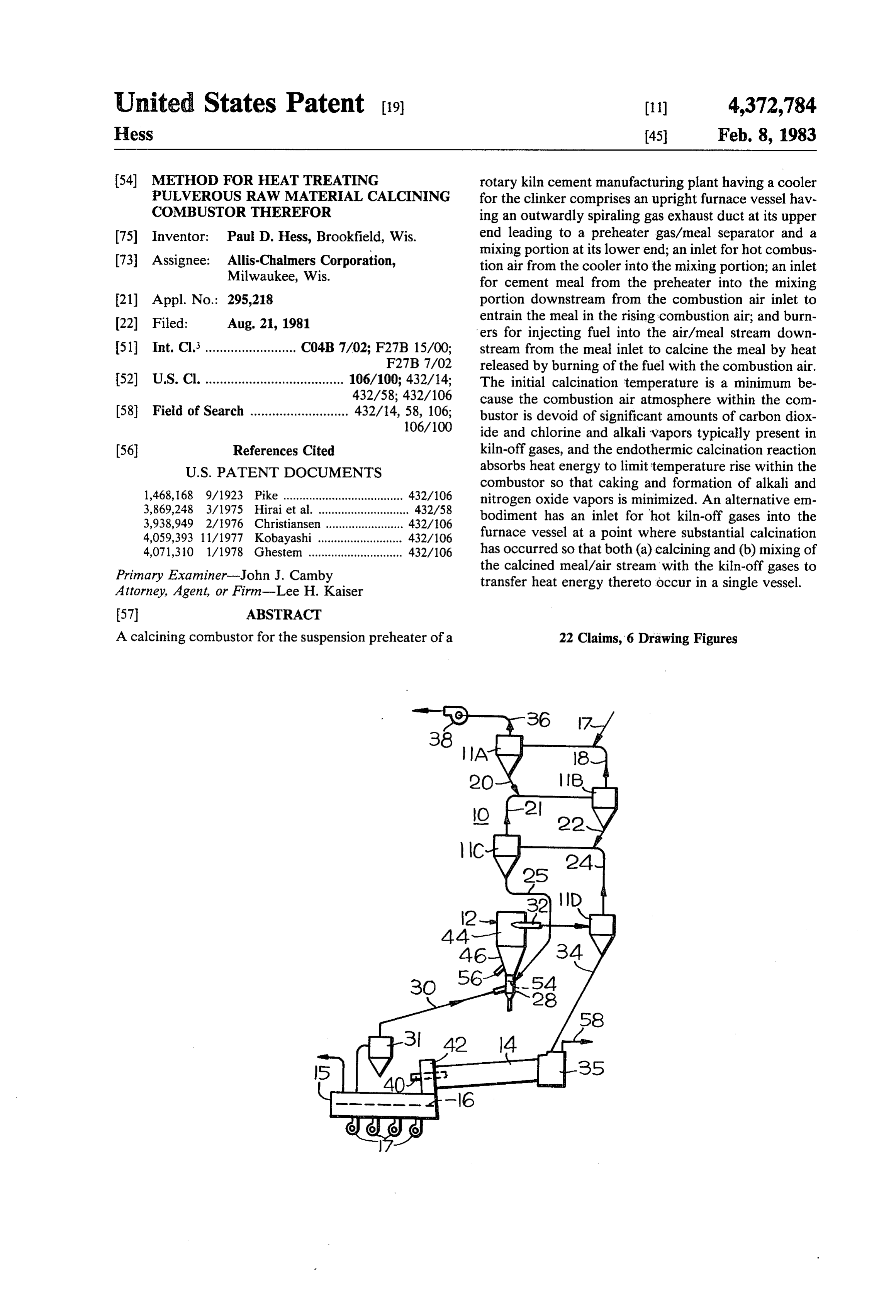
United States Patent (19) (11) 4,372,784 Hess 45 Feb. 8, 1983 54 METHOD FOR HEAT TREATING rotary kiln cement manufacturing plant having a cooler PULVEROUS RAW MATERAL CALCINING for the clinker comprises an upright furnace vessel hav COMBUSTOR THEREFOR ing an outwardly spiraling gas exhaust duct at its upper 75) Inventor: Paul D. Hess, Brookfield, Wis. end leading to a preheater gas/meal separator and a 73 Assignee: Allis-Chalmers Corporation, mixing portion at its lower end; an inlet for hot combus Milwaukee, Wis.
tion air from the cooler into the mixing portion; an inlet for cement meal from the preheater into the mixing 21 Appl. No.: 295,218 portion downstream from the combustion air inlet to (22 Filed: Aug. 21, 1981 entrain the meal in the rising combustion air; and burn ers for injecting fuel into the air/meal stream down 51) Int. Cl. ......................... C04B 7/02; F27B 15/00; stream from the meal inlet to calcine the meal by heat F27B 7/02 released by burning of the fuel with the combustion air.
52 U.S. Cl. ...................................... 106/100; 432/14; The initial calcination temperature is a minimum be 432/58; 432/106 cause the combustion air atmosphere within the com 58) Field of Search ........................... 432/14, 58, 106; bustor is devoid of significant amounts of carbon diox 106/100 ide and chlorine and alkali vapors typically present in (56) References Cited kiln-off gases, and the endothermic calcination reaction
combustor so that caking and formation of alkali and 1,468,168 9/1923 Pike ..................................... 432/106 nitrogen oxide vapors is minimized. An alternative em 3,869,248 3/1975 Hirai et al. ....... ... 432/58 bodiment has an inlet for hot kiln-off gases into the 3,938,949 2/1976 Christiansen .. ... 432/06 4,059,393 11/1977 Kobayashi ... 432/106 furnace vessel at a point where substantial calcination 4,071,310 1/1978 Ghestem ............................. 432/106 has occurred so that both (a) calcining and (b) mixing of Primary Examiner-John J. Camby the calcined meal/air stream with the kiln-off gases to Attorney, Agent, or Firm-Lee H. Kaiser transfer heat energy thereto occur in a single vessel.
A calcining combustor for the suspension preheater of a 22 Claims, 6 Drawing Figures
Page 2
Drawing sheet — no readable text.
Page 3
Drawing sheet — no readable text.
Page 4
METHOD FOR HEAT TREATING PULVEROUS
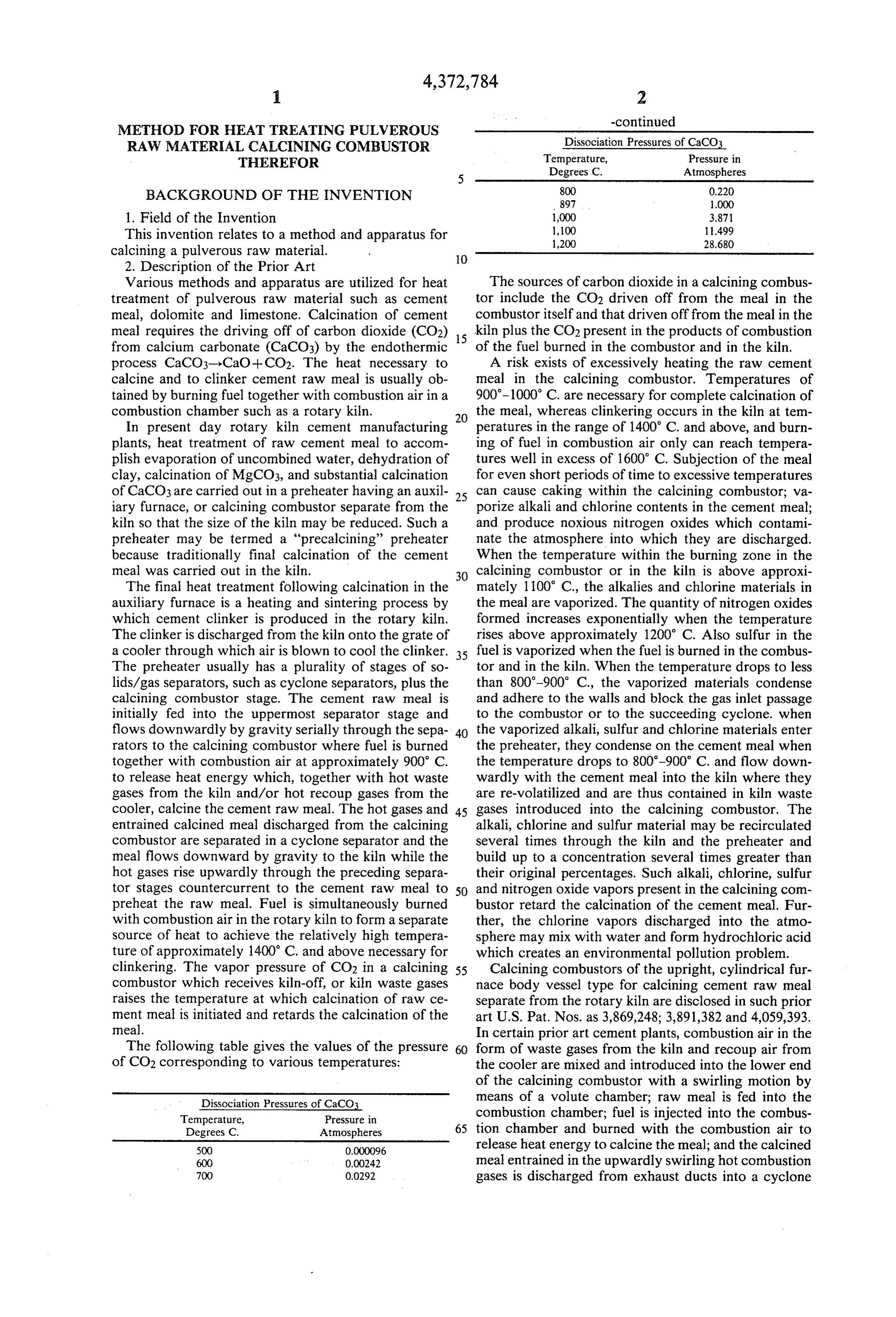
RAW MATERAL CALCNING COMBUSTOR Dissociation Pressures of CaCO3 THEREFOR Temperature, Pressure in Degrees C. Atmospheres
BACKGROUND OF THE INVENTION 800 0.220
1. Field of the Invention 1,000 3.871 This invention relates to a method and apparatus for 1,100 499
calcining a pulverous raw material. 10 2. Description of the Prior Art
Various methods and apparatus are utilized for heat The sources of carbon dioxide in a calcining combus treatment of pulverous raw material such as cement tor include the CO2 driven off from the meal in the meal, dolomite and limestone. Calcination of cement combustor itself and that driven off from the meal in the meal requires the driving off of carbon dioxide (CO2) 15 kiln plus the CO2 present in the products of combustion from calcium carbonate (CaCO3) by the endothermic of the fuel burned in the combustor and in the kiln. process CaCO3-)-CaO + CO2. The heat necessary to A risk exists of excessively heating the raw cement calcine and to clinker cement raw meal is usually ob meal in the calcining combustor. Temperatures of tained by burning fuel together with combustion air in a 900-1000 C. are necessary for complete calcination of combustion chamber such as a rotary kiln. the meal, whereas clinkering occurs in the kiln at tem In present day rotary kiln cement manufacturing 20 peratures in the range of 1400° C. and above, and burn plants, heat treatment of raw cement meal to accom ing of fuel in combustion air only can reach tempera plish evaporation of uncombined water, dehydration of tures well in excess of 1600° C. Subjection of the meal clay, calcination of MgCO3, and substantial calcination for even short periods of time to excessive temperatures of CaCO3 are carried out in a preheater having an auxil 25 can cause caking within the calcining combustor; va iary furnace, or calcining combustor separate from the porize alkali and chlorine contents in the cement meal; kiln so that the size of the kiln may be reduced. Such a and produce noxious nitrogen oxides which contami preheater may be termed a "precalcining' preheater nate the atmosphere into which they are discharged. because traditionally final calcination of the cement When the temperature within the burning zone in the meal was carried out in the kiln. 30 calcining combustor or in the kiln is above approxi The final heat treatment following calcination in the mately 100 C., the alkalies and chlorine materials in auxiliary furnace is a heating and sintering process by the meal are vaporized. The quantity of nitrogen oxides which cement clinker is produced in the rotary kiln. formed increases exponentially when the temperature The clinker is discharged from the kiln onto the grate of rises above approximately 1200° C. Also sulfur in the a cooler through which air is blown to cool the clinker. 35 fuel is vaporized when the fuel is burned in the combus The preheater usually has a plurality of stages of so tor and in the kiln. When the temperature drops to less lids/gas separators, such as cyclone separators, plus the than 800-900 C., the vaporized materials condense calcining combustor stage. The cement raw meal is and adhere to the walls and block the gas inlet passage initially fed into the uppermost separator stage and to the combustor or to the succeeding cyclone. when flows downwardly by gravity serially through the sepa 40 the vaporized alkali, sulfur and chlorine materials enter rators to the calcining combustor where fuel is burned the preheater, they condense on the cement meal when together with combustion air at approximately 900 C. the temperature drops to 800-900° C. and flow down to release heat energy which, together with hot waste wardly with the cement meal into the kiln where they gases from the kiln and/or hot recoup gases from the are re-volatilized and are thus contained in kiln waste cooler, calcine the cement raw meal. The hot gases and 45 gases introduced into the calcining combustor. The entrained calcined meal discharged from the calcining alkali, chlorine and sulfur material may be recirculated combustor are separated in a cyclone separator and the several times through the kiln and the preheater and meal flows downward by gravity to the kiln while the build up to a concentration several times greater than hot gases rise upwardly through the preceding separa their original percentages. Such alkali, chlorine, sulfur tor stages countercurrent to the cement raw meal to 50 and nitrogen oxide vapors present in the calcining com preheat the raw meal. Fuel is simultaneously burned bustor retard the calcination of the cement meal. Fur with combustion air in the rotary kiln to form a separate ther, the chlorine vapors discharged into the atmo Source of heat to achieve the relatively high tempera sphere may mix with water and form hydrochloric acid ture of approximately 1400° C. and above necessary for which creates an environmental pollution problem. clinkering. The vapor pressure of CO2 in a calcining 55 Calcining combustors of the upright, cylindrical fur combustor which receives kiln-off, or kiln waste gases nace body vessel type for calcining cement raw meal raises the temperature at which calcination of raw ce separate from the rotary kiln are disclosed in such prior ment meal is initiated and retards the calcination of the art U.S. Pat. Nos. as 3,869,248; 3,891,382 and 4,059,393. meal. In certain prior art cement plants, combustion air in the The following table gives the values of the pressure 60 form of waste gases from the kiln and recoup air from of CO2 corresponding to various temperatures: the cooler are mixed and introduced into the lower end of the calcining combustor with a swirling motion by
Dissociation Pressures of CaCO3 means of a volute chamber; raw meal is fed into the Temperature, Pressure in combustion chamber; fuel is injected into the combus Degrees C. Atmospheres 65 tion chamber and burned with the combustion air to 500 0.000096 release heat energy to calcine the meal; and the calcined 600 0.00242 meal entrained in the upwardly swirling hot combustion 700 0.0292 gases is discharged from exhaust ducts into a cyclone
Page 5
separator of the preheater. In certain such prior art An alternative embodiment of my calcining combus calcining combustors fuel is injected into combustion tor accomplishes calcination of the cement meal and gases mixed with air and burns to release heat energy at subsequent mixing of the calcined meal/air stream with a point upstream from the meal feed inlet, and such hot kiln-off gases in a single vessel to thereby capture burning of combustion air and fuel within the calcining 5 heat energy from the kiln-off gases for preheating the combustor can reach temperatures in excess of 1600 C. raw cement meal in the suspension preheater. In such and form an extremely high temperature zone which embodiment the furnace vessel has an inlet for hot kiln may excessively heat the meal; cause caking within the off gases downstream from the fuel burners and at a combustor; vaporize the alkali and chlorine contents of point where substantial calcination of the cement meal the meal; form noxious nitrogen oxides, and require use 10 has occurred so that the kiln-off gases mix with the of inordinate thickness of refractory material in the calcined meal/air stream within the same vessel and the walls of the calcining furnace. In other prior art calcin resulting mixture is discharged through the gas exhaust ing combustors combustion air from the cooler is mixed duct into the lowermost separator stage of the pre with the kiln-off waste gases in the calcining furnace, or heater. Inasmuch as kiln-off gases are not utilized as a before entering the furnace, and the presence of this gas 15 source of combustion air, the lower end of the calcining impedes and delays the combustion process. Also the combustor vessel can be disposed below the fuel firing waste kiln-off gases will contain a high level of CO2 level in the kiln, thereby permitting the height of the driven off from the meal in the kiln and from coal fired suspension preheater tower to be reduced significantly. in the kiln which will raise the initial calcining tempera The method of my invention for heat treating cement ture of CaCO3 as much as 200° C. The kiln-off gases 20 raw meal in an upright calcining combustion vessel of a contain volatile chlorine and alkali vapors that may be rotary kiln cement plant comprises feeding hot combus condensed and form coatings on the pulverized parti tion air from the cooler into the lower end of the vessel cles that further inhibit calcination and will also coat the and simultaneously withdrawing the air from adjacent calcinator walls adjacent its gas inlet passage, all of the top of the vessel to create upward flow of combus which are undesirable. 25 tion air within the vessel; directing preheated cement SUMMARY OF THE INVENTION meal into the rising combustion air within the vessel at a point downstream from the combustion air inlet so
A calcining combustor for pulverous raw material in that the meal is entrained in the combustion air stream; accordance with the invention comprises an upright and injecting fuel into the air/meal stream within the furnace vessel having a mixing portion at its lower end; 30 vessel downstream from the entrance of meal and burn an inlet for combustion air into the mixing portion; ing the fuel with the combustion air to release heat means including a gas exhaust duct adjacent the top energy to calcine the meal, whereby the endothermic wall of the vessel for causing the combustion air to flow reaction of calcining the cement meal limits the temper upwardly in the vessel from the air inlet to the exhaust ature rise within the vessel. An alternative method in duct; an inlet for pulverous raw material into the mixing 35 cludes introducing hot waste gases from the kiln into portion downstream in the direction of air flow from the vessel at a point downstream from injection of the the combustion air inlet; whereby the raw material is fuel and where substantial calcination has occurred to entrained in the rising combustion air; and means for thereby mix the waste gases with, and transfer the heat injecting fuel into the combustion air/material stream energy thereof to, the calcined meal/gas stream within within said vessel downstream from the meal inlet and 40 the vessel.
for burning the fuel with the combustion air to thereby BRIEF DESCRIPTION OF THE DRAWINGS release heat energy to calcine the pulverous raw mate rial in an endothermic reaction that limits temperature The objects and advantages of the invention will be rise within the furnace vessel. more readily apparent from consideration of the at When the calcining combustor of the invention is 45 tached drawing wherein:
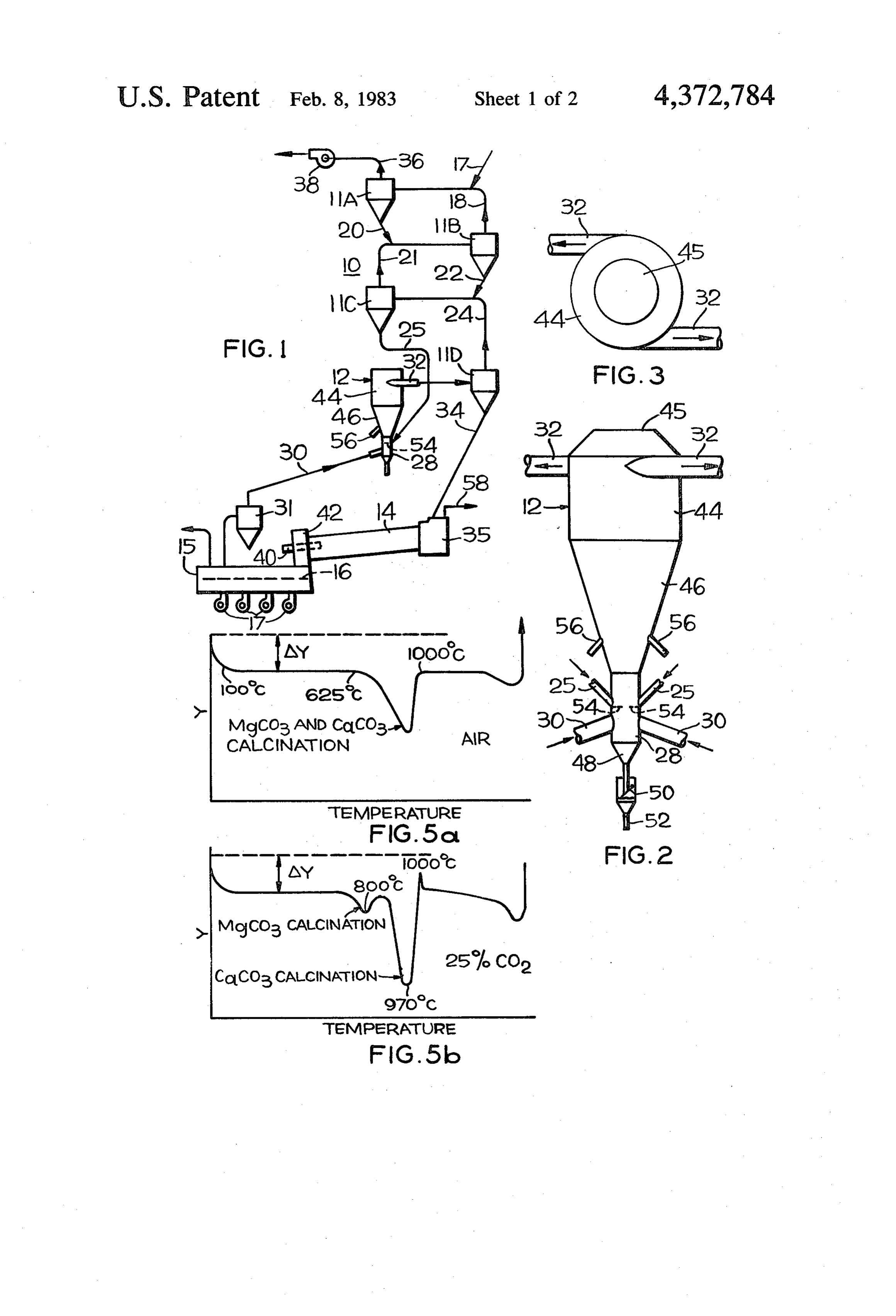
utilized in the suspension preheater of a rotary kiln FIG. is a schematic representation of a rotary kiln cement manufacturing plant having a cooler for cement cement manufacturing plant embodying the calcining clinker, hot recoup air from the cooler is fed to the combustor of the invention;
combustion air inlet; preheated cement meal from the FIG. 2 is a front view of the calcining combustor second lowermost cyclone separator stage of the pre- 50 shown in FIG. 1;
heater is fed to the raw material inlet; and the gas ex FIG. 3 is a top view of the combustor shown in FIG. haust duct discharges the calcined meal/air stream in a 2;
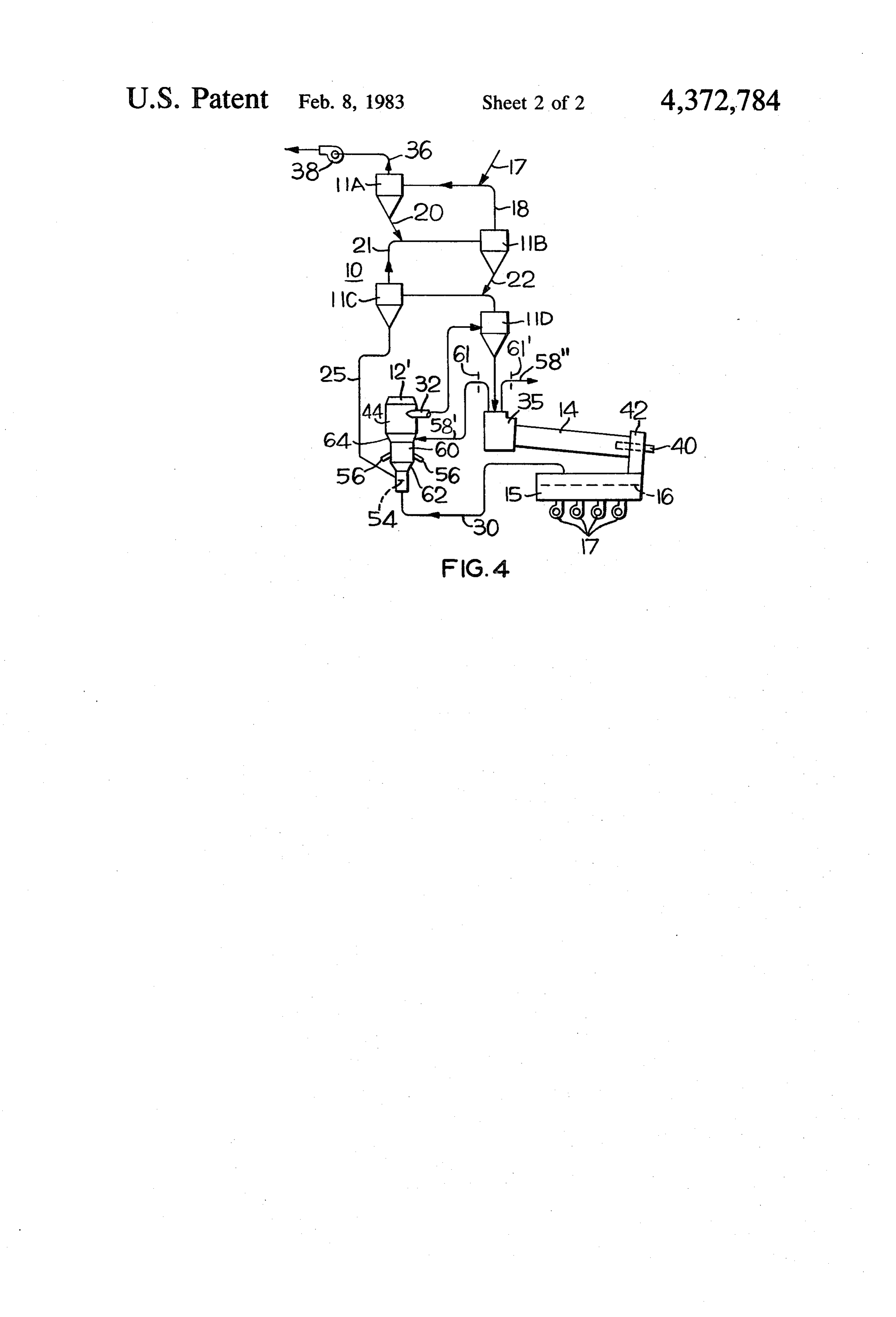
spirally outward direction through the gas exhaust duct FIG. 4 is a schematic representation of an alternative into the lowermost separator stage of the preheater embodiment of the invention wherein cement meal is which separates the meal from the hot gases and dis- 55 calcined and the calcined meal/air stream is mixed with charges the calcined meal into the rotary kiln while the hot kiln-off gases in a single vessel to recover waste gas hot gases flow upwardly serially through the preheater heat in the preheater and to control the recirculation separator stages in countercurrent relation to the ce levels of sulfur, alkali and chlorine; and ment meal descending by gravity to thereby preheat the FIGS. 5a and 5b are thermal diagrams of cement raw meal. The initial calcination temperature is minimum 60 meal versus temperature for respectively; (a) a combus because the combustion air is devoid of significant tion air atmosphere and (b) a combustion air atmosphere amounts of carbon dioxide and chlorine and alkali va containing 25% carbon dioxide. pors typically present in kiln-off gases, and the endo DESCRIPTION OF THE PREFERRED thermic calcination reaction absorbs heat energy re EMBODIMENTS leased by burning of the fuel with the combustion air to 65 thereby limit the temperature rise within the vessel so FIG. schematically illustrates a rotary kiln cement that caking and formation of alkali, chlorine and nitro manufacturing plant having a suspension preheater 10 gen oxide vapors is minimized. which includes four stages of vertically spaced apart
Page 6
separators 11A, 11B, 11C and 11D which may be of the Such cooler combustion air may be at approximately cyclone type or of the helical duct type disclosed in my 700° C. to 1000' C. and will not contain the carbon copending application Ser. No. 222,034 filed Jan. 2, dioxide and alkali, chlorine and sulfur vapors and nox 1980, now U.S. Pat. No. 4,381,692, serially connected ious nitrogen oxides which are formed in kiln 14 and are with an auxiliary furnace, or calcining combustor 12 typically present in waste gases from a kiln. The meal embodying my invention, an inclined rotary kiln 14, and charged from separator 11C into mixing pipe portion 28 a clinker cooler 15. An initial feed inlet 17 for raw ce is preheated in separator stages 11A, 11B and 11C to ment meal is provided in the gas outlet duct 18 from approximately 700-800° C. before it is introduced into cyclone separator 11B, which duct is also the inlet for combustor 12 and is preferably directed downward cyclone separator 11A, and the raw meal is entrained in 10 through meal inlet duct 25 against splash plates 54 at a the hot gases rising within duct 18 so that heat energy in point downstream in the direction of gas flow from the the hot gases is transferred to the meal. The meal sepa combustion air inlet 30 so that the preheated meal is rated from the gases in separator 11A flows downward dispersed and entrained and carried with the rising by gravity through a meal discharge duct 20 from sepa combustion air.
rator 11A which registers with the gas outlet duct 21 15 As best shown in FIG. 2, calcining combustor 12 from separator 11C, which duct also is the inlet for preferably comprises an upright furnace body vessel separator 11B, so that the meal from 11A is entrained in having an elongated cylindrical upper portion 44 with the hot gases from 11C. The meal discharged from its axis vertical; a closed top 45; diametrically opposed separator 11B flows downward by gravity through a spirally outward, or tangentially directed gas exhaust meal discharge duct 22 which registers with the gas 20 ducts 32 from upper portion 44 adjacent closed top 45; outlet duct 24 from lowermost separator 11D which an inverted frustoconical intermediate portion 46 dis duct also forms the inlet for separator 11C. Preheated posed below upper portion 44 and formed by an in cement meal discharged from separator 11C flows wardly inclined annular wall; tubular mixing pipe por downward by gravity through a meal feed duct 25 into tion 28 disposed below and registering with the open the mixing pipe portion 28 of calcining combustor 12 25 smaller diameter end of frustoconical intermediate por wherein, as described hereinafter, the preheated meal is tion 46; a frustoconical dropout box 48 disposed below entrained in hot combustion air, or recoup air, from mixing pipe 28; a meal valve 50 which normally closes cooler 15 introduced into mixing pipe portion 28 dropout box 48; and a meal drain pipe 52 disposed through a combustion air duct 30 which is positioned below dropout box 48.
upstream in the direction of combustion air flow from 30 The preheated meal is introduced directly into mix meal feed duct 25 and may include a dust collector 31 ing pipe 28 through meal feed duct 25 which is directed for removal of clinker dust from the hot combustion air. downward toward splash plate 54 disposed within mix The preheated combustion air is drawn upwardly ing pipe 28 which disperses the preheated meal into the through vessel 12, preferably with an outwardly swirl hot combustion air that rises rapidly within mixing pipe ing motion, by an induced draft fan 38. The meal is 35 28 and carries the meal into frustoconical lower portion suspended in the rising combustion air within mixing 46. Such entrainment of meal in rising hot gases is more pipe 28 and is calcined in frustoconical intermediate efficient than prior art calciners which introduce the portion 46 and enlarged diameter cylindrical upper preheated meal into the combustion gas duct with the portion 44 by heat energy released by burning fuel, undesirable result that a significant amount of the meal injected into the gas/meal stream at a point downstream 40 falls into the dropout box of such prior art calciners. from meal duct 25, with the hot combustion air. The hot Substantially complete calcining of the preheated raw gases flow with an upwardly swirling motion through meal is accomplished within frustoconical intermediate combustor 12, and the gases with calcined meal therein portion 46 and cylindrical upper portion 44 by heat are discharged from combustor 12 through a spirally energy released by burning of fuel injected by burners outward, or tangentially directed exhaust gas duct 32 45 56 into the air-meal stream at a point upstream from into the inlet for the lowermost cyclone separator 11D. meal inlet 25 for combustion and release of heat which The calcined meal separated in 11D flows downward is transferred directly to the suspended meal for heat by gravity through a duct 34 and is charged into a kiln exchange and calcining. The relatively small diameter inlet chamber 35, while the hot gases from separator of mixing pipe 28 assures entrainment of the meal in the 11D are drawn upwardly by induced draft fan 38 and 50 combustion air, and the velocity of the air/meal stream flow upward through gas outlet duct 24 and separator decreases as it flows upwardly and outwardly in the stages 11C, 11B, and 11A sequentially in countercurrent relatively larger diameter intermediate portion 46 to flow to the descending raw meal and are finally dis assure longer residence time for calcination of the meal. charged from separator 11A through an exhaust duct Kiln-off gases fed into calcining combustors of prior 36. 55 art rotary kiln cement manufacturing plants typically The calcined meal from separator 11D is charged into contained a high percentage of carbon dioxide as a rotary kiln 14 through duct 34 and kiln inlet chamber 35 result of calcination of raw meal and from burning of and is further heated and clinkered by heat released coal as a fuel and also contained significant percentages from combustion of fuel injected into kiln 14 through a of chlorine, sulfur, alkali and nitrogen oxide vapors burner 40 provided on a kiln hood 42. The burnt clinker 60 caused by volatilization of such materials in the cement formed in kiln 14 is discharged onto a grate 16 in a meal at high temperatures. The relatively high carbon cooler 15 and cooled by air blown by fans 17 through dioxide pressure and the presence of the alkali, chlorine, cooler 15. The waste hot gases from kiln 14 may be sulfur and nitrogen oxide vapors in the kiln-off gases exhausted from inlet chamber 34 through a 100% by retarded the calcination of cement meal in the calcining pass duct 58. 65 combustor of such prior art plants and raised the initial The hot recoup air from cooler 15 is introduced into calcination temperature as much as 200° C. FIGS. 5a the lowermost portion of tubular mixing pipe portion 28 and 5b are thermal diagrams of cement meal versus of combustor 12 and rises through the mixing pipe 28. temperature for a combustion air atmosphere and for an
Page 7
atmosphere containing 25% CO2. In these diagrams Ay will be appreciated that the disclosed method of inject represents specific heat. It will be noted from FIG. 5a ing fuel into the hot air stream having preheated meal that the endothermic reaction of calcination of cement suspended therein is the ideal method of transferring meal in the combustion air atmosphere is initiated at heat by burning of fuel with the combustion air to the approximately 625 C., whereas FIG. 5b illustrates that meal particles because the highest thermal efficiency the endothermic calcination of the MgCo3 in the cement may be attained thereby.
meal in the 25% CO2 atmosphere is initiated at a tem Since kiln-off gases are not introduced into calcining perature above 625 C. and that calcination of CaCO3 in combustor 12, the lower end of calcining combustor 12 the cement meal is initiated at a temperature above can be at a height below burner 40 of kiln 14, thereby approximately 800° C. O permitting a substantial reduction in the height of sus A plurality of burners 56 may be disposed on the pension preheater 10 (although this is not illustrated in annular wall of frustoconical intermediate portion 46 at FIG. 1).
a point downstream in the direction of gas flow from Although FIG. 1 discloses only a single cooler re meal inlet duct 25. Burning of the fuel with the combus coup air duct 30 to combustor 12, a single preheated tion air in the absence of CO2 and other gases typically 15 meal feed duct 25 to mixing pipe 28, a single burner 56 present in kiln-off gas releases heat energy which cal and a single exhaust duct 32 from upper portion 44, it cines the preheated meal suspended in the combustion will be appreciated that a plurality of such members air in an endothermic process having minimum calcina may be provided as shown in FIG. 2.
tion initiation temperature. The meal entrained in the Dropout box 48, meal valve 50 and meal pipe 52 are combustion air absorbs heat energy and prevents exces provided to prevent buildup of cement meal at the bot sive heat rise within combustor 12 and forms a uniform tom of mixing pipe portion 28 in the event of unbal temperature zone in the range of 800-1000° C. required anced air/meal flow condition such as might occur for controlled calcination within combustor 12. The during shutdown. The elevation of dropout box 48 can degree of calcination is selectively controlled by regu be below kiln 14 as the material falling through is mini lating the amount of fuel burned in combustor 12. No 25 mal, thereby permitting reduced preheater tower height excessively high temperature zone is formed within and permitting combustor 12 and the fuel supply equip combustor 12 as sometimes occurs in prior art calcining ment to be closer to ground level. furnaces when density of meal feed is low adjacent to FIG. 1 shows a rotary kiln cement plant wherein the burner flame and temperatures can exceed 1600° C. 100% of the kiln waste gases is bypassed because of Consequently caking is minimized within combustor 12, high levels of sulfur, alkali, chlorine and/or nitrogen formation of nitrogen oxides and alkali, sulfur and chlo oxides in the kiln-off gas. FIG. 4 represents an alterna rine vapors is prevented in the calcining zone, and use tive embodiment of the invention wherein calcination of of exceptionally thick refractory insulating material in cement meal and subsequent mixing of calcined meal the walls of combustor furnace 2 is obviated. The fuel /air stream with controlled amounts of kiln-off gases is burns rapidly in oxygen-rich air and immediately and 35 accomplished in a single vessel to recover heat energy directly transfers the heat released to the entrained from the kiln-off gas in the preheater and to control the pulverized material. recirculation levels of alkali and chlorine. Frustoconical intermediate portion 46 expands up A controlled portion of hot kiln waste gases is dis wardly and merges into enlarged cylindrical upper por charged from chamber 35 into a kiln-off gas feed duct tion 44 having opposed, outwardly spiraling, or tangen 40 58 which registers with combustor furnace vessel 12' tially directed exhaust ducts 32 adjacent top wall 45 that downstream from fuel burners 56 at a point where sub cause upwardly and outwardly whorling motion of the stantially complete calcination of the cement meal has air/meal stream within combustor 12. The swirling air occurred. A selected portion of the kiln-off gases may expands substantially before leaving exhaust ducts 32 as be diverted to a bypass duct 58". The percentage of the fuel injected into the gas/meal stream burns with 45 kiln-off gases flowing in feed duct 58' and in bypass duct the combustion air having meal suspended therein to 58' respectively may be controlled by dampers therein release heat energy and calcine the meal. Such upward schematically represented at 61' and 61". Calcining and outward motion of the air/meal stream results in a combustor 12 has an inverted frustoconical portion 62 lower velocity, longer residence time flow conditions of positioned above tubular mixing pipe portion 28 and the gas/meal stream within inverted frustoconical inter which registers with a cylindrical intermediate portion mediate portion 46 and enlarged diameter cylindrical 60. A plurality of burners 56 are provided on the walls portion 44 to thereby assure complete fuel combustion, of intermediate portion 60 downstream from meal inlet heat transfer and pyro-process reactions within combus duct 25 so that the fuel is combusted with recoup cooler tor 12. The relatively low velocity of the air/meal air within intermediate portion 60 to permit substan stream within upper cylindrical portion 44 may cause 55 tially complete calcination of preheated cement meal some of the meal to settle along the side walls and fall entrained in the recoup cooler air to be carried out in into the inverted frustoconical portion 46 where the cylindrical intermediate portion 60. meal is again suspended in the upwardly flowing air Combustor 12' also has an inverted frustoconical stream and recirculated. The combined whorling and portion 64 disposed above intermediate portion 60 and recirculating flow of the air/meal stream increases resi 60 which registers at its lower end with intermediate por dence time within the larger diameter cyclindrical tion 60 and at its upper end with upper portion 44. upper portion 44 to assure complete burning of the fuel Kiln-off gas feed duct 58' registers with frustoconical and effectively reduces the height of combustor 12 in portion 64 so that kiln waste gases, which may be at comparison to a straight high velocity pipe for equiva approximately 1000 C., are introduced into upper por lent combustion time. The temperature rise of the air 65 tion 44 above burners 56 to mix with and transfer heat stream is controlled by the endothermic calcining pro to the calcined meal/air stream before the resulting cess so that the temperature of the gases discharged mixture is exhausted through ducts 32 to separator 11D from exhaust ducts 32 is approximately 800-900° C. It for preheating of the descending cement meal. Combus
Page 8
tion air duct 30 directs hot recoup air from clinker decreases to provide longer residence time as it flows cooler 15 in an axial direction into the bottom end of through said intermediate portion, and fuel burner mixing pipe portion 28 so that it rises and is drawn means for injecting fuel into the combustion air/- upward therein by induced draft fan 38. Preheated meal material stream within said intermediate portion at a feed duct 25 directs preheated meal from separator 11C point downstream from said material inlet and for burn against a splash plate 54 disposed within mixing pipe 28 ing said fuel with said combustion air, whereby said to disperse the preheated meal into the rising combus pulverous raw material is calcined by heat released by tion air from cooler 15 at a point downstream from the burning of said fuel with combustion air in an endother combustion air inlet 30 and upstream from burners 56. mic reaction that limits temperature rise within said The relatively small diameter of mixing pipe portion 28 10 vessel.
assures entrainment of the preheated meal in the rising 2. A calcining combustor in accordance with claim 1 recoup air, while the larger diameter intermediate por wherein said mixing portion is cylindrical and said com tion 60 slows the velocity of the recoup meal/air stream bustion air inlet communicates with the lower end of and provides greater time for calcination of the meal said mixing portion.
within intermediate portion 60. Burning of the fuel with 15 3. A calcining combustor in accordance with claim 1 the recoup air in the absence of CO2 and other gases wherein said upper portion has diametrically opposed typically present in kiln-off gases releases heat energy outwardly spiraling gas exhaust ducts adjacent said for calcining of the cement meal in an endothermic closed top which create upwardly swirling flow of said process having minimum calcination initiation tempera combustion air/material stream within said interior ture. The meal entrained in the recoup air absorbs heat 20 portion.
energy and prevents excessive heat rise within interme 4. A calcining combustor in accordance with claim 5 diate portion 60 and forms a uniform temperature zone wherein said intermediate portion is of inverted frusto in the range of 800-1000 C. required for controlled conical configuration and communicates at its opposite calcination within combustion vessel 12'. No exces ends with said mixing portion and with said upper por sively high temperature zone is formed within interme 25 tion.
diate portion 60 and consequently caking is minimized 5. A calcining combustor in accordance with any one and formation of alkali, chlorine, sulfur and nitrogen of claims 1, 2, 3, or 4 wherein said means for causing oxide vapors is minimized. The hot kiln-off gases can be said combustion air to flow upwardly through said introduced in controlled amounts into vessel 12 through vessel includes an induced draft fan connected to said duct 58' after substantially complete calcination of the 30 gas exhaust duct.
cement meal to add the heat energy of the kiln-off gases 6. A calcining combustor in accordance with any one to the calcined meal/air stream so the heat energy is of claims 1, 2, 3 or 4 for a rotary kiln cement plant and available to preheat the cement meal in the preheater. including an inlet into said furnace vessel for waste FIG. 4 represents that mixing portion 28 and interme gases from the kiln located downstream from said fuel diate portion 60 of combustor vessel 12' are below the 35 injecting means at a point above said intermediate por level of burner 40 which injects fuel into kiln 14, tion and where substantially complete calcination of thereby permitting reduction in height of the preheater said material has occurred to permit mixing and transfer tower. It will be appreciated that the recirculation lev of heat energy from said waste gases to the calcined els of alkali and chlorine will be relatively low in calcin material/air stream without retardation of calcination ing combustor 12' because the alkali and chlorine va 40 which would be caused by the carbon dioxide in said pors formed in kiln 14 are not recirculated through the waste gases.
intermediate portion 60 of combustor 12 in which sub 7. A calcining combustor in accordance with claim 6 stantially complete calcination of the cement meal oc having damper means for selectively controlling the CS. amount of waste gases introduced through said kiln The embodiments of the invention in which an exclu 45 waste gas inlet into said furnace vessel. sive property or privilege is claimed are defined as 8. A calcining combustor in accordance with any one follows: of claims 1, 2, 3, or 4 for the suspension preheater of a 1. A calcining combustor for raw pulverous material rotary kiln cement manufacturing plant having a cooler comprising, in combination, an upright furnace vessel for clinker from the kiln and serially connected solids/- having a cylindrical upper portion with its axis vertical 50 gas separators at varying heights, wherein said combus and a closed top and a mixing portion adjacent its lower tion air inlet is connected by a duct to said cooler, said end and an intermediate portion between said upper and raw material inlet is connected by a duct to the meal mixing portions of smaller diameter than said upper discharge opening of a separator of said preheater, and portion, an inlet for combustion air into said mixing said gas discharge duct is connected to the inlet of the portion, means including a tangentially directed gas 55 lowermost separator of said preheater. exhaust duct spiraling outwardly from said upper por 9. A calcining combustor for a cement manufacturing tion adjacent said closed top for causing said combus plant having a rotary kiln and a cooler for clinker from tion air introduced through said inlet to flow with up said kiln comprising an upright furnace vessel having a wardly swirling motion through said intermediate por cylindrical upper portion with its axis vertical and a tion of said vessel toward said gas exhaust duct, an inlet 60 closed top and a mixing portion at its lower end, an inlet for said raw pulverous material into said mixing portion for heated combustion air from said cooler into said downstream in the direction of air flow from said com mixing portion, said furnace vessel also having an inter bustion air inlet, whereby said pulverous material falls mediate portion between said upper and mixing por into and is entrained in said rising combustion air, said tions of smaller diameter than said upper portion and mixing portion being of smaller diameter than said inter 65 means including a tangentially directed gas exhaust duct mediate portion to assure that said raw pulverous mate spiraling outwardly from said upper portion for causing rial is entrained in said upwardly rising combustion air said combustion air to flow with upwardly swirling and that the velocity of the combustion air/meal stream motion through said intermediate portion toward said
Page 9
gas exhaust duct, an inlet for cement meal into said 13. A calcining combustor in accordance with claim mixing portion downstream from said combustion air 10 wherein said intermediate portion is of inverted frus inlet, whereby cement meal falls into and is entrained in toconical configuration.
combustion air rising upwardly from said combustion 14. A calcining combustor in accordance with claim air inlet toward said gas exhaust duct, fuel burner means 10 wherein said means for causing said combustion air for injecting fuel into the combustion air/meal stream to flow upwardly through said vessel includes an in within said intermediate portion at a point downstream duced draft fan connected to said gas exhaust ducts. from said meal inlet and for burning said fuel with said 15. A calcining combustor for the suspension pre combustion air, whereby said meal is calcined by heat 10 heater of a cement manufacturing plant having a rotary released by burning of said fuel with said combustion air kiln, a cooler for clinker discharged from said kiln, and in an endothermic reaction within said intermediate a plurality of meal/gas separators at varying heights portion that limits temperature rise within said vessel, serially connected with said combustor and said kiln so and an inlet into said furnace vessel for hot waste gases that meal is discharged from the lowermost separator from said kiln at a point downstream from said fuel 15 into said kiln and gas exhausted therefrom rises serially injecting means and above said intermediate portion through the remaining separators to preheat cement where substantially complete calcination of said cement meal descending therethrough by gravity comprising, meal has occurred, whereby calcining of cement meal in combination, an upright furnace body vessel having a in a combustion air atmosphere and mixing the calcined cylindrical upper portion with its axis vertical and a meal/air stream with kiln-off gases occur in the same 20 closed top and a mixing portion adjacent its lower end, vessel without retardation of calcination which would a combustion air inlet into said mixing portion con otherwise be caused by the carbon dioxide in said kiln nected by a duct to said cooler, diametrically opposed, Waste gases. tangentially directed gas exhaust ducts spiraling out 10. A calcining combustor for the preheater of a wardly from said upper portion adjacent said closed top cement manufacturing plant having a rotary kiln and a 25 and connected to the inlet to said lowermost separator, cooler for clinker from said kiln comprising, in combi a fan for causing combustion air introduced into said nation, an upright furnace vessel having a cylindrical mixing portion through said inlet to rise within said upper portion with its axis vertical and a closed top and vessel and flow upward serially through said separators, a mixing portion adjacent its lower end, an inlet for a cement meal inlet into said mixing portion connected heated combustion air from said cooler into said mixing 30 by a duct to the meal outlet of the lowermost separator portion, means including diametrically opposed, tan and positioned downstream in the direction of air flow gentially directed gas exhaust ducts spiraling outwardly from said combustion air inlet, whereby cement meal from said upper portion adjacent said closed top for falls into and is entrained in the rising heated combus causing said heated combustion air introduced through tion air within said vessel, said furnace body vessel also said inlet to flow with upwardly swirling motion 35 having an intermediate portion between said upper and through said vessel toward such gas exhaust duct, an mixing portions of larger diameter than said mixing inlet for cement meal into said mixing portion down portion to decrease the velocity of the air/meal stream stream in the direction of air flow from said combustion and provide a longer residence time within said inter air inlet, whereby said meal falls into and is entrained in mediate portion, and means protruding through a wall said rising heated combustion air, said vessel having an 40 of said intermediate portion for injecting fuel into the intermediate portion between said upper and mixing combustion air/meal stream within said vessel at a point portions of larger diameter than said mixing portion to downstream from said meal inlet and for burning said decrease the velocity of the air/meal stream and pro fuel with said combustion air, whereby said meal is vide longer residence time for calcination of meal calcined by heat released by burning of said fuel with within said intermediate portion, and means for inject 45 said combustion air in an endothermic reaction that ing fuel into the combustion air/meal stream within said limits the temperature rise within said vessel. intermediate portion at a point downstream from said 6. A calcining combustor in accordance with claim meal inlet and for burning said fuel with said combus 15 and including a kiln waste gas inlet into said furnace tion air, whereby said meal is calcined by heat released body vessel at a point downstream from said fuel inject by burning of said fuel with said combustion air in an 50 ing means and above said intermediate portion where endothermic reaction that limits temperature rise within substantially complete calcination of said meal has oc said vessel. curred and connected by a duct to said rotary kiln to 11. A calcining combustor in accordance with claim thereby mix kiln waste gases with, and transfer the heat 10 and including an inlet into said vessel for waste gases energy of kiln waste gases to, the calcined meal/air from said kiln at a point above said intermediate portion 55 stream within said upper portion without retardation of and downstream from said fuel injecting means where calcination which would otherwise becaused by carbon substantially complete calcination of said meal has oc dioxide in said waste gases.
curred to permit mixing and transfer of heat energy 17. A calcining combustor in accordance with claim from said waste gases to the calcined meal/air stream to 15 wherein said mixing portion of said calcining com occur within said vessel without retardation of calcina 60 bustor is positioned below the axis of said kiln to tion which would otherwise be caused by carbon diox thereby permit reduction in the height of said suspen ide in said waste gases. sion preheater.
12. A calcining combustor in accordance with claim 18. A calcining combustor in accordance with claim 11 wherein said waste kiln gas inlet is located approxi 9, 11 or 16 having damper means for selectively control mately at the junction between said intermediate por 65 ling the amount of kiln waste gas introduced through tion and said upper portion to permit mixing and trans said kiln waste gas inlet into said furnace vessel. fer within said upper portion of heat energy from said 19. A method of heat treating cement raw meal in an waste gases to the calcined meal/air stream. upright calcining combustor vessel of a rotary kiln ce
Page 10
ment manufacturing plant having a cooler for clinker would otherwise be caused by carbon dioxide in said from the kiln comprising: kiln waste gases.
feeding combustion air from said cooler which is not 21. A heat treating method in accordance with claim admixed with waste gases from said kiln into the 20 and including the step of selectively controlling the lower portion of said vessel and simultaneously amount of hot waste gases from said kiln introduced withdrawing gas in a tangential, outwardly spiral into said vessel.
ing direction from adjacent the top of said vessel to 22. A method of heat treating cement raw meal in a create upwardly swirling flow of said combustion calcining combustor vessel of a rotary kiln cement plant air within said vessel, having a cooler for clinker from the kiln comprising, directing said cement meal into said rising combus O feeding combustion air from said cooler into said vessel tion air within said lower portion of said vessel at a which is not admixed with waste gases from the kiln point downstream from the combustion air inlet so adjacent one end thereof and simultaneously withdraw that said meal is entrained in said rising combustion ing gas in an outwardly spiraling direction from adja cent the other and of said vessel to create swirling flow air, injecting fuel into the upwardly rising air/meal 15 of said combination air through said vessel, feeding cement meal into the combustion air stream within said stream at a point within said vessel downstream vessel at a point downstream from entrance of combus from entrance of said meal and burning said fuel tion air, injecting fuel into the meal/air stream at a point with said combustion air to calcine said meal, within said vessel downstream from meal entrance and whereby the endothermic reaction of calcining said burning said fuel with said combustion air to calcine cement meal limits temperature rise within said said meal, whereby the endothermic reaction of calcin vessel resulting from burning said fuel with said ing said cement meal limits temperature rise within said combustion air, and vessel resulting from burning said fuel with said com decreasing the velocity of the upwardly swirling bustion air, decreasing the velocity of the swirling com combustion air/meal stream at a point downstream 25 bustion air/meal stream at a point downstream from from injection of fuel to thereby increase the resi fuel injection to therby increase the residence time dence time thereof within said vessel for calcina thereof within said vessel for calcination of said meal, tion of said meal. and introducing hot waste gases from said kiln into said 20. A heat treating method in accordance with claim vessel at a point downstream from injection of said fuel 19 and including the step of introducing hot waste gases 30 and where substantially complete calcination of said from said kiln into said vessel at a point downstream meal has occurred to mix said kiln gases with, and trans from injection of said fuel and where substantially com fer the heat energy thereof to, the calcined meal/gas plete calcination of said cement meal has occurred to stream within said vessel without retardation of calcina mix said kiln waste gases with, and transfer the heat tion which would otherwise be caused by carbon diox energy thereof to, the calcined meal/air stream within 35 ide in said kiln gases.ck s : s said vessel without retardation of calcination which
Page 11
O UNITED STATES PATENT OFFICE
CERTIFICATE OF CORRECTION
Patent No. 4,372,784 Dated February 8, 1983
Inventor(s) Paul D. Hess
It is certified that error appears in the above-identified patent and that said Letters Patent are hereby corrected as shown below:
In the title on the cover sheet and in column 1, 1ine 2, after "Material" insert --- and ---;
signed and Scaled this
Twenty-eighth Day of June 1983
SEAL
Attest:
GERALD J. MOSSINGHOFF
Attesting Officer Commissioner of Patents and Trademarks
Provenance
- Collection
- Cited prior art
- Original PDF
- patentimages.storage.googleapis.com →
- Filed
- 1981-08-21
- Pages
- 11
- Method
- pdftotext (the PDF's own text layer) + pdftoppm 300dpi page scans
- Source
- Google Patents bibliographic record
- Granted
- 1983-02-08
- Inventors
- Paul D. Hess; Allis Chalmers Corp
- Transcribed from
- patentimages.storage.googleapis.com →