patent · US4118172
Method and apparatus for controlling burner stoichiometry
3 October 1978
Page 1 — bibliographic record
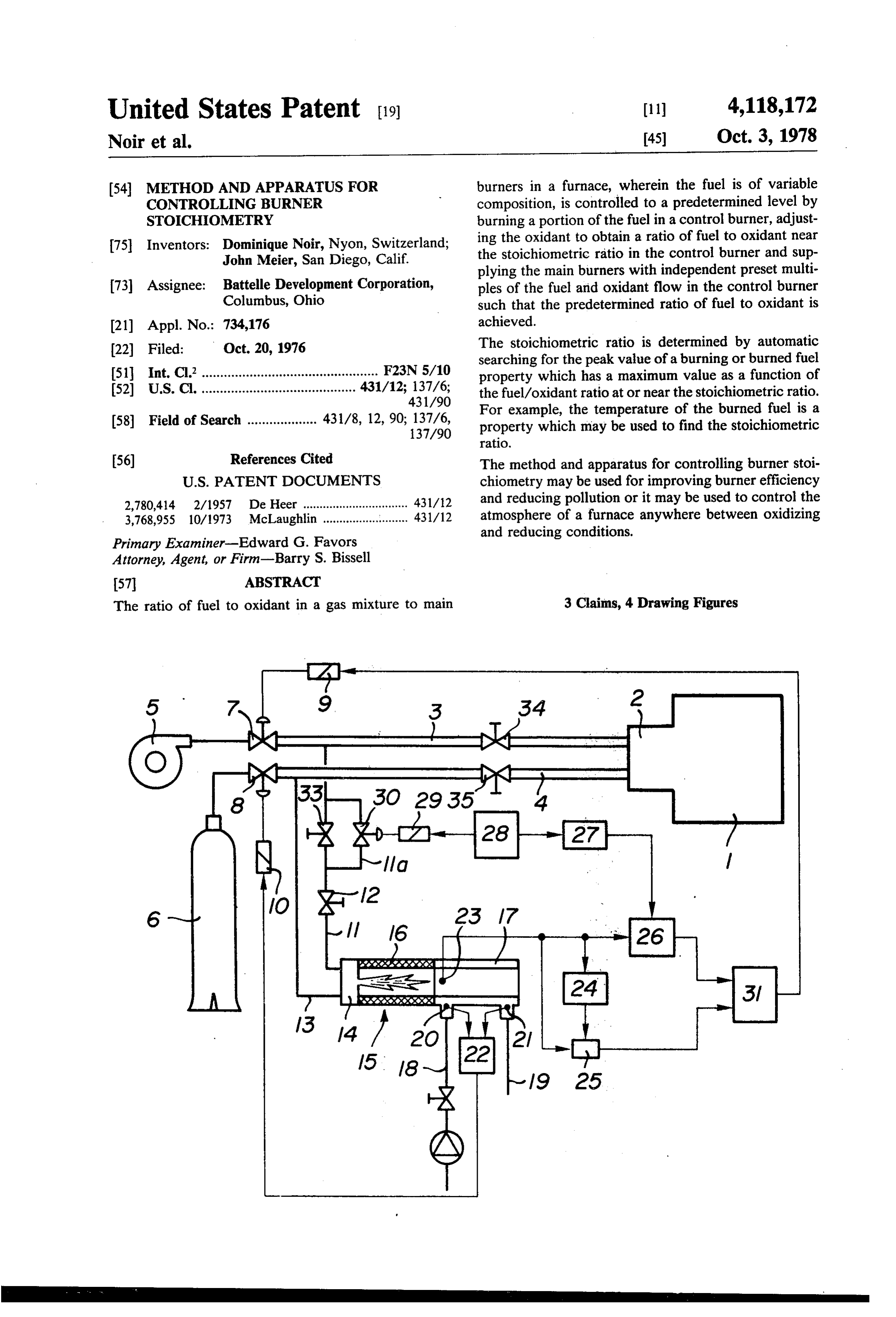
United States Patent (19) 11) 4,118,172 Noir et al. 45) Oct. 3, 1978 (54) METHOD AND APPARATUS FOR burners in a furnace, wherein the fuel is of variable CONTROLLING BURNER composition, is controlled to a predetermined level by STOICHOMETRY burning a portion of the fuel in a control burner, adjust 75 Inventors: Dominique Noir, Nyon, Switzerland; ing the oxidant to obtain a ratio of fuel to oxidant near John Meier, San Diego, Calif. the stoichiometric ratio in the control burner and sup plying the main burners with independent preset multi 73 Assignee: Battelle Development Corporation, ples of the fuel and oxidant flow in the control burner Columbus, Ohio such that the predetermined ratio of fuel to oxidant is (21) Appl. No.: 734,176 achieved.
22 Filed: Oct. 20, 1976 The stoichiometric ratio is determined by automatic searching for the peak value of a burning or burned fuel 51 Int. C.’................................................ F23N 5/10 property which has a maximum value as a function of 52 U.S. Cl. .......................................... 431/12; 137/6; the fuel/oxidant ratio at or near the stoichiometric ratio. 431/90 For example, the temperature of the burned fuel is a (58) Field of Search ................... 431/8, 12,90; 137/6, property which may be used to find the stoichiometric
(56) References Cited The method and apparatus for controlling burner stoi
2,780,414 2/1957 De Heer ................................ 431/12 and reducing pollution or it may be used to control the 3,768,955 10/1973 McLaughlin .......................... 431/12 atmosphere of a furnace anywhere between oxidizing and reducing conditions.
Primary Examiner-Edward G. Favors
Attorney, Agent, or Firm-Barry S. Bissell
The ratio of fuel to oxidant in a gas mixture to main 3 Claims, 4 Drawing Figures
Page 2
Drawing sheet — no readable text.
Page 3
Drawing sheet — no readable text.
Page 4
prevention rather than an attempted remedy of damag
METHOD AND APPARATUS FOR CONTROLLING ing variations in burning conditions caused by variation BURNER STOICHOMETRY in fuel composition and heating value (per standard BACKGROUND OF THE INVENTION volume of fuel).
It is another object of the invention to provide a
Maintaining constant temperatures and atmospheres method for burning variable calorific value fuel in an in furnaces, boilers, and other combustion chambers efficient manner in installations such as boilers, and in using gaseous hydrocarbons as the source of heat re also using the fuel for "non-efficient' combustion, such quires the employment of a fuel with a fairly constant as in controlled atmosphere furnaces. composition and heating value and an oxidant (usually O In accordance with the objectives, the invention is a air) in definite proportions to the fuel. Worldwide, the method and apparatus for continuously and automati use of producer gas, town gas, and other low, variable cally determining the stoichiometric ratio of oxidant to heating value gases has been superseded by the use of variable composition fuel in a control burner and con natural gas which has had an acceptably uniform heat tinuously supplying the main burners of a combustion ing value for most uses. However, present changes in 5 zone with preset multiples of the fuel and oxidant flow natural gas distribution toward large pipeline networks to the control burner, the preset multiples being related and regasification of liquified natural gas may result in to the deviation from the stoichiometric ratio desired in gas with some variation in composition. For most ther the combustion zone.
mal processes the magnitude of the variation may be The method for controlling the gaseous fuel to oxi acceptable; however, in others it may not. 20 dant ratio to a main burner employing variable compo Furthermore, the trend toward coal gasification will sition fuel comprises burning quantities of the fuel and once again introduce wider variations and low heating oxidant it a control burner, monitoring the change in value gas into industrial processes. A number of solu some property of the burning or burned gases which has tions exist for utilizing these variable heating value a peak value near the stoichiometric fuel to oxidant gases in thermal processes requiring constant heat. For 25 ratio, adjusting the quantities of fuel or oxidant to the example, one method involves constantly measuring the control burner to maximize the monitored property changes in temperature produced by the burning fuel of thereby finding the stoichiometric ratio for the oxidant variable calorific value and then varying the mass flow and the instantaneous fuel composition, and supplying of gaseous fuel to compensate for these changes. This is the main burner with preset multiples of the fuel and shown by U.S. Pat. No. 2,780,414 to De Heer wherein 30 oxidant flow in the control burner. The relative multi the temperature is also observed in an auxiliary burner. ples of fuel and oxidant to the main burner are deter Other U.S. Pat. Nos. to Kappel (2,818,246), Andrews mined from the desired variation from the stoichiomet (3,407,022), Dailey (2,866,602), and Schmidt (1,849,335; ric ratio established in the control burner. 1933,641; 2,349,521) disclose various ways of control The stoichiometric ratio of fuel to oxidant is found in ling air to fuel ratios in burning zones. However, they 35 the control burner by an automatic searching technique are directed mainly to controlling the amount of heat of a property of the burned or burning gases which has produced and not to controlling stoichiometry of the a peak value as a function of the fuel to oxidant ratio at gas and oxidant as is the present invention. or near the stoichiometric ratio. One way of automatic In ordinary burners wherein the ratio of air to fuel gas searching comprises periodically inducing a variation is mechanically fixed or wherein the air is admitted by (or pulse) in the fuel to oxidant ratio of the gases burned inspiration, the changing of the mass flow of fuel gas to in the control burner and comparing the direction of compensate for calorific variations can result in change in the monitored property with the direction of changed burning conditions and atmospheres inside the the change in the fuel to oxidant ratio. The deviation combustion zones. For example, rich fuel/air mixtures from the stoichiometric ratio may be determined from can result in pollutants in the form of unburned hydro 45 the relative changes of the two variables and a perma carbons and carbon monoxide and in a reducing atmo nent compensating change may be made to the fuel to sphere in the combustion zone. Lean mixtures can result oxidant ratio before inducing another pulse. Since the in an oxidizing atmosphere in the combustion Zone, monitored property has a maximum value near the stoi excessive nitrogen oxides and in heat losses as a result of chiometric ratio, it only remains to continue pulsing to having to heat excess air which is then lost in the ex 50 find the maximum value of the property, which is the haust. point where a small pulse results in little or no change in One present method of controlling the fuel to air ratio the monitored property.
consists of measuring the gas composition (particularly The above method for controlling burner stoichiome the oxygen level) of the exhaust gas with an analyzer try may be combined with temperature or heat respon and feeding the information back to the feed gas and air 55 sive means which can be used to determine the calorific lines to compensate for variations. In some processes, value of the variable fuel and adjust the flow of fuel to however, this remedial type of compensation can be the combustion zone to maintain the necessary heat for slow, and damage to the products being thermally the thermal conditioning. The above inventive method treated may occur before the change is made. In addi would then adjust the oxidant flow in response to the tion, some analyzers work only on the one side of the change in fuel flow to maintain the predetermined com stoichiometric ratio. bustion conditions (lean or rich) in the combustion zone.
SUMMARY OF THE INVENTION
Several rapid iterations of the sequence may be required to keep the combustion zone at both proper temperature
It is, therefore, an object of the present invention to and atmosphere.
provide a solution to the problem of controlling the 65 Apparatus according to the invention comprises ele amount of excess or deficiency of oxidant with respect ments for practicing the method including a control to the stoichiometric ratio of fuel and oxidant to burners burner, means for supplying fuel and oxidant to the in a combustion zone. The solution is in the way of control burner, means for measuring the burning prop
Page 5
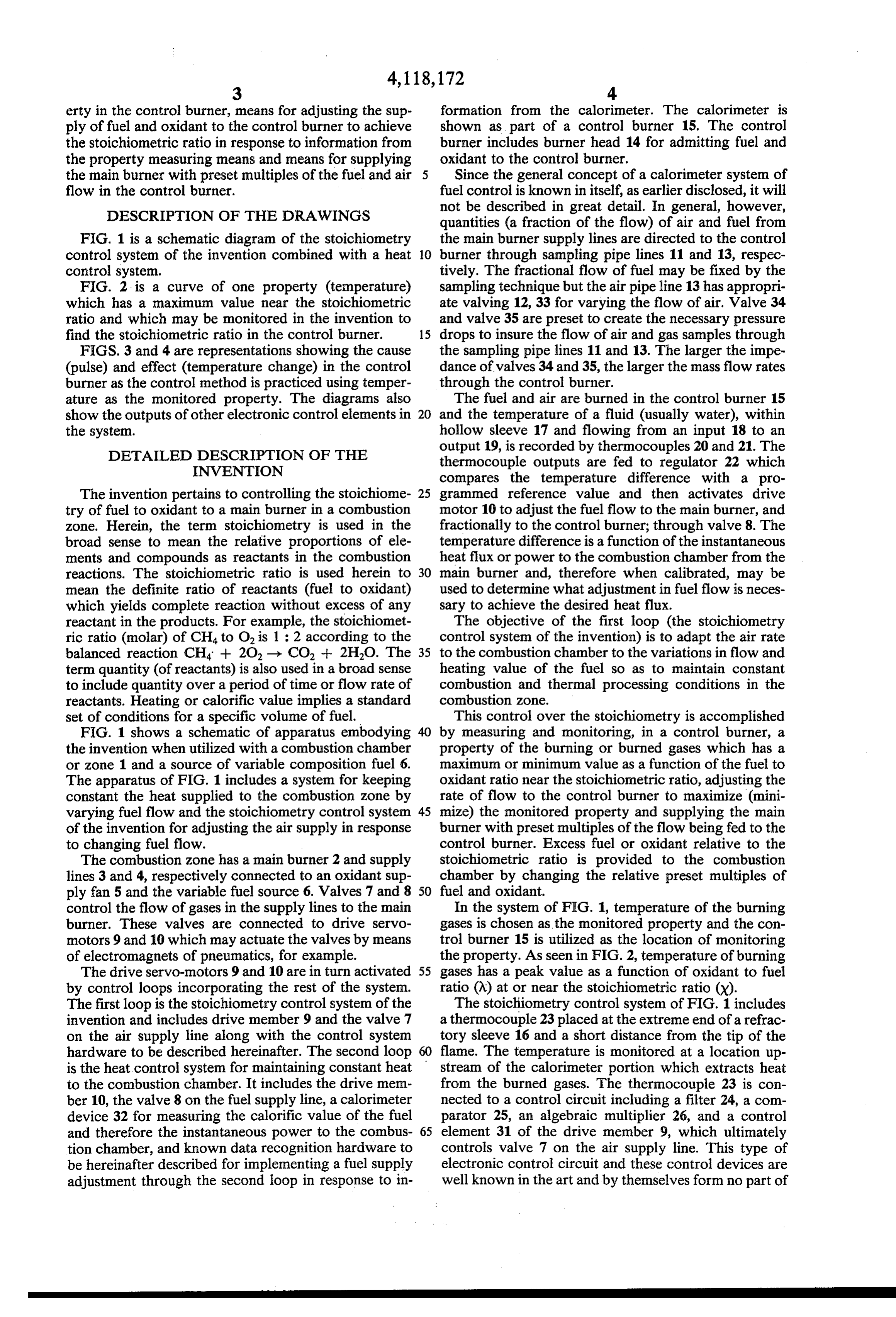
erty in the control burner, means for adjusting the sup formation from the calorimeter. The calorimeter is ply of fuel and oxidant to the control burner to achieve shown as part of a control burner 15. The control the stoichiometric ratio in response to information from burner includes burner head 14 for admitting fuel and the property measuring means and means for supplying oxidant to the control burner. the main burner with preset multiples of the fuel and air Since the general concept of a calorimeter system of flow in the control burner. fuel control is known in itself, as earlier disclosed, it will DESCRIPTION OF THE DRAWINGS not be described in great detail. In general, however, quantities (a fraction of the flow) of air and fuel from
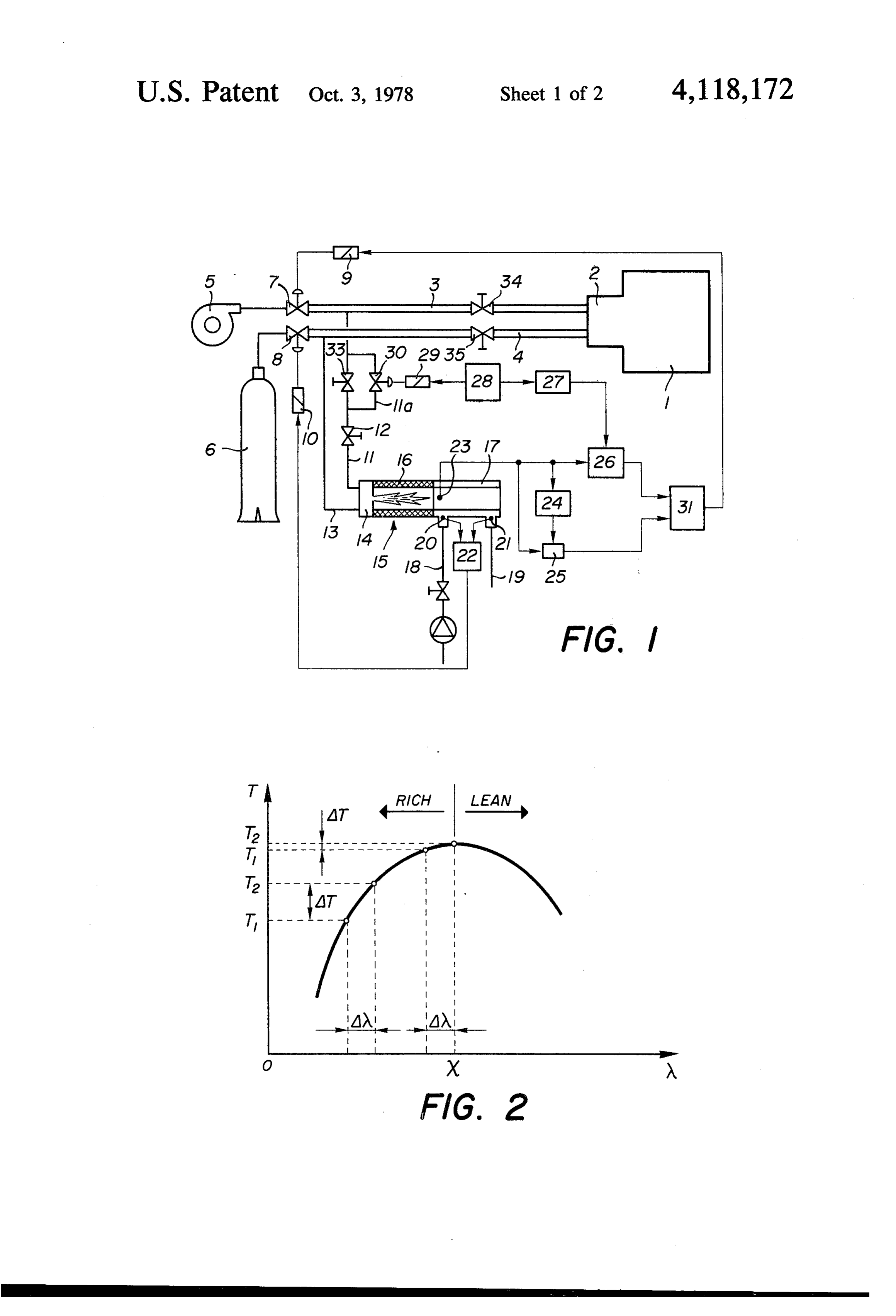
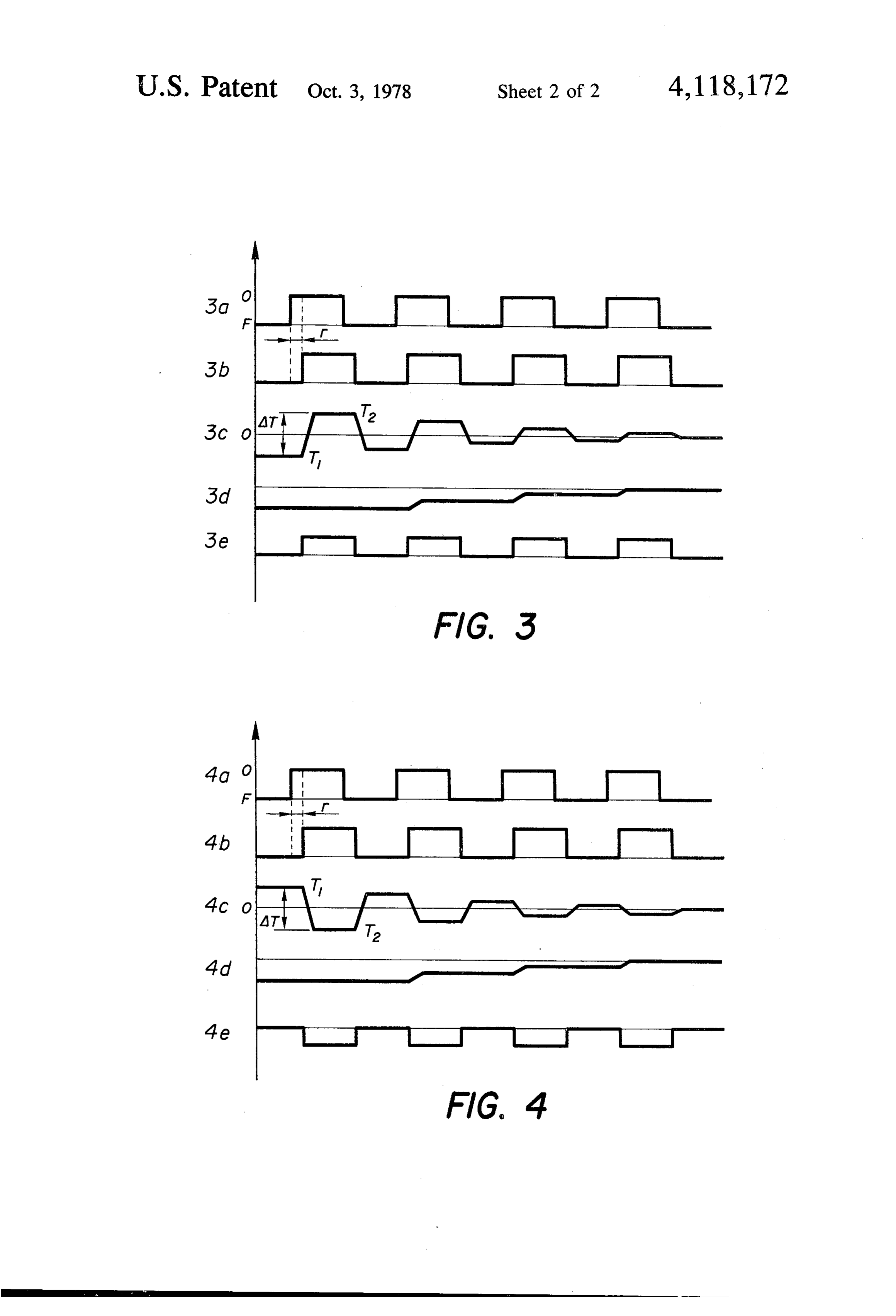
FIG. 1 is a schematic diagram of the stoichiometry the main burner supply lines are directed to the control control system of the invention combined with a heat 10 burner through sampling pipe lines 11 and 13, respec control system. tively. The fractional flow of fuel may be fixed by the FIG. 2 is a curve of one property (temperature) sampling technique but the air pipeline 13 has appropri which has a maximum value near the stoichiometric ate valving 12, 33 for varying the flow of air. Valve 34 ratio and which may be monitored in the invention to and valve 35 are preset to create the necessary pressure find the stoichiometric ratio in the control burner. 15 drops to insure the flow of air and gas samples through FIGS. 3 and 4 are representations showing the cause the sampling pipe lines 11 and 13. The larger the impe (pulse) and effect (temperature change) in the control dance of valves 34 and 35, the larger the mass flow rates burner as the control method is practiced using temper through the control burner.
ature as the monitored property. The diagrams also The fuel and air are burned in the control burner 15 show the outputs of other electronic control elements in 20 and the temperature of a fluid (usually water), within the system. hollow sleeve 17 and flowing from an input 18 to an DETAILED DESCRIPTION OF THE output 19, is recorded by thermocouples 20 and 21. The
INVENTION
thermocouple outputs are fed to regulator 22 which compares the temperature difference with a pro
The invention pertains to controlling the stoichiome 25 grammed reference value and then activates drive try of fuel to oxidant to a main burner in a combustion motor 10 to adjust the fuel flow to the main burner, and zone. Herein, the term stoichiometry is used in the fractionally to the control burner; through valve 8. The broad sense to mean the relative proportions of ele temperature difference is a function of the instantaneous ments and compounds as reactants in the combustion heat flux or power to the combustion chamber from the reactions. The stoichiometric ratio is used herein to 30 main burner and, therefore when calibrated, may be mean the definite ratio of reactants (fuel to oxidant) used to determine what adjustment in fuel flow is neces which yields complete reaction without excess of any sary to achieve the desired heat flux. reactant in the products. For example, the stoichiomet The objective of the first loop (the stoichiometry ric ratio (molar) of CH4 to O2 is 1 : 2 according to the control system of the invention) is to adapt the air rate balanced reaction CH4 + 20, -> CO2 + 2H2O. The 35 to the combustion chamber to the variations in flow and term quantity (of reactants) is also used in a broad sense heating value of the fuel so as to maintain constant to include quantity over a period of time or flow rate of combustion and thermal processing conditions in the reactants. Heating or calorific value implies a standard combustion zone.
set of conditions for a specific volume of fuel. This control over the stoichiometry is accomplished FIG. 1 shows a schematic of apparatus embodying by measuring and monitoring, in a control burner, a the invention when utilized with a combustion chamber property of the burning or burned gases which has a or zone 1 and a source of variable composition fuel 6. maximum or minimum value as a function of the fuel to The apparatus of FIG. 1 includes a system for keeping oxidant ratio near the stoichiometric ratio, adjusting the constant the heat supplied to the combustion Zone by rate of flow to the control burner to maximize (mini varying fuel flow and the stoichiometry control system 45 mize) the monitored property and supplying the main of the invention for adjusting the air supply in response burner with preset multiples of the flow being fed to the to changing fuel flow. control burner. Excess fuel or oxidant relative to the The combustion zone has a main burner 2 and supply stoichiometric ratio is provided to the combustion lines 3 and 4, respectively connected to an oxidant sup chamber by changing the relative preset multiples of ply fan 5 and the variable fuel source 6. Valves 7 and 8 50 fuel and oxidant.
control the flow of gases in the supply lines to the main In the system of FIG. 1, temperature of the burning burner. These valves are connected to drive servo gases is chosen as the monitored property and the con motors 9 and 10 which may actuate the valves by means trol burner 15 is utilized as the location of monitoring of electromagnets of pneumatics, for example. the property. As seen in FIG. 2, temperature of burning The drive servo-motors 9 and 10 are in turn activated 55 gases has a peak value as a function of oxidant to fuel by control loops incorporating the rest of the system. ratio (N) at or near the stoichiometric ratio (X). The first loop is the stoichiometry control system of the The stoichiometry control system of FIG. 1 includes invention and includes drive member 9 and the valve 7 a thermocouple 23 placed at the extreme end of a refrac on the air supply line along with the control system tory sleeve 16 and a short distance from the tip of the hardware to be described hereinafter. The second loop flame. The temperature is monitored at a location up is the heat control system for maintaining constant heat stream of the calorimeter portion which extracts heat to the combustion chamber. It includes the drive men from the burned gases. The thermocouple 23 is con ber 10, the valve 8 on the fuel supply line, a calorimeter nected to a control circuit including a filter 24, a com device 32 for measuring the calorific value of the fuel parator 25, an algebraic multiplier 26, and a control and therefore the instantaneous power to the combus 65 element 31 of the drive member 9, which ultimately tion chamber, and known data recognition hardware to controls valve 7 on the air supply line. This type of be hereinafter described for implementing a fuel supply electronic control circuit and these control devices are adjustment through the second loop in response to in well known in the art and by themselves form no part of
Page 6
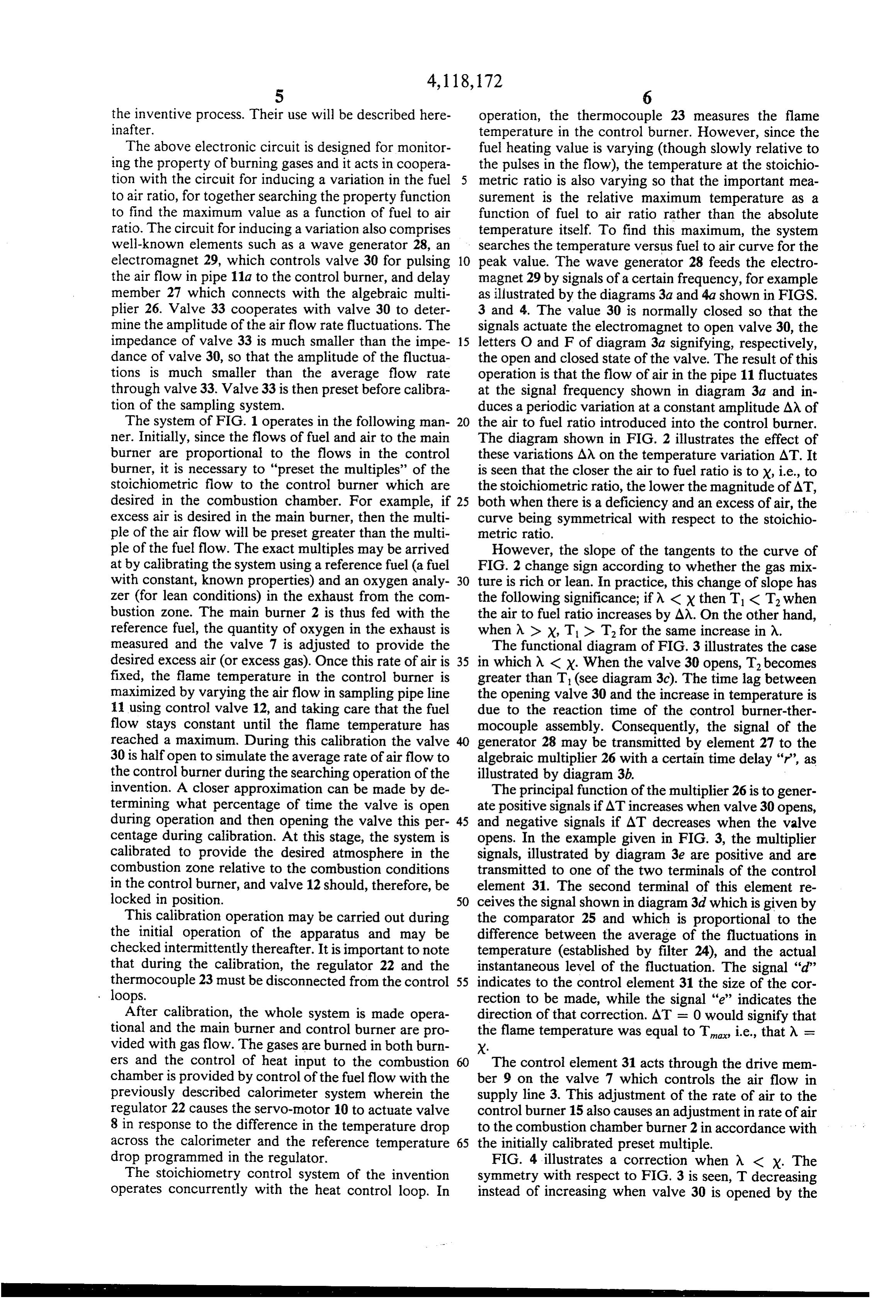
the inventive process. Their use will be described here operation, the thermocouple 23 measures the flame inafter. temperature in the control burner. However, since the The above electronic circuit is designed for monitor fuel heating value is varying (though slowly relative to ing the property of burning gases and it acts in coopera the pulses in the flow), the temperature at the stoichio tion with the circuit for inducing a variation in the fuel metric ratio is also varying so that the important mea to air ratio, for together searching the property function surement is the relative maximum temperature as a to find the maximum value as a function of fuel to air function of fuel to air ratio rather than the absolute ratio. The circuit for inducing a variation also comprises temperature itself. To find this maximum, the system well-known elements such as a wave generator 28, an searches the temperature versus fuel to air curve for the electromagnet 29, which controls valve 30 for pulsing 10 peak value. The wave generator 28 feeds the electro the air flow in pipe 11a to the control burner, and delay magnet29 by signals of a certain frequency, for example member 27 which connects with the algebraic multi as illustrated by the diagrams 3a and 4a shown in FIGS. plier 26. Valve 33 cooperates with valve 30 to deter 3 and 4. The value 30 is normally closed so that the mine the amplitude of the air flow rate fluctuations. The signals actuate the electromagnet to open valve 30, the impedance of valve 33 is much smaller than the impe 15 letters O and F of diagram 3a signifying, respectively, dance of valve 30, so that the amplitude of the fluctua the open and closed state of the valve. The result of this tions is much smaller than the average flow rate operation is that the flow of air in the pipe 11 fluctuates through valve 33. Valve 33 is then preset before calibra at the signal frequency shown in diagram 3a and in tion of the sampling system. duces a periodic variation at a constant amplitude AM of The system of FIG. 1 operates in the following man 20 the air to fuel ratio introduced into the control burner. ner. Initially, since the flows of fuel and air to the main The diagram shown in FIG. 2 illustrates the effect of burner are proportional to the flows in the control these variations AM on the temperature variation AT. It burner, it is necessary to "preset the multiples' of the is seen that the closer the air to fuel ratio is to X, i.e., to stoichiometric flow to the control burner which are the stoichiometric ratio, the lower the magnitude of AT, desired in the combustion chamber. For example, if 25 both when there is a deficiency and an excess of air, the excess air is desired in the main burner, then the multi curve being symmetrical with respect to the stoichio ple of the air flow will be preset greater than the multi metric ratio.
ple of the fuel flow. The exact multiples may be arrived However, the slope of the tangents to the curve of at by calibrating the system using a reference fuel (a fuel FIG. 2 change sign according to whether the gas mix with constant, known properties) and an oxygen analy 30 ture is rich or lean. In practice, this change of slope has zer (for lean conditions) in the exhaust from the com the following significance; if N < x then T. < T, when bustion zone. The main burner 2 is thus fed with the the air to fuel ratio increases by AA. On the other hand, reference fuel, the quantity of oxygen in the exhaust is when A > X, Tid T. for the same increase in A. measured and the valve 7 is adjusted to provide the The functional diagram of FIG. 3 illustrates the case desired excess air (or excess gas). Once this rate of air is 35 in which X < x. When the valve 30 opens, T. becomes fixed, the flame temperature in the control burner is greater than T (see diagram 3c). The time lag between maximized by varying the air flow in sampling pipe line the opening valve 30 and the increase in temperature is 11 using control valve 12, and taking care that the fuel due to the reaction time of the control burner-ther flow stays constant until the flame temperature has mocouple assembly. Consequently, the signal of the reached a maximum. During this calibration the valve generator 28 may be transmitted by element 27 to the 30 is half open to simulate the average rate of air flow to algebraic multiplier 26 with a certain time delay "r', as the control burner during the searching operation of the illustrated by diagram 3b.
invention. A closer approximation can be made by de The principal function of the multiplier 26 is to gener termining what percentage of time the valve is open ate positive signals if AT increases when valve 30 opens, during operation and then opening the valve this per 45 and negative signals if AT decreases when the valve centage during calibration. At this stage, the system is opens. In the example given in FIG. 3, the multiplier calibrated to provide the desired atmosphere in the signals, illustrated by diagram 3e are positive and are combustion zone relative to the combustion conditions transmitted to one of the two terminals of the control in the control burner, and valve 12 should, therefore, be element 31. The second terminal of this element re locked in position. 50 ceives the signal shown in diagram 3d which is given by This calibration operation may be carried out during the comparator 25 and which is proportional to the the initial operation of the apparatus and may be difference between the average of the fluctuations in checked intermittently thereafter. It is important to note temperature (established by filter 24), and the actual that during the calibration, the regulator 22 and the instantaneous level of the fluctuation. The signal "d” thermocouple 23 must be disconnected from the control 55 indicates to the control element 31 the size of the cor loops. rection to be made, while the signal "e" indicates the After calibration, the whole system is made opera direction of that correction. AT = 0 would signify that tional and the main burner and control burner are pro the flame temperature was equal to T, i.e., that M = vided with gas flow. The gases are burned in both burn X.
ers and the control of heat input to the combustion The control element 31 acts through the drive mem chamber is provided by control of the fuel flow with the ber 9 on the valve 7 which controls the air flow in previously described calorimeter system wherein the supply line 3. This adjustment of the rate of air to the regulator 22 causes the servo-motor 10 to actuate valve control burner 15 also causes an adjustment in rate of air 8 in response to the difference in the temperature drop to the combustion chamber burner 2 in accordance with across the calorimeter and the reference temperature 65 the initially calibrated preset multiple. drop programmed in the regulator. FIG. 4 illustrates a correction when A < x. The The stoichiometry control system of the invention symmetry with respect to FIG. 3 is seen, T decreasing operates concurrently with the heat control loop. In instead of increasing when valve 30 is opened by the
Page 7
signal "a", and the algebraic multiplier 26 producing a value as a function of the fuel to oxidant ratio at negative signal 'e'. about the stoichiometric ratio, Once again, it is emphasized that the apparatus uti (C) adjusting the fuel to oxidant ratio to the control lized in the invention are generally known. The inven burner to substantially maximize the magnitude of tion is the combination of the elements and steps which the monitored property by the steps comprising allows the maintenance of constant combustion condi (a) periodically inducing a variation in the fuel to tions when using variable composition fuels without the oxidant ratio in the control burner, time and expense of measuring the mass flow of the fuel (b) measuring the direction of the change in the or the fuel composition. magnitude of the monitored property, As alternatives in the above described example of the O (c) comparing the direction of the change in the invention it is possible and sometimes desirable to moni magnitude of the monitored property with the tor a property other than temperature in the stoichiome variation in fuel to oxidant ratio to the control try control loop. For example, other properties which burner whereby to determine whether the have peak values, as a function of the fuel to oxidant change in magnitude of the monitored property ratio, near the stoichiometric ratio include: the amount 15 is characteristic of an excess of fuel or oxidant of water vapor or carbon dioxide in the burned gases, with respect to the stoichiometric ratio, the degree of ionization in the burned gases, flash-back (d) varying the quantity of fuel or oxidant in the velocity gradient, blow-off velocity gradient, heat flux control burner to substantially eliminate the ex and quenching distance. The latter property has a mini cess of fuel or oxidant with respect to the stoi mum value near the stoichiometric ratio, and the search 20 chiometric ratio, and technique can be used to find the minimum value of the (D) simultaneously supplying said main burner with property or the maximum of the inverse property. independent, preset multiples of the quantity of fuel Instruments for measuring these properties and oth and the quantity of oxidant in the control burner ers are well-known in the art. Such measurements might such that said predetermined stoichiometry to the be more desirable than temperature because of the lag in 25 main burner is maintained. the response time and the poisoning of the thermo 2. The method for providing a predetermined instan couple during the temperature measurement. taneous excess air and maintaining a predetermined In the searching operation it is equally possible to temperature pulse the fuel flow rather than the airflow. The temper mixture of a output in a main burner fed with a gaseous quantity of air and a quantity of a variable ature variation should then vary in the opposite direc 30 composition or variable heating value fuel comprising tion to the variation caused by an air pulse.
Additionally, the shape of the signal from the wave the(A) steps of:
burning a fixed fraction of the quantity of fuel and generator need not be a square wave as shown in FIGS. a fixed fraction of the quantity of air in a control 3 and 4. Any output which is sufficient to periodically burner, such fixed fractions of fuel and air being pulse the flow of fuel or oxidant to the control burner 35 related such that for a reference fuel the fixed frac according to the invention is sufficient to function in the tions of fuel and air are in stoichiometric ratio system.
The heat control loop with the calorimeter was de when the quantity of air to the main burner is in scribed as functioning by adjusting the fuel in response predetermined excess to the quantity of fuel to the to variable heating value gas. Actually, this loop might main burner.
also adjust the air to a first approximation and then (B) measuring the temperature produced by the burn allow the stoichiometry control loop to fine tune the air ing in the control burner, flow. This would be useful for programmed changes in (C) adjusting the quantity of fuel fed to the main the heat flux demand to the combustion chamber. burner such that the difference in the predeter The above described control system is useful in com 45 mined temperature and the temperature produced bustion systems wherein thermal processing requires in the control burner is substantially eliminated, critical atmospheric conditions. It is also useful in ther (D) monitoring the magnitude of a property of the mal processes requiring reducing or non-oxidizing at burning or the burned fuel and air in the control mospheres, and it is useful in any systems where conser burner, said monitored property having a maxi vation of fuels through efficient combustion is desired. 50 mum value as a function of the fuel to air ratio at These uses suggest several possible systems, for exam about the stoichiometric ratio, ple, large-scale atmosphere gas generators, catalytic (E) adjusting the fuel to air ratio to the control burner reformers for hydrogen production, gaseous feedstock to substantially maximize the magnitude of the control systems in chemical and petrochemical indus monitored property by the steps comprising tries such as ammonia production, refinery heater com 55 (a) periodically inducing a variation in the fuel to bustion systems using refinery off-gases as fuel and in air ratio to the control burner, dustrial boilers fired by large single burners or sepa (b) measuring the direction of the change in the rately piped multiple burners. magnitude of the monitored property, We claim: (c) comparing the direction of the change in the 1. A method for continuously controlling a gaseous monitored property with the variation in the fuel mixture comprising an oxidant and a fuel of variable to air ratio to the control burner whereby to composition or variable heating value to a predeter determine whether the change in magnitude of mined stoichiometry in a main burner comprising, the monitored property is characteristic of an (A) burning a quantity of the fuel and the oxidant in excess of fuel or air with respect to the stoichio a control burner in parallel with said main burner, 65 metric ratio, and
(B) monitoring the change in magnitude of a property (d) varying the quantity of fuel or air to the main of the burning or the burned fuel and oxidant in the burner to proportionally vary the quantity of control burner, said property having a maximum fuel or air to the control burner to substantially
Page 8
eliminate the excess of fuel or air with respect to (a) means for periodically inducing a variation of the stoichiometric ratio. the fuel to oxidant ratio in the control burner, 3. Apparatus for continuously controlling a gaseous (b) means for comparing the direction of the mixture comprising an oxidant and a variable composi- change in the magnitude of the monitored prop tion or variable heating value fuel to a predetermined erty with the variation in the fuel to oxidant ratio stoichiometry in a main burner comprising, in the control burner whereby to determine (A) a control burner separate from and in parallel whether the change in magnitude of the moni with the main burner, tored property is characteristic of an excess of (B) means for supplying metered quantities of fuel 10 fuel or oxidant with respect to the stoichiometric ratio, and and oxidant to the control burner, (c) means for varying the fuel to oxidant ratio in the (C) means for monitoring the change in magnitude of control burner for reducing the excess of fuel or a property of burning or burned quantities of fuel oxidant with respect to the stoichiometric ratio and oxidant in the control burner, said property in response to information from the means for having a maximum value as a function of the fuel to 15 comparing, and oxidant ratio at about the stoichiometric ratio, (E) means for simultaneously supplying the main (D) means for adjusting the fuel to oxidant ratio to burner with independent, preset multiples of the about the stoichiometric ratio in the control burner quantity of fuel and the quantity of oxidant in the in response to information from the means for mon- control burner such that said predetermined stoi itoring said property in the control burner compris- 20 chiometry to the main burner is maintained. ing k is
Provenance
- Collection
- Cited prior art
- Original PDF
- patentimages.storage.googleapis.com →
- Filed
- 1976-10-20
- Pages
- 8
- Method
- pdftotext (the PDF's own text layer) + pdftoppm 300dpi page scans
- Source
- Google Patents bibliographic record
- Granted
- 1978-10-03
- Inventors
- Dominique Noir; John Meier; Battelle Development Corp
- Transcribed from
- patentimages.storage.googleapis.com →