patent · US4097225
Process and apparatus for calcining limestone
27 June 1978
Page 1 — bibliographic record
United States Patent (19) (11) 4,097,225 Rourke 45 Jun. 27, 1978 54 PROCESS AND APPARATUS FOR (56) References Cited CALCINING LIMESTONE U.S. PATENT DOCUMENTS s 1,243,311 10/1917 Loder ..................................... 432/96 (76) Inventor: Terence Arthur Rourke, Upper Long 3,584,849 6/1971 Cremer et al. ......................... 432/25
swives 2/1972 LadO . . . . . . . . . . . . . . . . . . . . . . . . . . . . . . . . . . . . 432/17
Columbia, Canada, VIP5P6 3,721,728 3/1973 Luetzelschwab ...................... 432/25 3,756,768 9/1973 Escott .................................... 432/17 21 Appl. No.: 760,112 3,887,326 6/1975 Townley ................................ 432/17 Primary Examiner-John J. Camby 22 Filed: Jan. 17, 1977 Attorney, Agent, or Firm-Richard J. Hicks; Stanley E. Johnson
Related U.S. Application Data 57 ABSTRACT 63 Continuation of Ser. No. 658,576, Feb. 17, 1976, Pat. A process and apparatus for burning limestone to pro No. 4,031,183, which is a continuation-in-part of Ser. duce calcined lime in which limestone is burned contin No. 559,193, Mar. 17, 1975, abandoned. uously in a vertical kiln provided with a plurality of fuel injectors which permit pulsed introduction of fuel so as 51 Int. Cl. ............................................. F27B 1/26 to ensure a lamellar flow of fuel through the kiln and a 52 U.S. Cl. ........................................ 432/96; 432/25 controlled release of heat.
58) Field of Search ....................... 432/17, 25, 51, 95, 432/96; 269/187 7 Claims, 6 Drawing Figures
Lopes 3. in Probuct in PERCeNT
10 SSSI.
5 SSIS
222ZZZZZZZZZA log 50 an M24/ZZZZ AZZVAWA/AW/V
ad SS se ZZZZZZZZYZVZ a / We
2 SSSAA2222222222244AAAAAA' d s YZA22222222AZAZAAAAAAYAT 2 so o 8 SSS
AZZZZZZZZZZZZZZAZZAA/YA/ ?2
Esg 2ZZZZZZZZZYYZAZ7777AAAWAA/V 5t
CARDON Dioxide N Ex-AUST GAO4-05 CARDON MONOXD
Page 2
Drawing sheet — no readable text.
Page 3
Drawing sheet — no readable text.
Page 4
Drawing sheet — no readable text.
Page 5
Drawing sheet — no readable text.
Page 6
rotary kilns of modern design require 5.5-10 million
PROCESS AND APPARATUS FOR CALCINING BTU/ton, vertical kilns of the Azbe type 5-7 million LMESTONE BTU/ton, double incline vertical kilns about 4.1 million BTU/ton and rotary hearth kilns of the Calcimatic type
This is a continuation of application Ser. No. 658,576 5 5.1-5.5 million BTU/ton, Schmid-Hoffer regenerative now U.S. Pat. No. 4,031,183 filed Feb. 17, 1976, which kilns 3.2 million BTU/ton and mixed feed kilns 3-5 in turn is a continuation-in-part of application Ser. No. million BTU/ton.
559,193 filed Mar. 17, 1975 (now abandoned). An object of the present invention is to provide a This invention relates to a process and apparatus for vertical kiln for calcining limestone with a lower heat calcining limestone. More particularly the invention O requirement than heretofore believed possible. relates to a novel vertical kiln for calcining limestone Another object of the present invention is to provide and a process of operation thereof. a process for producing calcined lime in a vertical kiln Limestone is a general term embracing carbonate of novel design so as to use only an amount of heat rocks or fossils and is primarily calcium carbonate or a approaching the theoretical minimum. combination of calcium and magnesium carbonate with 15 Thus, by one aspect of the invention there is provided varying amounts of impurities such as silica and alu a process for the continuous production of calcined lime mina. In contrast, lime is invariably derived from lime from limestone in a vertical kiln in which fuel is sup stone and is a calcined or burned form of limestone, plied through a plurality of injectors circumferentially usually known as quicklime or hydrated lime. During spaced around the kiln in a single horizontal plane calcination of limestone water and carbon dioxide are 20 spaced from the lower end of the kiln and combustion expelled forming calcium oxide (quicklime) and when air water is added thereto calcium hydroxide (hydrated or tors,is counter supplied to said kiln, from a level below said injec current to the flow of limestone, compris slaked lime) is produced. While limestone, quicklime 1ng:
and hydrated lime have some similarities in character, properties and uses, it is emphasized that this invention 25 (a)inches charging limestone ranging in size up to about five to the top of said kiln for downward move is primarily concerned with quicklime and a novel pro ment therethrough;
cess and apparatus for producing it. (b) continuously blowing air upwardly through said Quicklime has been known for many centuries and kiln in an amount sufficient to support combustion; vast quantities are consumed annually throughout the (c) injecting fuel at a relatively high pressure through world in a wide range of uses as diverse as metallurgical 30 each of said injectors in a predetermined sequence flux and as an absorbent. The uses of lime are second at a rate between 100 and 500 injections per injec only to sulphuric acid as an industrial chemical. tor per minute, each of said injections occurring in As varied as the uses of lime are the processes and a time period between 0.02 and 0.2 seconds thereby apparatus which have been developed for producing it, establishing an initial lamellar flow of fuel and air in from Ancient Egyptian times to the present. The pro 35 said kiln; and cesses range from burning heaps of limestone to use of (d) withdrawing calcined lime at the lower end of intermittent and continuous vertical kilns; horizontal said kiln.
rotary kilns; flu-solids kilns; and circular refractory By another important aspect of the invention there is hearths; many of which have been adapted for opera provided an apparatus for the production of calcined tion with fuels as diverse as wood, oil, coal, coke or natural gas depending upon local costs and availability, lime comprising: a refractory line vertical shaft pro vided with material feed means and gas exhaust means;
the object always being to obtain the maximum output cooler means secured to and in communication with the of lime for a given input of heat, while recognizing that the heat supplied must be uniformly distributed and lower end of said vertical shaft and provided with excessively high flame temperatures avoided. Most 45 means to withdraw calcined lime from said apparatus; means for admitting air into said cooler; a draw feeder modern processes can be divided into three stages, plate mounted between said cooler and said shaft so as namely, preheating, calcination and cooling. Waste heat to provide from the cooling stage is, of course, used in the air means mounted a baffle means therebetween; a draw feeder preheat stage and fuel is normally only supplied in the through said lower end of said shaft and calcination stage. It has been determined theoretically 50 adapted to draw material on said feeder plate into said that the minimum heat requirement to convert 100% cooler; a plurality of injector means spaced around said pure calcium carbonate to lime is 2.77 million BTU/ton shaft thereof in a horizontal plane spaced from said lower end for introducing fuel into said shaft; and means plus 1.6 million BTU/ton to heat the stone to the disso ciation temperature (1648 F898 C). By convention, for supplying fuel at relatively high pressure to each of however, the preheating figure is not included as a 55 said injector means at a rate between 100 and 500 injec portion of the heat requirement as, theoretically, it oc tions per minute.
The invention will be described in more detail herein curs only once on warming the first charge of lime stone, from then on the BTU recovery from the gases below with reference to the accompanying drawings in leaving the calcining stage serves predominantly to which:
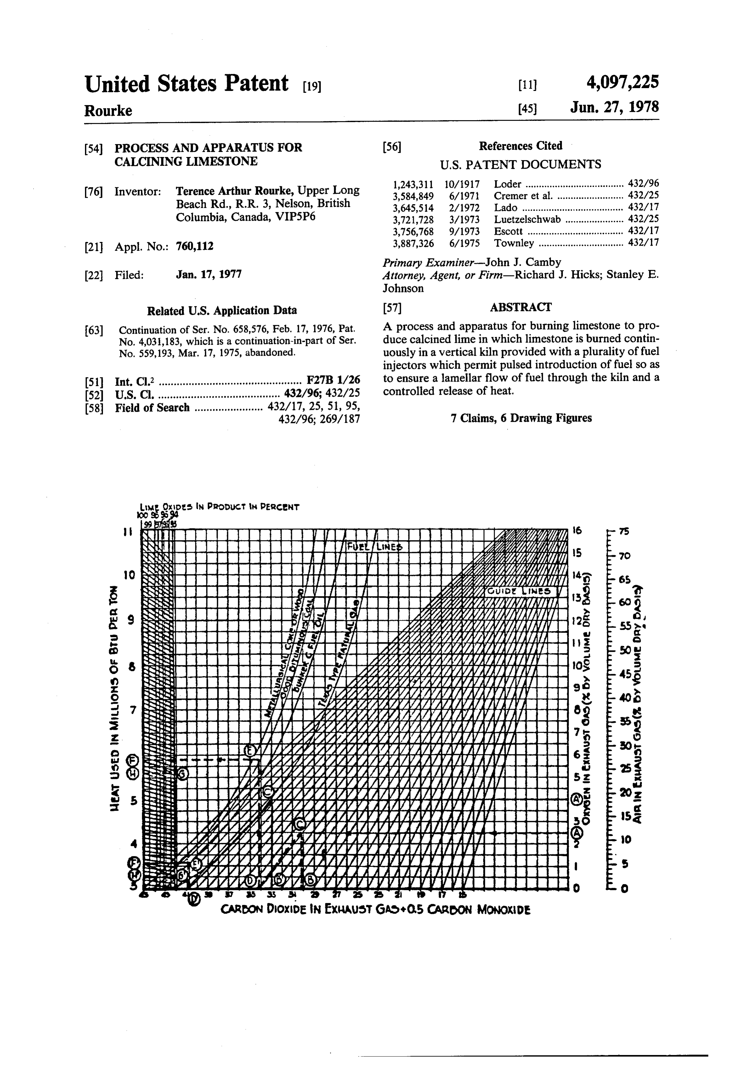
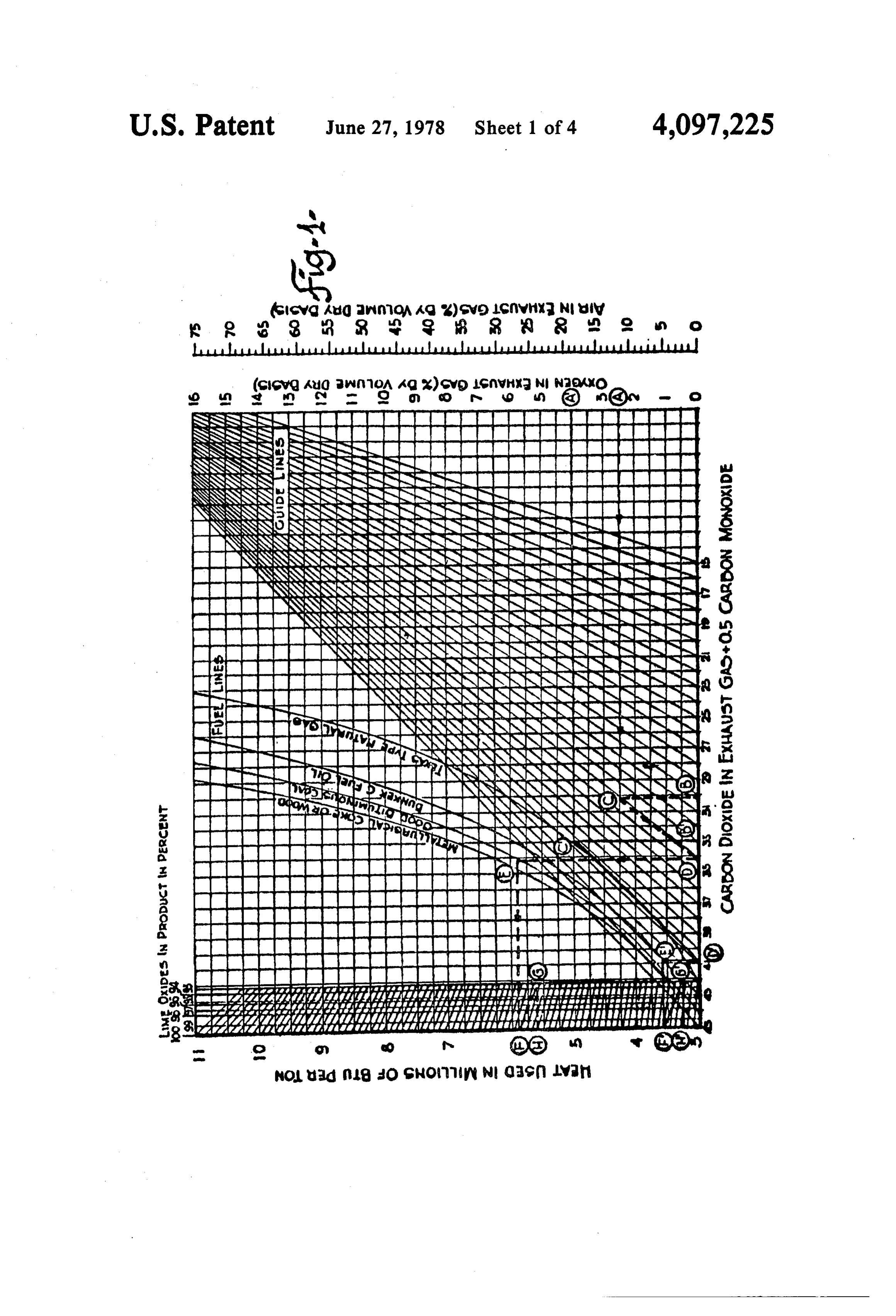
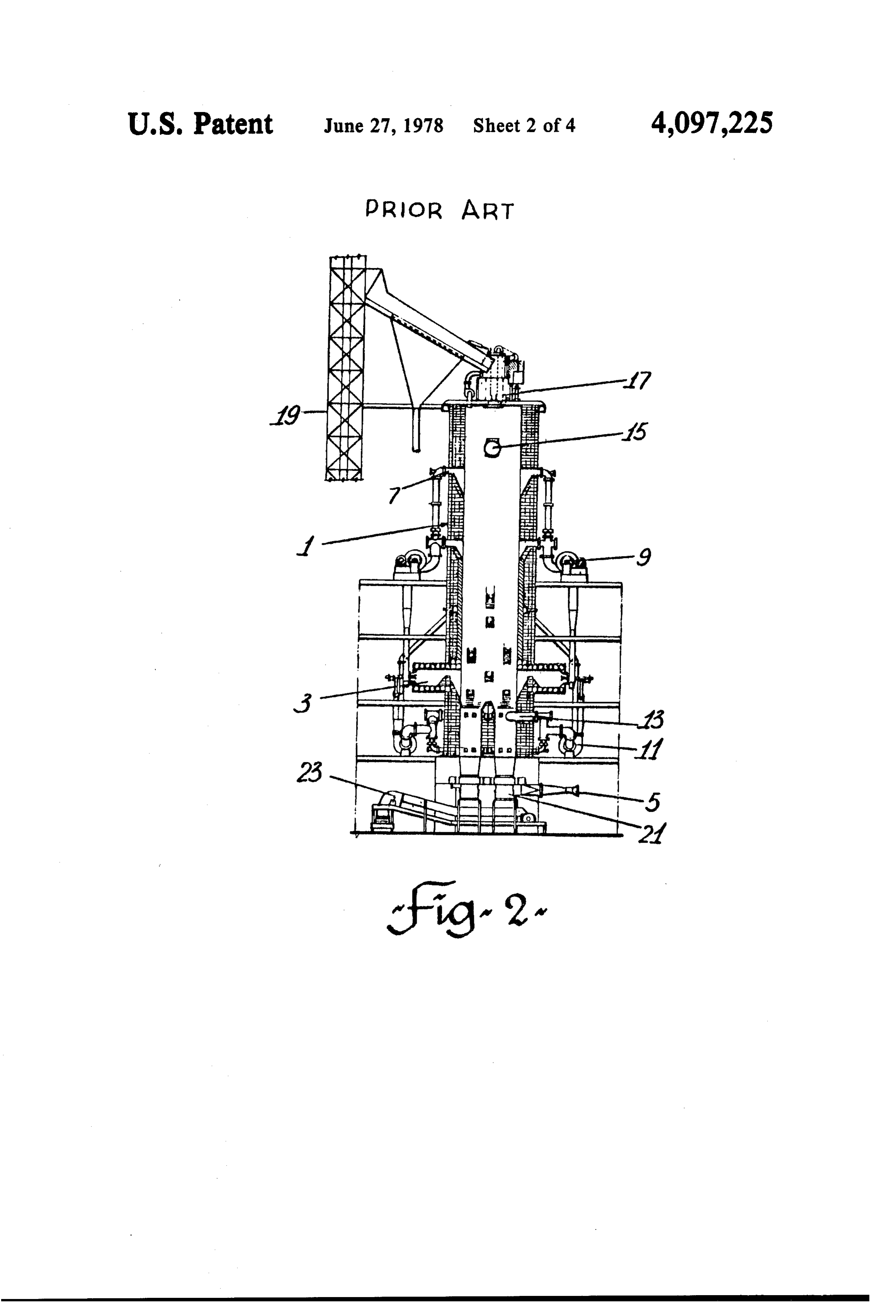
preheat successive charges. Naturally, 100% efficiency FIG. 1 is a graph for calculation of kiln thermal effi is unattainable, due largely to three reasons. Firstly, ciency from waste gas analysis (from Azbe, Rotary Kiln there is no commercial limestone available at 100% Evaluation and Development, Rock Prod. Mar. 1954). purity; secondly, it is impossible to calcine lime without FIG. 2 is a schematic view of an Azbe high capacity some dissipation of heat calories; and thirdly, produc vertical kiln, representative of the prior art. tion of lime with zero core of unburned stone and recar 65 FIG. 3 is a schematic view of an Aton-Hansen Im bonation, without hard burning, is virtually impossible. pulse Burner kiln.
Over the years the heat" requirements of the various FIG. 3a is a schematic flow chart showing the full types of kilns have been steadily reduced so that today injection cycles in a kiln as shown in FIG. 3.
Page 7
FIG. 4 is a vertical section through a simplified ver that much work including the present invention has sion of a kiln according to the present invention. been directed.
FIG. 5 is a plan view of a kiln according to the pres Attempts to simulate the slow-burning characteristics ent invention taken along a line 4-4 in FIG. 3. of wood have included the use of impulse-firing in an Turning firstly to FIG. 1, which illustrates thermal Aton (R)-Hansen vertical kiln such as that illustrated in efficiency of a kiln from waste gas analysis, and which FIG. 3 and described by Von R. Rittmann in Zement is described in detail in Boynton "Chemistry and Tech Kalk-GIPS, No. 5, 1970. A vertical lime kiln 51, nology of Lime and Limestone', John Wiley and Sons, charged with limestone in the 2-4 inches or greater size Inc., 1966, let us assume that high calcium quick-lime is range, is provided with a plurality of burners or injec burned with high grade coal in an Azbe type kiln of the 10 tion nozzles 52, 0.5-1.5 mm in diameter, arranged in type depicted in FIG. 2, and that the exhaust gases two, three of four parallel horizontal planes (shown as 3 contain 2.5% O2, shown at A, and 30.1% CO2, shown at planes 53, 54 and 55 in FIG. 3). Conveniently, but not B. A horizontal line is drawn from A which intersects essentially, three burners are provided in each plane, the vertical line from B at C. To allow for the 2.5% O2, arranged symmetrically around the circumference of the "equivalent CO,” is obtained by drawing a line 15 the kiln but with the burners in each plane being cir which is drawn diagonally down to D at 34.2% in paral cumferentially displaced from the burners in the other lel with the guide lines. Next, a vertical line is extended two planes, as shown in FIG. 3a. The supply of oil to up to E, where it intersects the gradient representing individual burners is electronically controlled as by coal fuel. Adjusting for different fuels, observe the controller 56 so as to provide a pulse of oil to each other fuel gradients for coke, oil and natural gas, which 20 burner in each plane in turn, as illustrated in FIG. 3a, so compensate for their different thermal values. Then a that, for example, in the first cycle fuel is provided at horizontal line is extended to the left ordinate at F, burners 3, 2 and 1 in levels 53, 54 and 55, respectively. indicating a fuel consumption of 5.8 million BTU/ton. In the second cycle, fuel is provided at burners 1, 3 and Assuming a CaO content of 95%, then a diagonal line is 2 in levels 53, 54 and 55, respectively, and in the third drawn to G, where it bisects the 95% vertical line. A 25 cycle fuel is provided at burners 2, 1 and 3 in levels 53, horizontal line to H finally reveals a net fuel consump 54 and 55, respectively. The oil is vapourized in the tion of 5.6 million BTU/ton. If the exhaust gases had burners and is mixed with combustion air 58 fed up also contained CO, allowance would be made at point B wardly from below, so that it burns in a kidney-shaped by adding 0.5% of CO, for every percent of CO to burning zone in front of each burner for approximately redetermine an equivalent CO2. 30 one-third of each cycle. It is claimed that this system of When excess air is used in combustion, CO2 in the exit impulse burning requires less than 1000 kcal per kg of gases may be reduced and O, content increased - or lime and can produce 1.25 tons per sq. ft. of kiln diame incomplete combustion results with less CO, and forma ter per day. The system is, however, limited to rela tion of CO. Both situations dissipate heat and this is why tively large sized limestone because of penetration diffi the determination of equivalent CO is important, be 35 culties and the low pressures required to keep the burn cause it reconstructs theoretically the amount of CO2 ing Zone adjacent the burners. Even with three planes of that would be present if combustion was balanced and burners it has not been found possible to achieve the there was no surplus of air. Generally, the higher the lamellar flow of fuel as described hereinafter with refer CO, is in the exhaust gases, the higher the thermal effi ence to the present invention, which has been found ciency. particularly successful in achieving high throughputs of FIG. 2 represents a typical Azbe kiln of the prior art, lime with minimum heat input. The cycle time in the and consists of a brick-lined vertical kiln 1, provided Aton (E)-Hansen system is such that the individual with an oil burning chamber 3; air inlets 5; a hot air pulses of fuel, normally oil, are relatively long in con recycling system comprising hot air outlets 7, hot air parison to the complete cycle and at relatively low recycling fans 9, 11 and recycled air inlets 13; a waste 45 pressure.
gas exhaust 15; a stone charging device 17 fed via a skip Lamellar flow is a term used herein to describe a and bucket system 19; and a hydraulic draw feeder 21 three-stage cycle for fuel burning wherein, in the first for withdrawing calcined lime from the bottom of the stage there is an almost instantaneous injection of fuel kiln and feeding to a lime conveyor 23. Although this (0.02 to 0.2 seconds) at a relatively high pressure (in the kiln is shown as being oil-fired, relatively minor modifi 50 range 2,000 to 15,000 psi and preferably 6,000 to 8,000 cations only are necessary to operate the kiln on gas, psi at the nozzle) through a nozzle of a plurality of wood or coal. Wood, if available at reasonable cost, is in nozzles spaced in a single horizontal plane around the fact the ideal fuel in a kiln of this type because it pro circumference of the kiln, and used sequentially in a duces a longer flame than other solid, liquid or gaseous predetermined sequence, into the mass of hot lime in fuels, enabling the heat to be released farther into the 55 front of the injector in order to totally flood this area stone mass and creating a broader lower temperature with fuel and in so doing exclude all combustion air burning zone. This maximizes kiln capacity and pro from the area. In the second stage, after the short pulse motes more uniform calcination and soft burned line. of fuel, there is a relatively much longer period of time Considerable steam is generated from wood, more than (0.1 to 0.5 seconds) before the next fuel pulse during any other fuel, contributing a tempering effect that 60 which combustion air, under the differential pressure lowers the flame temperature required for calcination. existing between the bottom and top of the kiln, moves The resulting cooler temperature reduces the danger of upwardly and displaces the fuel zone above it. In the overburning. Thus lime makers who are forced to use third stage, there is a gradual breakdown in the bound other fuels for reasons of economics or availability al aries between the upwardly moving air and fuel zones ways strive to approximate the characteristics of wood 65 So that combustion starts to make place and heat is burning. It is believed that of all of the factors affecting gradually released at a point removed from the injection efficient lime-burning, the slow controlled release of nozzle. The cycle is then repeated with the next nozzle heat in the kiln is the most important, and it is to this end in the sequence. It will, of course, be appreciated that
Page 8
rapid, pulsed fuel injection to a bed of incandescent be treated, depending on kiln size and specific operating limestone will, in effect, cause a series of minor explo techniques. Combustion air is introduced through a sions within the kiln, in a manner analagous to the firing valve 49 and inlet 41 in hopper 37 from an external air of the cylinders in a conventional internal combustion compressor (not shown), so as to give a positive pres engine, and that such explosions add impetus to the 5 sure in the cooling hopper 37 of approximately 4: mixing action between the combustion gases, combus inches HO. The combustion air passes upwardly tion air and the limestone. The shock waves thus gener through openings 38 and is preheated by the descending ated aid in overcoming differing flow rates of gas burned line which is in turn cooled so that it is dis through passages of different resistance within the kiln charged from airlock 34 at approximately 100-200 F. charge. O Air is introduced in sufficient quantity to support com As is well known, lime exhibits a surface combustion bustion and for maximum efficiency the oxygen content effect whereby combustion air and fuel gas are appar of the exhaust gases should be substantially zero. In any ently adsorbed onto the porous surface thereof and thus event it is preferred that the oxygen content should be burns so that heat is absorbed directly without an appar less than about 5%, so that the amount of air required ent burning condition. Because the kiln is operated on a 15 may be simply monitored by analysis of the exhaust continuous basis, lime and limestone is constantly mov gases.
ing downwardly against the upwardly flowing gases, Fuel oil is injected under a pressure of the order of thereby causing intimate mixing of the fuel and air. This 2000 to 15000 psi and preferably 6000 to 8000 psi into mixing is even further increased by the pulsing effect of the charged stone column through conventional spring fuel from different injectors injected at different instants 20 loaded fuel injectors 43, 44, 45 and 46, approximately in time which causes a horizontal reverse shift in the 0.003 inch (0.075 mm) in diameter in a pulsed sequence, movement of combustion air and gas. is moved upwardly and then admixed with the continu It will also be appreciated that the rate of burning is ously upward flowing preheated air. It then ignites and controlled by the timing and size of the fuel injections. burns with a long flame. As previously indicated, the A shorter time between pulses, smaller injections of fuel 25 pulsed input of fuel to achieve lamellar flow lies at the and increase in excess air all tend to produce a faster heart of the present invention and may be achieved in a release of heat, depending upon other factors such as variety of ways known per se. For simplicity and con the size and type of limestone and specific kiln dimen venience, it has been found that the fuel injection pump SOS 47 and system 48 from a conventional diesel engine is A kiln to achieve the lamellar flow pattern described 30 ideal. In a conventional six-cylinder diesel engine the hereinabove has been designed with an oil fuel injection cylinders fire in the order 1 53 624 and in the present system based upon a pump and fuel injector system of a invention it has been found that operating at a simulated conventional diesel engine, as shown schematically in engine speed of about 200-1000 rpm (that is, each injec FIGS. 4 and 5. In the first successful kiln of this con tor receives fuel 100-500 times per minute) lamellar struction a conventional 6-cylinder diesel engine system 35 flow of fuel and air through the shaft can be achieved. was employed, because of its ready availability, al On the furnace shown in FIGS. 4 and 5, which is de though only four of the six injectors were coupled to signed at a 5 ton/day furnace with a shaft cross-section the kiln. It will be appreciated that the type and number of 1 x 2 feet and a shaft height of 8 feet, fuel injectors of injectors is merely a matter of kiln design and choice 43, 44, 45 and 46 correspond to cylinders 1, 5, 6 and 2, and is in no way critical to the operation of a pulsed feed 40 respectively. Fuel normally destined for cylinders 3 and kiln of the present novel design. 4 is not required and is merely recirculated to the fuel My novel furnace comprises a vertical shaft, shown tank. Of course, it will be appreciated that no larger generally at 30, having a rectangular cross-section, as sized kilns, six to twelve or even more injectors may be shown in FIG. 5. The shaft 30 is provided with a steel required depending upon the cross-section of the kiln shell 31 lined with basic refractory brick 32, such as 45 and the amount of fuel required to burn the charged “MAGNECON” (R). The shaft is supported in the verti Stone, cal position by any convenient and conventional means Having described a kiln incorporating the features of (not shown) and is connected to a sheet steel tapered the present invention, a particular kiln operation will base member 33, which is slightly larger in external now be described. A kiln having a shaft 8 ft. high and dimension than the shaft and which is provided with an 50 lined with 3 inches of basic refractory brick to provide airlock 34 through which burned lime may be dis an inside cross-section of 1 ft. x 2 ft. was provided with charged. A mild steel draw feeder plate 35 of slightly a steel cooler section extending 8 inches below the re larger dimensions to those of the shaft is supported in a fractory lining. Four fuel injectors were provided 12 horizontal plane within the tapered base 33 and some inches above the base of the refractory and air was what below the bottom of shaft 30, so as to provide a 55 blown in through the cooler to provide an internal baffle for burned material 36 falling into the base cool pressure of 4.25 inches H.O. Stone containing 98-99% ing hopper 37, through peripheral space or gap 38. A CaCO, from Shawinigan Mines, Bedford, P.O., Can hydraulic draw cylinder 39 powers a ram 40 which ada, in the range + -i inches was charged to the top reciprocates across the surface of plate 35 to draw of the shaft. No. 6 fuel oil was injected through the burned material over alternate peripheral edges of plate 60 injectors at the rate of 240 injections per injector per 35 and down into hopper 37 through gap 38. Limestone minute and ignited. When operation has stabilized the generally in the size range of 5/16-inch, -14 inches, following temperature readings were established: 1-2 inches, 2-5 inches with a size ratio 1:2 is fed to TABLE 1 the top 42 of the shaft 30, via a conventional kiln charg Position Temp. ing mechanism (not shown), to form a permeable col- 65 umn supported by feeder plate 35. It will be appreciated 1" above injectors 46" above injectors
that although limestone up to about 2 inches is nor 54" above injectors (788° C) 1450 F mally employed, material up to about 5 inches may also exhaust gas (121° C) 250 F
Page 9
TABLE 1-continued the combustion fuel, it will be appreciated by those Position Temp. skilled in the art that many modifications of the present lime discharge (66° C) 150 F kiln are possible while still employing the novel features thereof and that the heating principles of the invention 5 may be employed for treatment of many different mate
Burned lime was continuously withdrawn from the kiln, rials. It is suggested, for example, that the kiln may be operating the draw feeder at a rate of 1 min 40 secs for used for the thermal decomposition of municipal wastes a full return stroke and it was found that 5 tons of CaO or garbage. It will also be appreciated that the combus per day (24 hours) was produced at a fuel consumption tion fuel may also be natural gas or other gaseous fuel or of 3.46 U.S. gals/hour. The fuel efficiency, assuming the 10 even a solid fuel such as pulverized coal or coke which calorific value of No. 6 fuel oil to be 55000 BTU/U.S. may be carried in a fluidizing medium such as another gal, is (3.46 x 155000 x 24)/5 = 2,574,240 BTU/ton gas or fluid.
for 100% CaO. It was found that the product was about I claim:
90% CaO so that the fuel efficiency was in fact 1. An apparatus for the production of calcined lime 2,860,266 BTU/ton. 15 comprising:
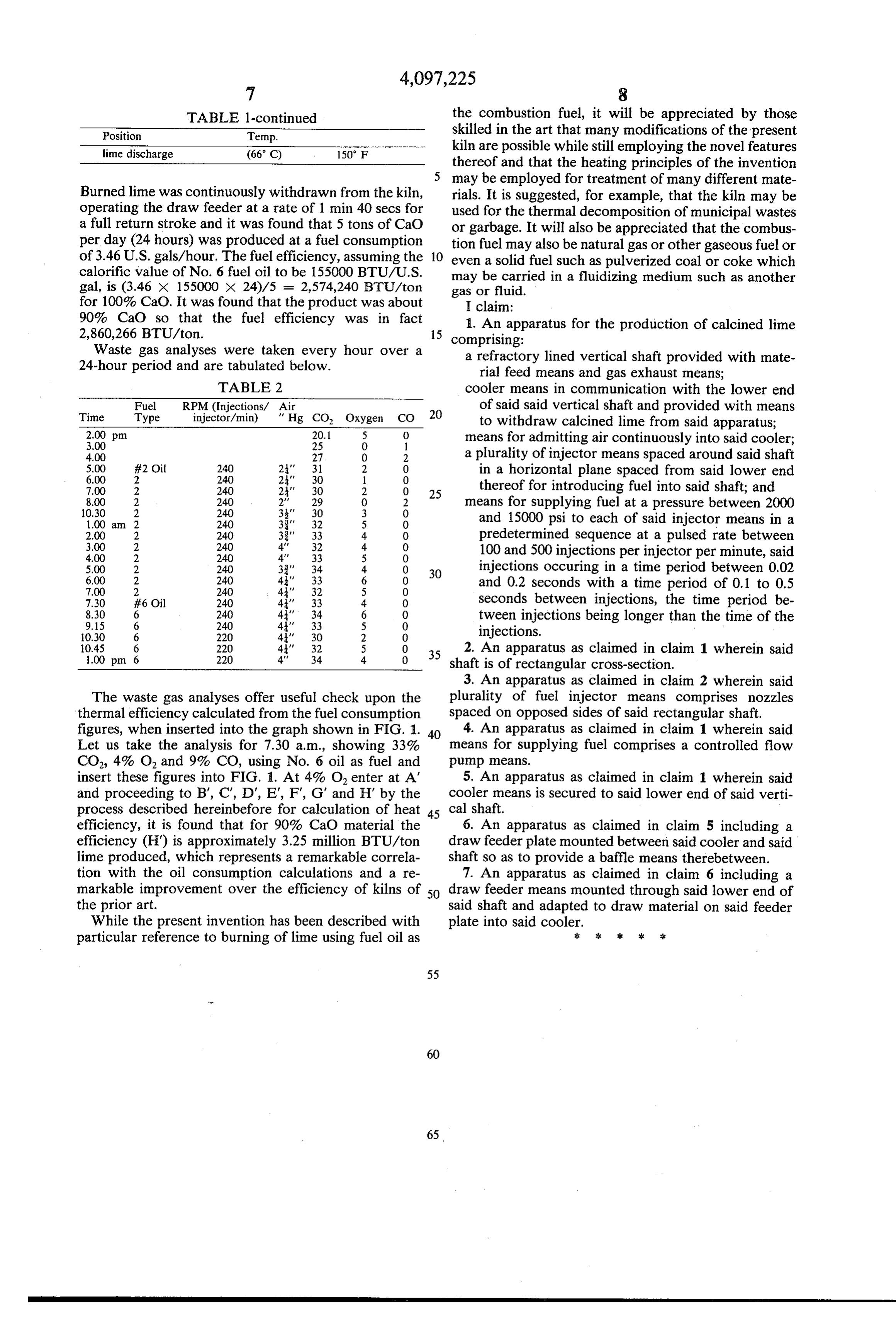
Waste gas analyses were taken every hour over a a refractory lined vertical shaft provided with mate 24-hour period and are tabulated below. rial feed means and gas exhaust means; TABLE 2 cooler means in communication with the lower end
Time
Fuel
Type
RPM (Injections/ Air injector/min) " Hg CO, Oxygen CO 20 of said said vertical shaft and provided with means to withdraw calcined lime from said apparatus;
means for admitting air continuously into said cooler;
4.00 27 O 2 a plurality of injector means spaced around said shaft
#2 Oil
in a horizontal plane spaced from said lower end 7.00 2 240 2' 30 2 O 25 thereof for introducing fuel into said shaft; and
means for supplying fuel at a pressure between 2000 1.00 am 2 240 33' 32 5 O and 15000 psi to each of said injector means in a 2.00 2 240 33' 33 4 0 predetermined sequence at a pulsed rate between 3.00 2 240 4' 32 4 0 100 and 500 injections per injector per minute, said
5.00 2 240 33' 34 4 O 3O injections occuring in a time period between 0.02 6.00 2 240 4' 33 6 O and 0.2 seconds with a time period of 0.1 to 0.5
7.30 #6 Oil 240 4' 33 4 0 seconds between injections, the time period be
tween injections being longer than the time of the 0.30 6 220 44' 30 2 0. injections.
O 35 2. An apparatus as claimed in claim 1 wherein said shaft is of rectangular cross-section.
3. An apparatus as claimed in claim 2 wherein said
The waste gas analyses offer useful check upon the plurality of fuel injector means comprises nozzles thermal efficiency calculated from the fuel consumption spaced on opposed sides of said rectangular shaft. figures, when inserted into the graph shown in FIG. 1. 40 4. An apparatus as claimed in claim 1 wherein said Let us take the analysis for 7.30 a.m., showing 33% means for supplying fuel comprises a controlled flow CO, 4% O, and 9% CO, using No. 6 oil as fuel and pump means.
insert these figures into FIG. 1. At 4% O. enter at A' 5. An apparatus as claimed in claim 1 wherein said and proceeding to B", C", D', E, F, G' and H' by the cooler means is secured to said lower end of said verti process described hereinbefore for calculation of heat 45 cal shaft.
efficiency, it is found that for 90% CaO material the 6. An apparatus as claimed in claim 5 including a efficiency (H") is approximately 3.25 million BTU/ton draw feeder plate mounted between said cooler and said lime produced, which represents a remarkable correla shaft so as to provide a baffle means therebetween. tion with the oil consumption calculations and a re 7. An apparatus as claimed in claim 6 including a markable improvement over the efficiency of kilns of 50 draw feeder means mounted through said lower end of the prior art. said shaft and adapted to draw material on said feeder While the present invention has been described with plate into said cooler.: 2. : x: ck particular reference to burning of lime using fuel oil as
Provenance
- Collection
- Cited prior art
- Original PDF
- patentimages.storage.googleapis.com →
- Filed
- 1977-01-17
- Pages
- 9
- Method
- pdftotext (the PDF's own text layer) + pdftoppm 300dpi page scans
- Source
- Google Patents bibliographic record
- Granted
- 1978-06-27
- Inventors
- Terence Arthur Rourke
- Transcribed from
- patentimages.storage.googleapis.com →