patent · US4747773
Shaft kiln utilized for lime production
31 May 1988
Page 1 — bibliographic record
United States Patent (19) 11 Patent Number: 4,747,773 Predescu et al. (45) Date of Patent: May 31, 1988
(54) SHAFT KILN UTILIZED FOR LIME
PRODUCTION
4,351,119 9/1982 Meunier ................................ 432/96
Primary Examiner-Henry C. Yuen 76) Inventors: Lucian A. Predescu; Lucian D. Attorney, Agent, or Firm-Jennings, Carter, Thompson Predescu, both of 3931. Somerset Pl, & Veal
Tuscaloosa, Ala. 35405 57 ABSTRACT 21 Appl. No.: 59,332 A vertical shaft kiln utilized in calcining limestone de 22 Filed: Jun. 8, 1987 fines a series of processing zones including an upper preheating Zone, a first calcining zone, a second calcin
Related U.S. Application Data ing zone having a length twice that of the first calcining Zone and a material cooling zone, Burners inject burnt 63 Continuation of Ser. No. 842,234, Mar. 21, 1986. gases intermediate the two calcining zones. Major heat 51 Int. Cl* ......................... F27B 15/00; F27D 1/08 transfer to the limestone is accomplished in the first (52) U.S. C. ........................................ 432/14; 432/95; calcining Zone by directing a major portion of the burnt 432/96; 432/99; 432/101 gases in counter-current to the material flow there 58) Field of Search ................................... 432/95-101 through. Minor heat transfer is accomplished in the second calcining Zone by directing a minor portion of (56) References Cited the burnt gases therethrough in co-current relation with
2,788,961 4/1957 Pooley et al. ....................... 432/101 in the material cooling zones and mixed with the minor 3,142,480 7/1964 Azbe ..... ... 432/99 portion of burnt gases externally of the shaft prior to 3,285,590 1 1/1966 Parsons . ... 432/99 injection into the burners.
3,544,090 12/1970 Peeters ...... ... 432/95 3,887,326 6/1975 Townley ............................... 432/99 2 Claims, 2 Drawing Sheets
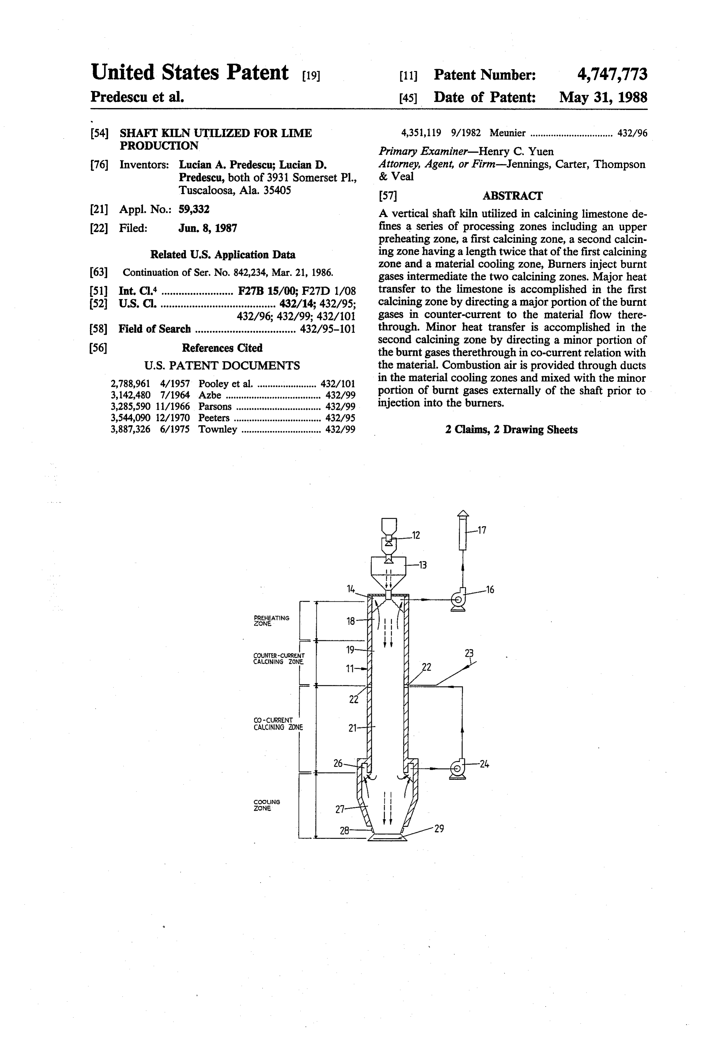
PREHEAmg
Zone
CANNs ZONE
CACNNG ZONE
Page 2
Drawing sheet — no readable text.
Page 3
Drawing sheet — no readable text.
Page 4
and mixed with the fresh air withdrawn from the cool
SHAFT KLN UT LIZED FOR LIME ing zone for recirculation to the burners. The remaining PRODUCTION major portion of the hot gases are withdrawn upwardly through the first calcining zone to a collector which
This is a continuation in part of Ser. No. 842,234 filed removes them from the kiln. The upper calcining zone Mar. 21, 1986. is about one-half the length of the lower calcining zone; FIELD OF INVENTION therefore, the limestone is subjected to the major flow of hot gases and consequently the major portion of the
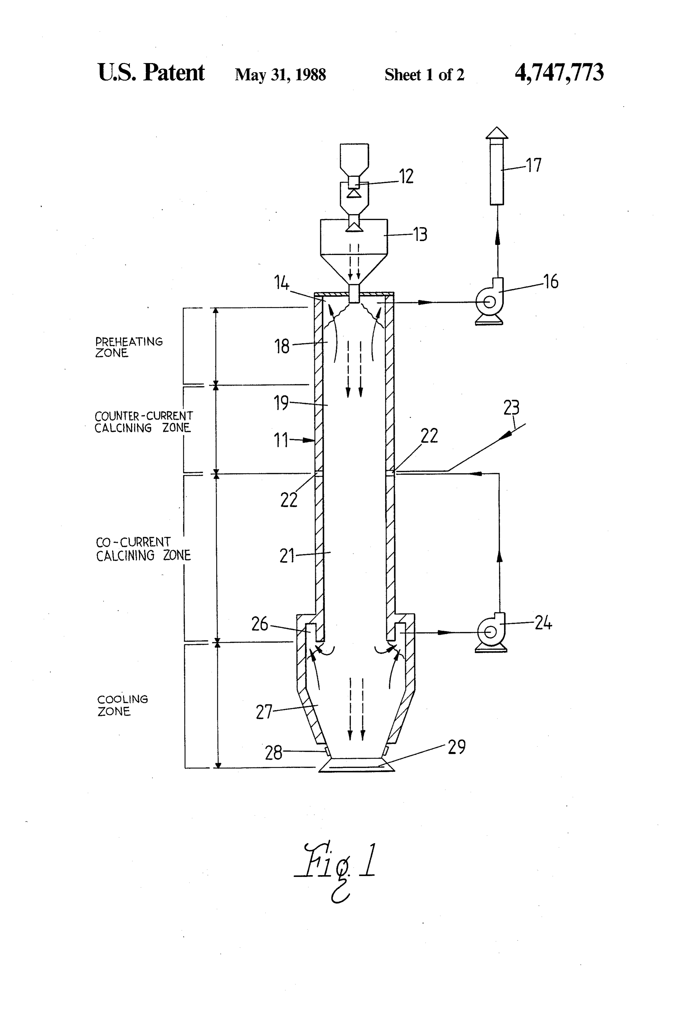
The present invention relates generally to kilns and in heat for only one third of the time it is in transit. The particular to kilns used in the processing of limestone. O remainder of the transit time is in the second calcining More particularly the invention may be characterized as zone where less heat is available for transfer to the a vertical shaft kiln and process wherein limestone is limestone; thus, the product is not burned. subjected to an optimal heat regime during the process BRIEF DESCRIPTION OF THE DRAWINGS ing thereof. In even greater particularity the present invention may be described as a method and apparatus 15 Apparatus embodying features of my invention and for processing limestone wherein the heat transfer be which may be utilized in my process are depicted in the tween the kiln and the limestone is controlled in distinct accompanying Figures which form a portion of this OS application and wherein:
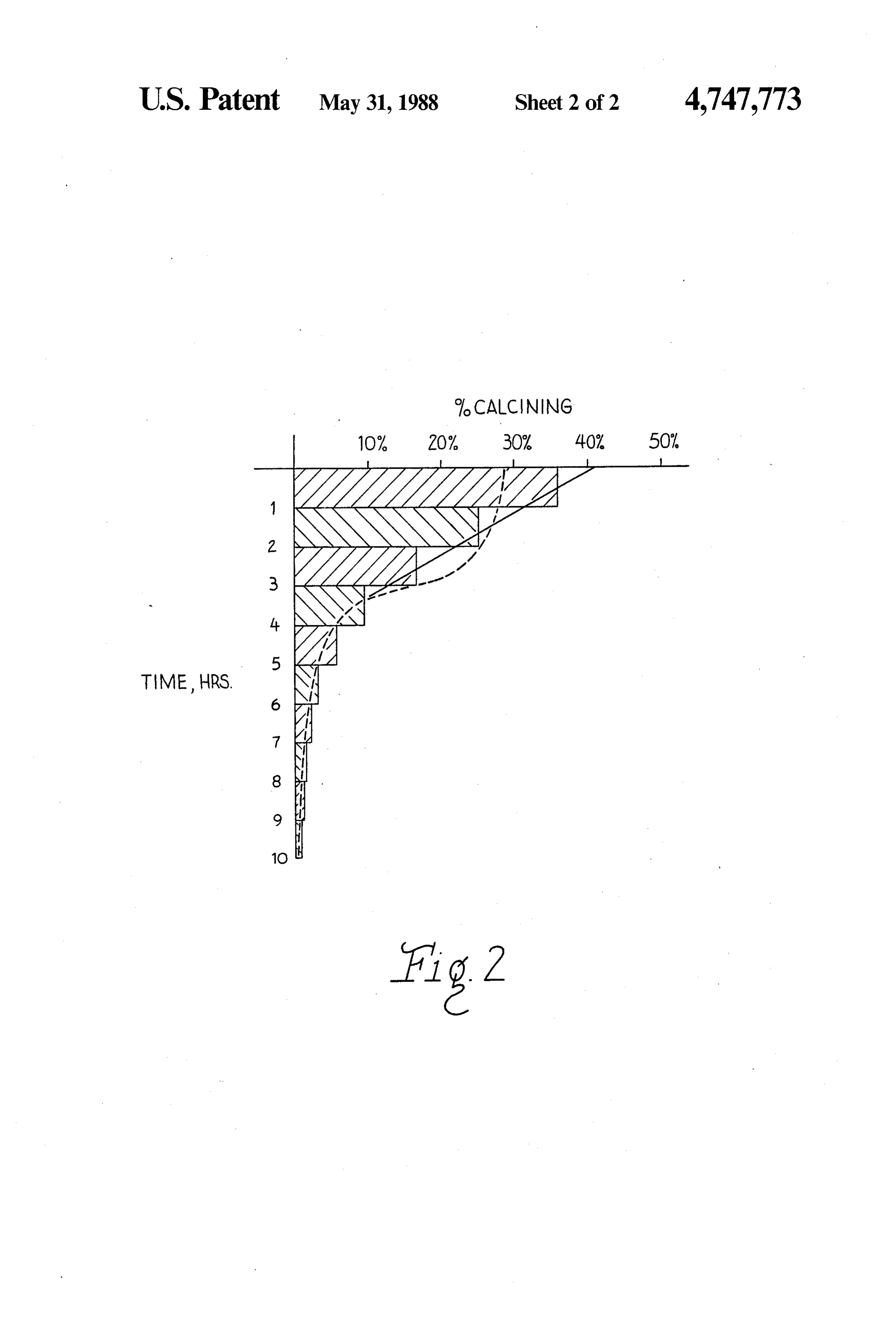
BACKGROUND OF THE INVENTION FIG. 1 is a schematic representation of my kiln; and 20 FIG. 2 is a graph of the optimal heating curve.
The utilization of shaft kilns and rotary kilns for the DESCRIPTION OF A PREFERRED production of limestone is well known. The rotary kiln EMBODIMENT produces a higher quality limestone but has a high spe cific consumption of fuel and/or electricity and a high As may be seen in FIG. 1 my apparatus is essentially initial investment. Shaft kilns which are known to us 25 a vertical hollow shaft kiln shown generally as 11. Atop produce lime of a low quality yet have a high consump the kiln 11 is an air tight charging device 12, and bunk tion of fuel and/or electricity. Furthermore, such kilns er-buffer 13 for limestone received from the charging have a low rate of production and can only use large device 12. Immediately below the bunker-buffer 13 is an grain limestone. Introduction of small grain limestone, exhaust collector channel 14 for evacuating burn gases that is limestone having an average diameter below a 30 from the kiln 11. This collector channel 14 is in commu particular size, into conventional shaft kilns results in nication with a fan 16 which is controlled to withdraw the small grain limestone being burned and the quality gases from the kiln 11 at a selected rate and exhausts the of the product suffers further degradation. same through stack 17. Immediately beneath the bunk SUMMARY OF THE INVENTION er-buffer 13 is a preheating zone 18 through which 35 limestone from the bunker-buffer 13 descends. Subja
It is the object of the present invention to provide a cent the preheating zone 18 is a first calcining zone 19 shaft kiln which produces a high quality lime product which has a predetermined length, L. A second calcin and which can process small grain limestone through ing zone 21 having a length of approximately 2L is the use of an optimal temperature regime. located beneath the first calcining zone 19. A plurality It is another object of the invention to provide an 40 of burners 22 are located intermediate the first and sec economical kiln for the production of limestone of a ond calcining zones and inject burnt gases into the kiln very simple construction. 11. The gases are the result of combustion of a fuel Yet another object is to provide a shaft kiln with a supplied through conduits 23 in the presence of a mix high production rate and a low consumption of fuel ture of gases supplied to the burners 22 from a recircula and/or electricity. 45 tion fan 24. The recirculation fan 24 draws these gases A still further object of the invention is to provide a from a collector channel 26 located below the second kiln wherein conventional fans that can be used to cir calcining zone and above a material cooling zone 27. culate and remove the hot gases. The material cooling zone has a plurality of adjustable These and other objects of our invention are accom apertures or ducts 28 about the bottom thereof through plished through my novel structure and processes for 50 which fresh air or combustion gas may be admitted to utilizing this structure. Our structure is an upstanding the kiln 11. A discharging device 29 below the cooling hollow shaft kiln which is divided into a plurality of zone permits removal of the product from the kiln. It Zones including an upper preheating zone, a first calcin should be noted that air is admitted to the kiln 11 only ing Zone, a second calcining Zone, and a materials cool through the ducts 28.
ing zone. Limestone is introduced to the kiln via an air 55 To appreciate the utility of our invention it should be tight charging means at the top of the preheating zone. remembered that the calcining process is an endother A plurality of adjustable ducts are provided at the mate mic reaction wherein heat is absorbed by the limestone rial cooling zone to introduce fresh air to the kiln. The and as long as CO2 is evolved, the lime cannot be burnt. fresh air is drawn upwards in counter current with the This process starts at the surface of the limestone and material through the material cooling zone to a collec proceeds to the core and under optimal conditions pro tor channel which is in communication with a fan which ceeds at a rate which allows complete calcining of the withdraws the fresh air irom the shaft of the kiln and limestone without overburning. lt should also be re passes it to a set of burners located intermediate the first membered that the primary heat transport mechanism and second calcining zone. The burners inject hot gases used is the hot burnt gases injected by the burners 22. resulting from the combustion of a fuel into the kiln. A 65 Note that to calcine the limestone at a constant rate minor portion of these hot gases are drawn down toward the center of each grain a greater quantity of wardly through the second calcining zone to the collec heat must be transferred to the limestone per unit of tor channel where they are withdrawn from the shaft radial measure at the beginning of the process than at
Page 5
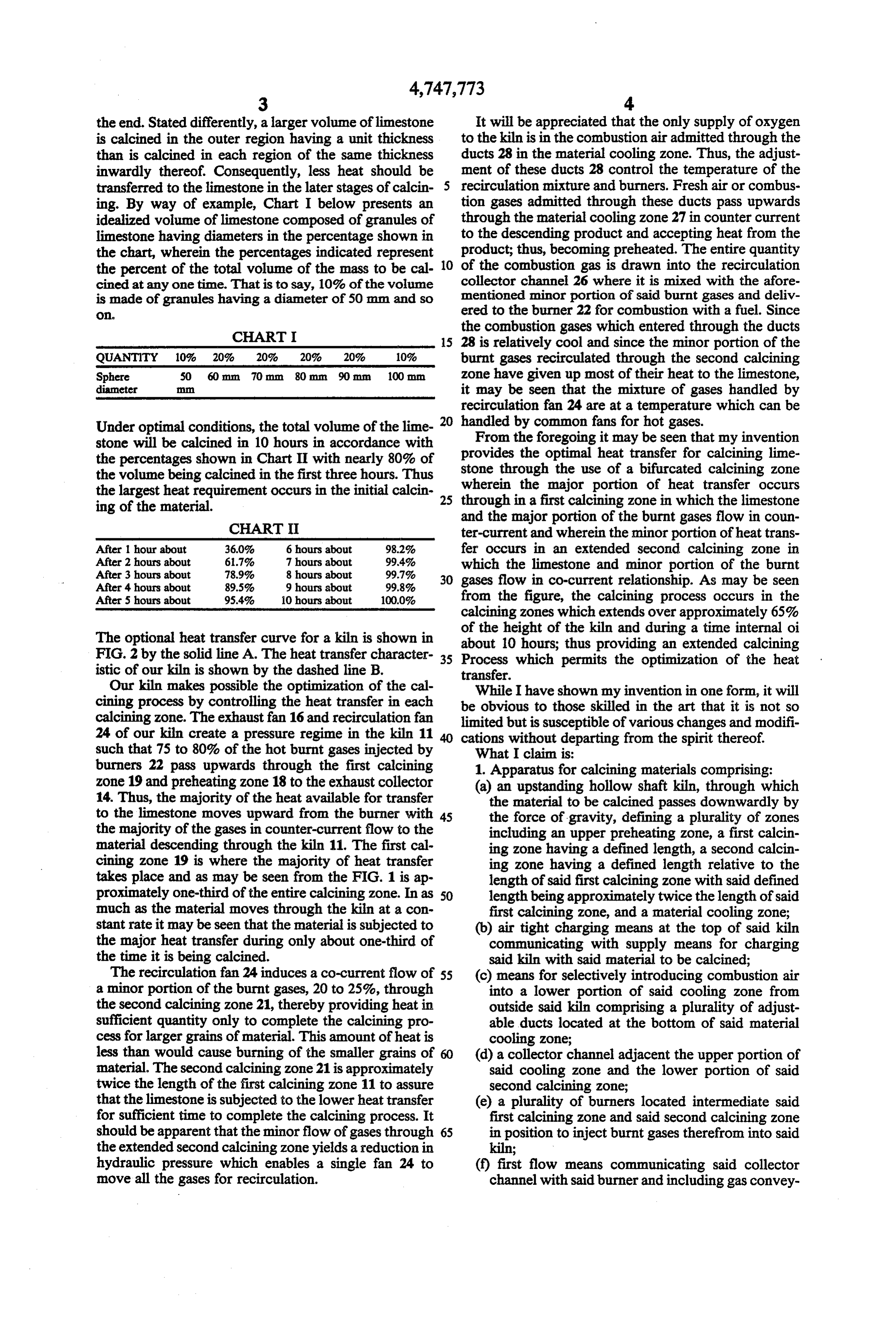
the end. Stated differently, a larger volume of limestone It will be appreciated that the only supply of oxygen is calcined in the outer region having a unit thickness to the kiln is in the combustion air admitted through the than is calcined in each region of the same thickness ducts 28 in the material cooling zone. Thus, the adjust inwardly thereof. Consequently, less heat should be ment of these ducts 28 control the temperature of the transferred to the limestone in the later stages of calcin- 5 recirculation mixture and burners. Fresh air or combus ing. By way of example, Chart I below presents an tion gases admitted through these ducts pass upwards idealized volume of limestone composed of granules of through the material cooling zone 27 in counter current limestone having diameters in the percentage shown in to the descending product and accepting heat from the the chart, wherein the percentages indicated represent product; thus, becoming preheated. The entire quantity the percent of the total volume of the mass to be cal- 10 of the combustion gas is drawn into the recirculation collector channel 26 where it is mixed with the afore cined at any one time. That is to say, 10% of the volume is made of granules having a diameter of 50 mm and so mentioned minor portion of said burnt gases and deliv O ered to the burner 22 for combustion with a fuel. Since
CHART
the combustion gases which entered through the ducts 15 28 is relatively cool and since the minor portion of the
QUANTITY 10% 20%. 20% 20%. 20% burnt gases recirculated through the second calcining
Sphere 50 60 mm 70 mm 80 mm 90 mm zone have given up most of their heat to the limestone,
diameter it may be seen that the mixture of gases handled by recirculation fan 24 are at a temperature which can be
Under optimal conditions, the total volume of the lime- 2O handled by common fans for hot gases. From the foregoing it may be seen that my invention stone will be calcined in 10 hours in accordance with the percentages shown in Chart II with nearly 80% of stone provides the optimal heat transfer for calcining lime the volume being calcined in the first three hours. Thus wherein through the use of a bifurcated calcining zone the largest heat requirement occurs in the initial calcin through inthea first major portion of heat transfer occurs calcining zone in which the limestone
CHART II
and the major portion of the burnt gases flow in coun ter-current and wherein the minor portion of heat trans
After 1 hour about 36.0% 6 hours about 98.2% fer occurs in an extended second calcining zone in After 2 hours about 6.7% 7 hours about 99.4% which the limestone and minor portion of the burnt After 3 hours about 78.9% 8 hours about 99.7%
After 4 hours about 89.5% 9 hours about 99.8% gases flow in co-current relationship. As may be seen After 5 hours about 95.4% 10 hours about 100.0% from the figure, the calcining process occurs in the calcining zones which extends over approximately 65%
The optional heat transfer curve for a kiln is shown in of the height of the kiln and during a time internal oi about 10 hours; thus providing an extended calcining
FIG. 2 by the solid line A. The heat transfer character Process which permits the optimization of the heat istic of our kiln is shown by the dashed line B. transfer.
Our kiln makes possible the optimization of the cal cining process by controlling the heat transfer in each beWhile I have shown my invention in one form, it will obvious to those skilled in the art that it is not so calcining zone. The exhaust fan 16 and recirculation fan limited but is susceptible of various changes and modifi 24 of our kiln create a pressure regime in the kiln 11 cations without departing from the spirit thereof. such that 75 to 80% of the hot burnt gases injected by What I claim is:
burners 22 pass upwards through the first calcining 1. Apparatus for calcining materials comprising: zone 19 and preheating zone 18 to the exhaust collector (a) an upstanding hollow shaft kiln, through which 14. Thus, the majority of the heat available for transfer the material to be calcined passes downwardly by to the limestone moves upward from the burner with 45 the force of gravity, defining a plurality of zones the majority of the gases in counter-current flow to the including an upper preheating Zone, a first calcin material descending through the kiln 11. The first cal ing zone having a defined length, a second calcin cining zone 19 is where the majority of heat transfer ing zone having a defined length relative to the takes place and as may be seen from the FIG. 1 is ap length of said first calcining zone with said defined proximately one-third of the entire calcining zone. In as SO length being approximately twice the length of said much as the material moves through the kiln at a con first calcining zone, and a material cooling zone; stant rate it may be seen that the material is subjected to (b) air tight charging means at the top of said kiln the major heat transfer during only about one-third of communicating with supply means for charging the time it is being calcined. said kiln with said material to be calcined; The recirculation fan 24 induces a co-current flow of 55 (c) means for selectively introducing combustion air a minor portion of the burnt gases, 20 to 25%, through into a lower portion of said cooling zone from the second calcining zone 21, thereby providing heat in outside said kiln comprising a plurality of adjust sufficient quantity only to complete the calcining pro able ducts located at the bottom of said material cess for larger grains of material. This amount of heat is cooling zone;
less than would cause burning of the smaller grains of 60 (d) a collector channel adjacent the upper portion of material. The second calcining zone 21 is approximately said cooling zone and the lower portion of said twice the length of the first calcining zone 11 to assure second calcining zone;
that the limestone is subjected to the lower heat transfer (e) a plurality of burners located intermediate said for sufficient time to complete the calcining process. It first calcining zone and said second calcining zone should be apparent that the minor flow of gases through 65 in position to inject burnt gases therefrom into said the extended second calcining zone yields a reduction in kiln;
hydraulic pressure which enables a single fan 24 to (f) first flow means communicating said collector move all the gases for recirculation. channel with said burner and including gas convey
Page 6
ing means for conveying gases from said collector (b) selectively introducing combustion air to said kiln channel to said burners and creating a negative through the lower end of said material cooling pressure within said collector channel to convey a Zone;
minor portion of said burnt gases injected into said (c) injecting burnt gases resulting from the combus kiln downwardly through said second calcining 5 tion of a fuel and said combustion air into said kiln zone in co-current flow with said material to said intermediate said first calcining zone and said sec collector channel for intermingling with said com ond calcining zone;
bustion air and recycling to said burners, said (d) subjecting said material to be calcined succes sively during downward movement thereof minor portion comprising about 20 to 25% of the 10 through said zones to a counter-current flow of a burnt gases injected to the kiln from said burner; major portion of said burnt gases in said upper and preheating Zone and said first calcining zone, a a (g) second flow means communicating with an upper co-current flow of a minor portion of said burnt portion of said preheating zone for exhausting gases in said second calcining zone, said minor burnt gases therefrom and creating a negative pres 15 portion comprising about 20 to 25% of the burnt sure within said upper portion of said preheating gases injected into said kiln, and a counter-current zone to convey a major portion of said burnt gases flow of said combustion air in said material cooling injected into said kiln upwardly through said first zone;
calcining zone and said preheating zone in counter 20 (e) withdrawing substantially the entire quantity of current flow to said material. combustion air introduced into said material cool 2. A process for calcining materials comprising the ing zone and subbstanially the entire quantity of steps of: said minor portion of said burnt gases and said combustion air from said kiln shaft intermediate (a) introducing material to be calcined at the upper said second calcining zone and said matcrial cool end of a hollow shaft kiln through which said mate 25 ing zone and utilizing the mixture thereof for said rial passes downwardly by the force of gravity combustion of a fuel;
through a plurality of zones in series including an (f) removing said major portion of the burnt gases upper pre-heating zone, a first calcining zone, a from said upper part of said kiln; and second calcining zone having a length approxi (g) discharging the calcined product at the lower end mately twice that of said first calcining zone, and a 30 of said material kcooling
zone.
material cooling zone;
Provenance
- Collection
- Cited prior art
- Original PDF
- patentimages.storage.googleapis.com →
- Filed
- 1987-06-08
- Pages
- 6
- Method
- pdftotext (the PDF's own text layer) + pdftoppm 300dpi page scans
- Source
- Google Patents bibliographic record
- Granted
- 1988-05-31
- Inventors
- Lucian A. Predescu; Lucian D. Predescu
- Transcribed from
- patentimages.storage.googleapis.com →