patent · US5460517
Shaft kiln for burning a lumpy mineral charge
24 October 1995
Page 1 — bibliographic record
United States Patent (19) 11 Patent Number: 5,460,517 Scheibenreif et al. (45) Date of Patent: Oct. 24, 1995
54 SHAFT KILN FOR BURNING A LUMPY, 4,747,773 5/1988 Predescu et al. ......................... 432/99 MNERAL CHARGE 4,797,092 l/1989 Pieper ....................................... 432/95 4,881,869 11/1989 Henneken et al. ........................ 432/98 75 Inventors: Karl Scheibenreif, Kloten, Jiri Pacak,
Langnau am Albis, both of Switzerland Primary Examiner-Raymond A. Nelli
Attorney, Agent, or Firm-Ladas & Parry 73 Assignee: Maerz-Ofenbau AG, Zurich,
Switzerland (57) ABSTRACT
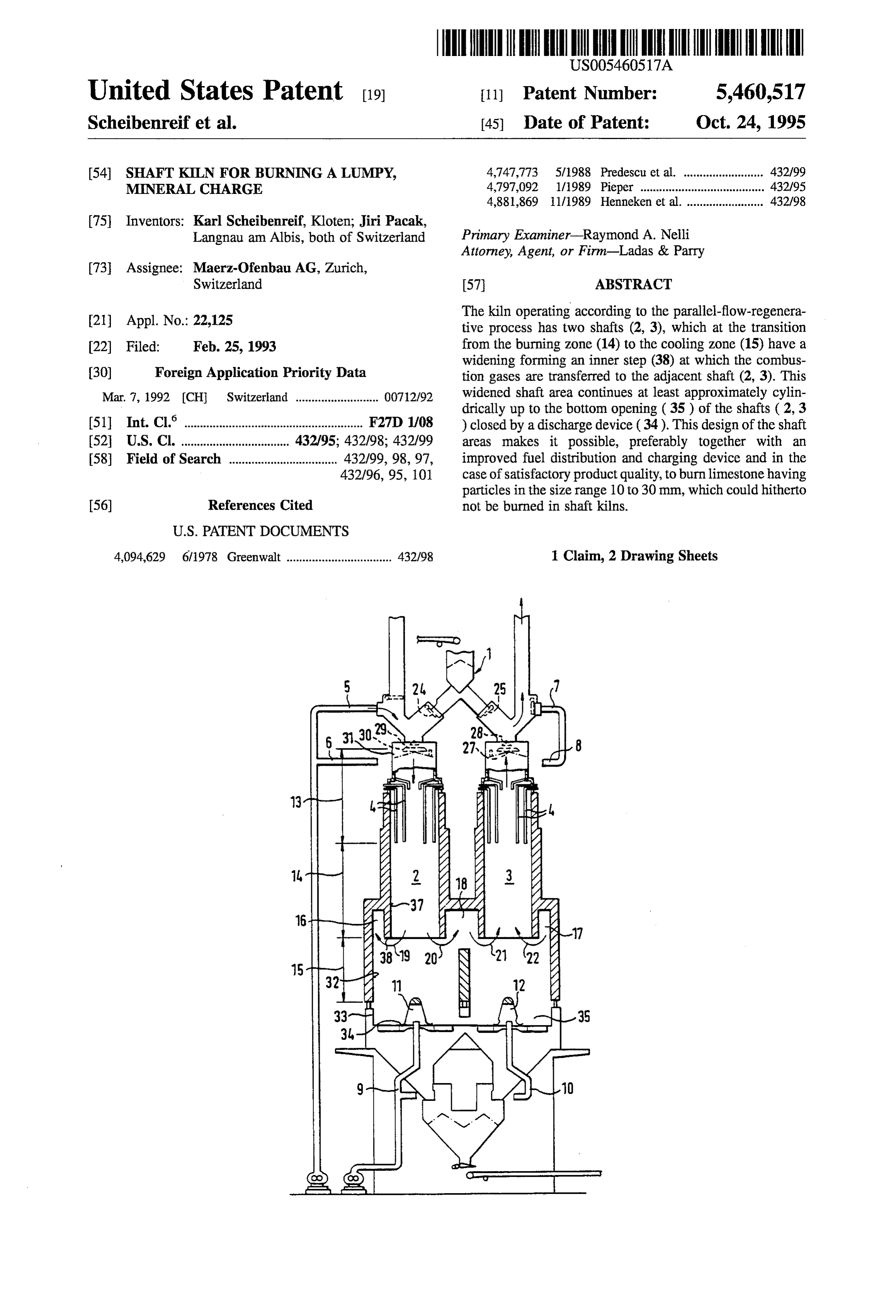
The kiln operating according to the parallel-flow-regenera 21 Appl. No.: 22,125 tive process has two shafts (2, 3), which at the transition 22 Filed: Feb. 25, 1993 from the burning zone (14) to the cooling zone (15) have a widening forming an inner step (38) at which the combus (30) Foreign Application Priority Data tion gases are transferred to the adjacent shaft (2, 3). This Mar. 7, 1992 (CH Switzerland .......................... O072/92 widened shaft area continues at least approximately cylin drically up to the bottom opening (35) of the shafts (2, 3 (51] Int. Cl. ...................................... F27D 1/08 ) closed by a discharge device (34). This design of the shaft 52 U.S. Cl. ............. 432/95; 432/98; 432/99 areas makes it possible, preferably together with an 58 Field of Search .................................. 432/99, 98, 97, improved fuel distribution and charging device and in the 432/96, 95, 101 case of satisfactory product quality, to burn limestone having particles in the size range 10 to 30 mm, which could hitherto 56) References Cited not be burned in shaft kilns.
4,094,629 6/1978 Greenwalt ................................. 432/98 1 Claim, 2 Drawing Sheets
Page 2
Drawing sheet — no readable text.
Page 3
Drawing sheet — no readable text.
Page 4
SHAFT KILN FOR BURNING ALUMPY, As a result of the only small, step-free slope or lack of MNERAL CHARGE slope of the shaft wall in the cooling zone up to the outlet edge of the bottom opening, it is ensured that granular
BACKGROUND OF THE INVENTION material does not grow on the shaft wall and constrict the combustion gas flow path. The considerable kiln efficiency
The invention relates to a shaftkiln for burning a mineral drop, which can lead to shaft kiln failure occurring in the charge, particularly small-sized limestone, in a parallel case of shaft kilns of the aforementioned, known type as a flow-regenerative process, with at least two circular cylin result of the clogging of the flow path is prevented in this drical shafts, each of which has a preheating Zone, a burning way.
zone and a cooling zone and which are interconnected in the 10 As a result of the larger particle size distribution range in transition area between the burning zone and the cooling the kiln, it is recommended that finer and coarser particulate Zone by a connecting passage for combustion gases flowing material be supplied to the kiln in radially different areas. in periodically alternating directions, the shafts being sur For this purpose it is particularly appropriate to use e.g. a rounded by a common passage connected to the shaft areas, charging device as known from CH-A-678847. so that at the transition to the adjacent shaft, said passage 15 For a better distribution of the heat supply and therefore forms the connecting passage. for a uniform product quality, it is recommended that a A shaft kiln of this type corresponds to the known narrower arrangement and a larger number of lances are MAERZ construction. The circular cross-section of his provided for the supply of a liquid or gaseous fuel. shafts is necessary for an adequately uniform heat distribu 20 tion over the shaft cross-section, if the kiln is to be suitable BRIEF DESCRIPTION OF THE DRAWINGS for larger throughput capacities, as cannot be achieved in the case of rectangular shaft cross-sections. There is also a good The invention is described in greater detail hereinafter heat distribution of the joint, surrounding passage, in that it relative to a non-limitative embodiment and the attached permits a uniform drawing off of combustion gases from the 25 drawings, wherein show:
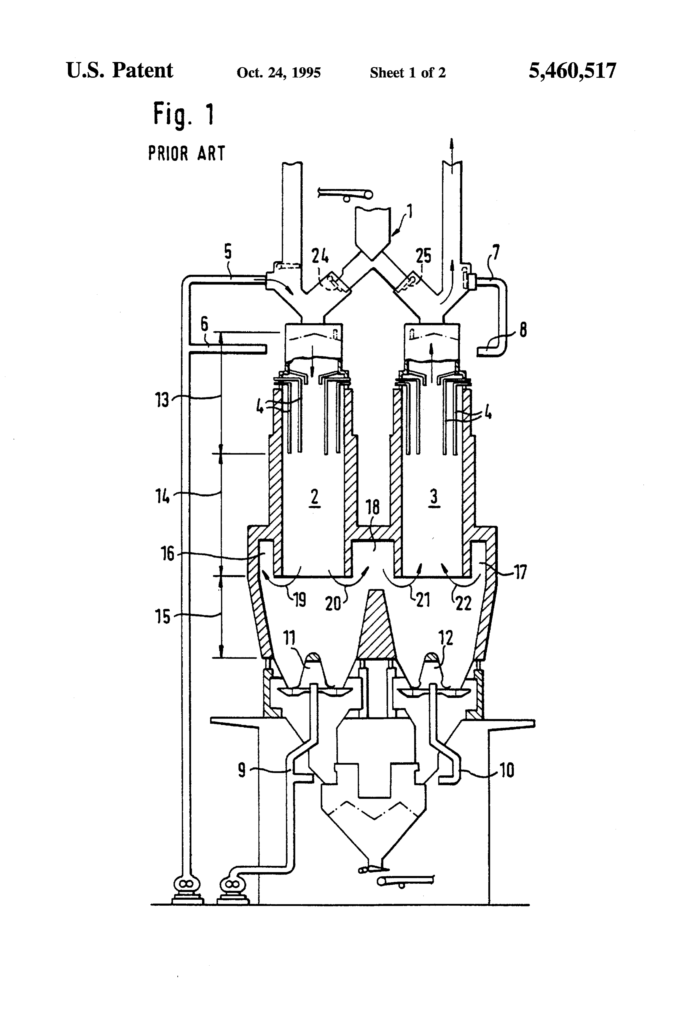
burning zone of one shaft and a uniform supply thereof to FIG. 1 A diagrammatic sectional representation of a the adjacent shaft. However, it make it necessary to increase known kiln.
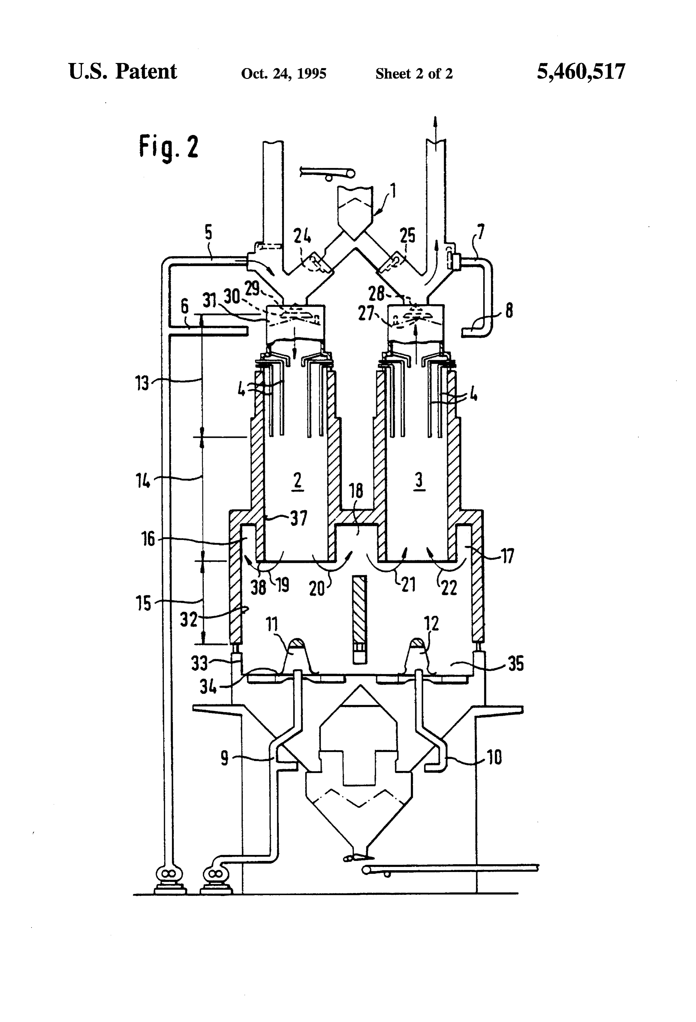
the diameter of the shaft area in the upper region of the FIG. 2A simplified, part sectional representation of a kiln cooling zone compared with the diameter of the part of the according to the invention.
shaft area of the cooling zone located above it. Thus, there is an increased conical taper in the direction of the shaft 30 DETAILED DESCRIPTION OF THE bottom opening, which is of a conventional nature for shaft PREFERRED EMBODIMENT outlets, silo outlets, etc.
For a uniform heat distribution and for preventing a FIG. 1 shows a parallel-flow-regenerative lime kiln in clogging or blocking up in the vicinity of the passages, it is 35 accordance with the Applicant's brochure. Large numbers of also necessary to downwardly limit the lump size of the such kilns are manufactured and are known to the Expert as material to be burnt, so that to obtain a satisfactory quality MAERZ kins.
of the burned product it is recommended that the lump size As also in the case of the kiln according to the invention distribution be in the range 30 to 150 mm. Material with a and FIG. 2, the charge alternately supplied to the shafts 2, 3 small particle size of less than 30 mm must be separated and by means of the charging device 2 is simultaneously burned processed in some other way, e.g. in a more complicated 40 in both shafts 2,3. In intervals of 12 to 15 minutes only one rotary kiln operating with a lower thermal efficiency. DE shaft is heated, in that the fuel supply by means of the lances A-1 252 850 admittedly already proposes a shaft kiln 4 and the feeding in of combustion airby means of the pipes suitable for burning a material with a minimum particle size 5 to 8 take place in a corresponding periodic manner to only of 10 mm, but it is then necessary to accept constructional 45 a single shaft 2 or 3. Cooling air is continuously supplied disadvantages, which prevented the practical realization of from below to the shafts 2, 3 by means of the lines 9, 10 and such a kiln. a central distributing cone 11, 12. Therefore for the charge the shafts have an upper preheating zone 13, a central
SUMMARY OF THE INVENTION
burning zone 14 and a lower cooling zone 15.
50 The combustion gases flow out of the combustion zone 14
The problem of the invention is to find a kiln of the into an annular passage surrounding the particular shaft 2, 3 aforementioned type which, unlike in the case of known and a connection 18 between the two annular passages 16, shaftkilns, is also suitable without any decrease in efficiency 17 permits an overflow to the annular passage 17, 16 of the and significant quality deterioration with respect to the burnt adjacent shaft 3, 2. The arrows 19-22 indicate the flow product, for processing a charge with a much smaller lump 55 direction, during the heating of the left-hand shaft 2 and size, e.g. in the range 10 to 30 mm, so that there is no need during the preheating in the right-hand shaft 3 of the charge for processing in rotary kilns. by means of the combustion gases flowing upwards therein. According to the invention this problem is solved in that The charging of the kiln shafts 2, 3 preferably also takes the shaft interior in the vicinity of the cooling zone and place in alternating manner during the switching over of the following onto the surrounding passage extends downwards 60 heating, in that the corresponding flap 24 or 25 of the with an at least approximately constant cross-section to a charging device 1 is opened.
bottom shaft opening closed by a discharge device. For an advantageous distribution between coarser and Although the solution according to the invention requires finer charge, in the embodiment of a kiln according to the a larger size of the lower furnace area and the discharge invention shown in FIG. 2 below the charging device 1 and device, this extra expenditure is soon made good by the 65 within the shaft 2, 3 is provided a split distributing cone 27, relatively large throughput capacity of such shaft kilns and which fills a significant part of the shaft cross-section. The the relatively low energy consumption thereof. upper or radial central part 28 of the distributing cone 27 can
Page 5
be pivoted away to the side. In the pivoted away position of according to the invention, as a result of the novel design of the adjustable cone part 28 the always centrally charged the interior of the shafts in the vicinity of the cooling Zone charge passes through the central opening 29 of the lower 15 a clogging of the flow cross-section and an efficiency cone part 30 into the central region of the shaft 2, 3, whilst decrease, even when using a charge with a particle size of 10 in the case of a central position of the upper cone part 28 to 30 mm, is reliably avoided. This also makes it possible to over the central opening 29, the charge slides radially use the advantageous overall shaft kiln design for the outwards over the two cone parts 28, 30 and consequently processing of stone material, which has hitherto had to be the gap 31 between the distributing cone 27 and the shaft disposed of on waste heaps or burnt in a very expensive wall into the peripheral shaft area. There is subsequently an improved thorough mixing during the slow sinking of the 10 manner in rotary kilns.
What is claimed is:
charge through the burning Zone of the shaft 2, 3. 1. A shaft kiln for burning a mineral charge, particularly The diameter of the shafts 2, 3 in the burning zone is e.g. small-sized limestone in a parallel-flow-regenerative pro
cess with at least two circular cylindrical shafts (2.3), each
As can be seen from a comparison of FIGS. 1 and 2, of which has a pre-heating zone (13), a burning Zone (14) unlike in the case of the known kiln, the kiln according to the 15 and a cooling Zone (15) and which are interconnected in the invention has shafts 2, 3, whose inner wall face 32 in the transition area between the burning zone (14) and the vicinity of the cooling zone 15 is vertical and therefore cooling Zone (15) by a connecting passage (18) for com circular cylindrical to the edge 33 of the bottom opening 35 bustion gases flowing in periodically alternating direction, closed by the discharge table 34. AT the start of the cooling the shaft (2.3) being surrounded by a common passage Zone 15 the wall face 32, which is cylindrical or inclined 20 (16,17) connected to the shafts, so that at the transition of inwards by less than 4, is outwardly displaced with respect adjacent shafts (2.3) the common passage forms the inter to the inner face 37 of the shaft 2, 3 in the vicinity of the connecting passage (18), a charging device (1) being pro burning zone 14 to a larger diameter, so that there is an inner vided having a distributing device (27.31) for the separatic step 38. The latter is flowed round in hairpin-like manner at 25 charging of a finer and coarser charge material to radially very high temperatures by the combustion gases on their different shaft areas, wherein the shaft interior in the vicinity journey into the annular passage 16 and in the direction of the cooling zone (15) and following onto the surrounding indicated by the arrows 19, 20. passage (16,17) extends downward with an at least approxi In said region of the flow path of the combustion gases or mately constant cross-section to a bottom shaft opening (35) in the region of the flow into the annular passage 16, a 30 closed by a discharge device (34), the shaft interior in the clogging of the shaft cross-section, particularly caused by vicinity of the cooling zone (15) extends in circular cylin the finer-grained charge, would be particularly disadvanta drical manner to the bottom shaft opening (35), and, at thc geous, because in this region there is in any case a constric transition region from the burning zone (14) to the cooling tion of the combustion gas flow path. The clogging or zone (15), the shafts (2.3) are widened downwardly by blocking up of the necessary flow cross-sections in known 35 means of a step to a cylindrical shaft. shaft kilns can lead to a drop to Zero of the kiln efficiency or to the complete failure of the kiln. In the case of a shaft kiln
Provenance
- Collection
- Cited prior art
- Original PDF
- patentimages.storage.googleapis.com →
- Filed
- 1993-02-25
- Pages
- 5
- Method
- pdftotext (the PDF's own text layer) + pdftoppm 300dpi page scans
- Source
- Google Patents bibliographic record
- Granted
- 1995-10-24
- Inventors
- Karl Scheibenreif; Jiri Pacak; Maerz Ofenbau AG
- Transcribed from
- patentimages.storage.googleapis.com →