patent · US5816792
Alternate gas fuel burning system
6 October 1998
Page 1 — bibliographic record
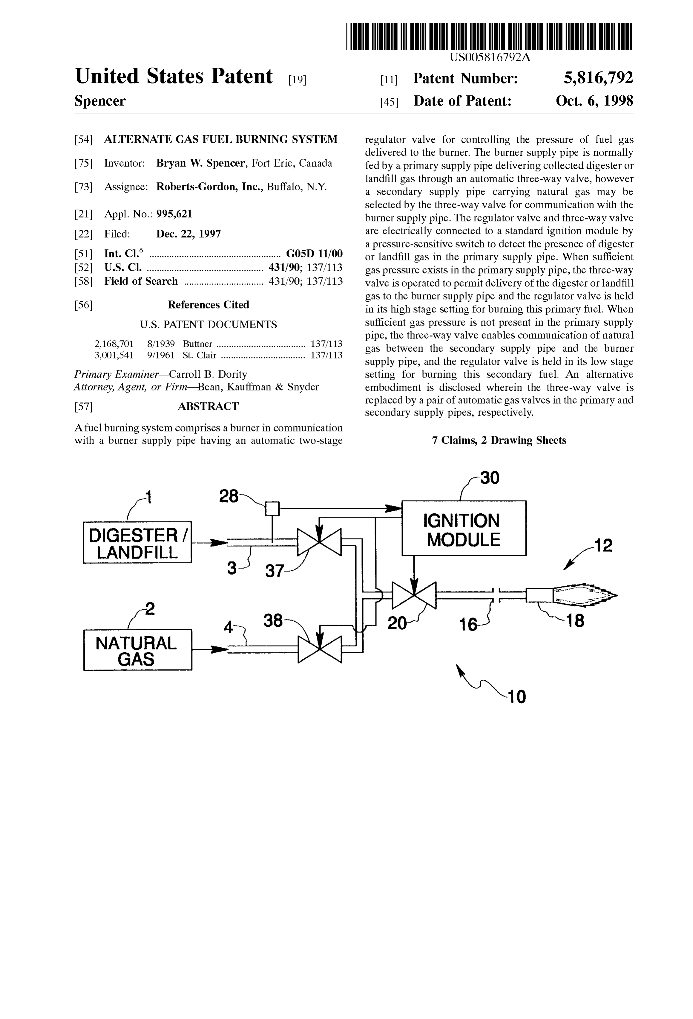
United States Patent (19) 11 Patent Number: 5,816,792 Spencer (45) Date of Patent: Oct. 6, 1998 54) ALTERNATE GAS FUEL BURNING SYSTEM regulator valve for controlling the preSSure of fuel gas delivered to the burner. The burner Supply pipe is normally 75 Inventor: Bryan W. Spencer, Fort Erie, Canada fed by a primary Supply pipe delivering collected digester or landfill gas through an automatic three-way valve, however 73 Assignee: Roberts-Gordon, Inc., Buffalo, N.Y. a Secondary Supply pipe carrying natural gas may be selected by the three-way valve for communication with the 21 Appl. No.: 995,621 burner Supply pipe. The regulator valve and three-way valve 22 Filed: Dec. 22, 1997 are electrically connected to a Standard ignition module by a preSSure-Sensitive Switch to detect the presence of digester (51) Int. Cl. ............................................... G05D 11/00 or landfill gas in the primary Supply pipe. When Sufficient 52 U.S. Cl. ............................................... 431/90; 137/113 gas pressure exists in the primary Supply pipe, the three-way 58 Field of Search ................................ 431/90; 137/113 valve is operated to permit delivery of the digester or landfill gas to the burner Supply pipe and the regulator valve is held 56) References Cited in its high Stage Setting for burning this primary fuel. When
pipe, the three-way valve enables communication of natural 2,168,701 8/1939 Buttner .................................... 137/113 gas between the Secondary Supply pipe and the burner 3,001,541 9/1961 St. Clair .................................. 137/113 Supply pipe, and the regulator valve is held in its low Stage Primary Examiner-Carroll B. Dority Setting for burning this Secondary fuel. An alternative Attorney, Agent, or Firm Bean, Kauffman & Snyder embodiment is disclosed wherein the three-way valve is 57 ABSTRACT replaced by a pair of automatic gas Valves in the primary and Secondary Supply pipes, respectively.
A fuel burning System comprises a burner in communication with a burner Supply pipe having an automatic two-stage 7 Claims, 2 Drawing Sheets
IGNITION
DIGESTER / MODULE
LANDFILL
NATURAL
GAS
Page 2
Drawing sheet — no readable text.
Page 3
Drawing sheet — no readable text.
Page 4
ALTERNATE GAS FUEL BURNING SYSTEM and distribution System. In this way, interruption in the
BACKGROUND
collection and/or distribution of digester or landfill gas will not cause an interruption in Space heating at the facility.
A. Field of the Invention
SUMMARY OF THE INVENTION
The present invention relates generally to the field of fuel burning Systems for Space and process heating, and more Therefore, it is an object of the present invention to particularly to Systems for burning methane gas produced as provide a fuel burning System for burning either a primary a byproduct of anaerobic decomposition of organic materi fuel, Such as digester gas or landfill gas, or a Secondary fuel als. having a different calorific value, Such as natural gas, using B. Description of the Prior Art the same burner and burner controls. In many Sewage treatment plants which utilize a waste It is another object of the present invention to provide a activated sludge process, the Sewage is treated in large fuel burning System which automatically Switches between anaerobic reactors commonly known as “digesters”. The a primary fuel and a Secondary fuel depending upon the gaseous respiratory products of bacteria, primarily methane 15 availability of the primary fuel. and carbon dioxide, collect within the respective top por In View of these and other objects, a fuel burning System tions of the reactors. It is known to use the collected gas, of the present invention comprises a burner in communica referred to as “digester gas”, to fire boilers which provide tion with a burner Supply pipe having an automatic two proceSS heat for the digesters and also space heat for Stage regulator valve installed there along for controlling the occupied buildings at the treatment plant. Digesters must be pressure of fuel gas delivered to the burner. The burner maintained at 98 F. to ensure the growth of the organisms Supply pipe is normally fed by a primary Supply pipe responsible for the anaerobic digestion process. Therefore, delivering collected digester or landfill gas to the burner proceSS heat is transferred to the digesters through heat Supply pipe via automatic valve means, however a Second eXchangers having heated water on a primary Side thereof ary Supply pipe carrying natural gas may be Selected by the and digester Sludge on a Secondary Side thereof. Since 25 automatic valve means for communication with the burner Sewage treatment plants are typically made up of Several Supply pipe. The regulator valve and automatic valve means buildings Separated by open tanks and channels containing are electrically connected to a Standard ignition module by Sewage at various Stages of treatment, using Steam or hot a pressure-Sensitive Switch installed to detect the presence of water for Space heating requires long runs of Supply and digester or landfill gas in the primary Supply pipe. When return piping which often must be run underground. Sufficient gas pressure exists in the primary Supply pipe, the Moreover, many of these buildings are large with high automatic valve means is operated to permit delivery of the ceilings, and are occupied intermittently. Using boilers for digester or landfill gas to the burner Supply pipe and the both process and Space heat in a Sewage treatment plant also regulator valve is held in its high stage Setting as indicated indicates the production of water at two different operating for burning this primary fuel. When Sufficient gas preSSure temperatures. The thermal transfer of process heat to the 35 is not present in the primary Supply pipe, the automatic valve digesters indicates an operating temperature of less than means favors communication of natural gas between the 120 F. to prevent “baking” of the sludge onto the transfer Secondary Supply pipe and the burner Supply pipe, and the Surface of the Secondary Side of the heat eXchangers. regulator valve is held in its low Stage Setting as indicated for However, the operating temperature indicated for Space burning this Secondary fuel.
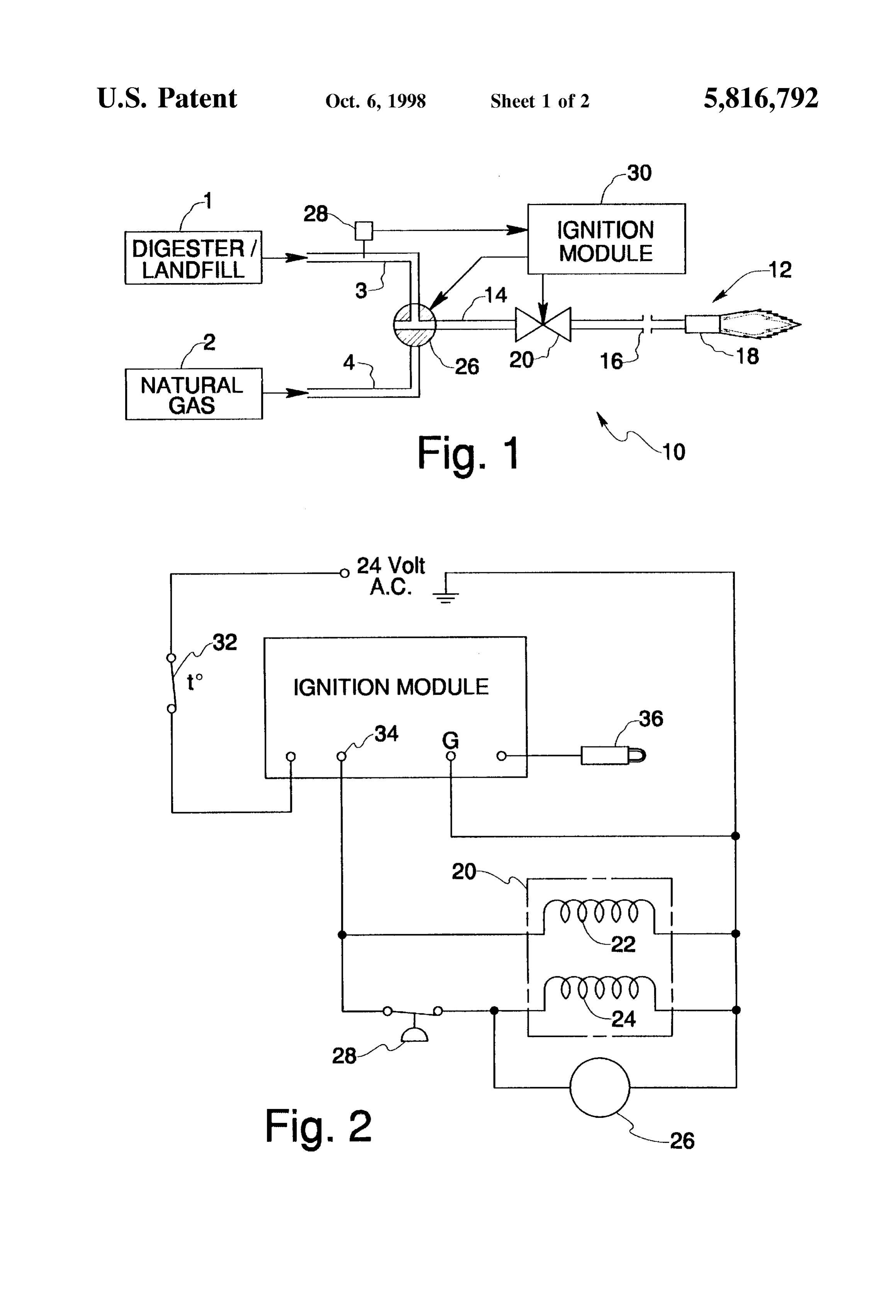
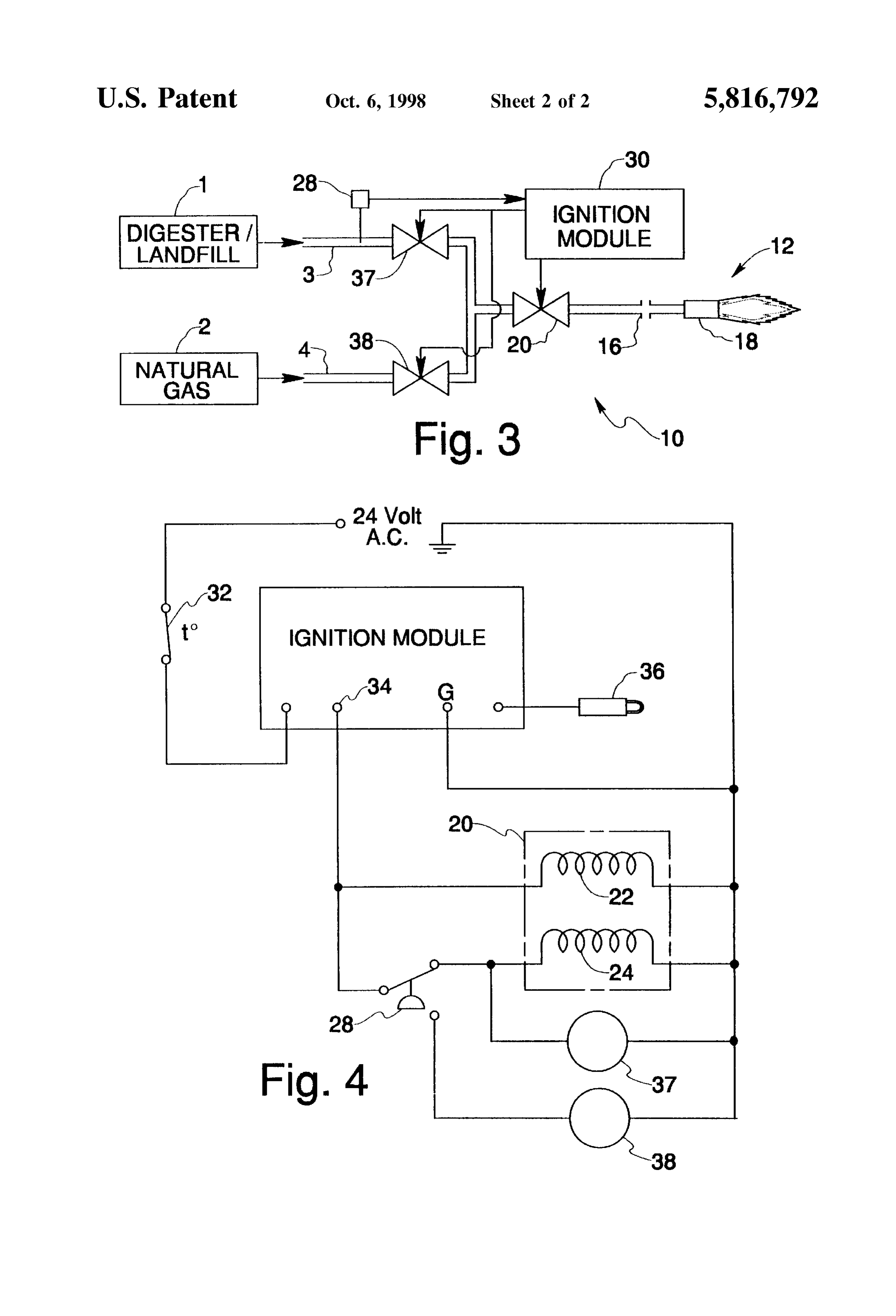
heating is about 180° F. Consequently, additional heat 40 eXchangers are necessary to accommodate for the two BRIEF DESCRIPTION OF THE DRAWINGS different operating conditions. The nature and mode of operation of the present invention Despite these problems, boilers continue to be used exten will now be more fully described in the following detailed Sively at Sewage treatment plants because the benefits of a description of the preferred embodiments taken with the free fuel Source for process heat overcome the added cost 45 accompanying drawing figures, in which: and complexities of the hydronic or Steam Systems. FIG. 1 is a Schematic diagram of a fuel burning System Nevertheless, if an alternate System of utilizing the digester formed in accordance with a preferred embodiment of the gas for Space heating fuel were available, the boilers could present invention;
be dedicated Solely to process heating. As a result, Smaller and leSS expensive boilers could be operated at the optimum 50 FIG. 2 is a Schematic wiring diagram of the fuel burning temperature for heating the digester Sludge. system of FIG. 1;
The same bacteria found in anaerobic digesters act on FIG. 3 is a Schematic diagram of a fuel burning System buried organic materials in the oxygen poor environment of formed in accordance with an alternative embodiment of the a landfill Site, producing a byproduct known as “landfill present invention; and gas”. Landfill gas is collected by a buried grid of perforated 55 FIG. 4 is a Schematic wiring diagram of the fuel burning pipes, and is almost invariably burned as waste gas because system of FIG. 3.
there is no process at a landfill site which can readily use the DETAILED DESCRIPTION OF THE steam or hot water produced by boilers. However, if an PREFERRED EMBODIMENTS alternate System utilizing digester gas for Space heating fuel were available, as mentioned above in connection with 60 Referring initially to FIG. 1 of the drawings, a fuel Sewage treatment plants, it could also be installed at a burning System formed in accordance with a preferred landfill site for heating Service buildings and the like using embodiment of the present invention is shown Schematically landfill gas. and identified generally by the reference numeral 10. Fuel Ideally, an alternate System fueled by digester or landfill burning system 10 is conventional in that it includes a burner gas should be capable of burning a backup fuel, Such as 65 12 which is fed with fuel gas by way of a burner supply pipe natural gas, which is readily available from a Secondary 14 in flow communication with a burner orifice 16 and Source independent of the digester or landfill gas collection burner cup 18. In accordance with the present invention, fuel
Page 5
burning System 10 is designed to Switch automatically threshold pressure, pressure-Sensitive Switch 28 is closed between a primary fuel Source 1, preferably collected Such that high Stage Solenoid 24 and three-way valve 26 are digester gas or landfill gas, and a Secondary fuel Source 2, energized along with low Stage Solenoid 22. Under these preferably natural gas from a utility gas line, depending conditions, primary Supply pipe 3 is Selected for communi upon whether Sufficient Supply of the primary fuel is avail cation with burner Supply pipe 14 by energized three-way able. valve 26, thereby allowing fuel from primary fuel source 1 Referring also now to FIG. 2, a two-stage regulator valve to flow through regulator valve 20 electrically held at its 20 is installed along burner Supply pipe 14 upstream of high Stage Setting. Accordingly, digester or landfill gas burner 12. Regulator valve 20 internally includes a low stage undergoes combustion at burner 12.
Solenoid 22 and a high Stage Solenoid 24 for automatically If the preSSure of digester or landfill gas within primary controlling the pressure of fuel gas delivered to burner 12. Supply pipe 3 is not above the threshold pressure required to When regulator valve 20 is in its high Stage Setting, namely maintain pressure-Sensitive Switch 28 in its closed State, the when both low Stage Solenoid 22 and high Stage Solenoid 24 preSSure-Sensitive Switch opens to electrically disconnect are energized, fuel gas is Supplied to burner 12 at a first high Stage Solenoid 24 and three-way valve 26. AS men preSSure, when regulator valve 20 is in its low Stage Setting, 15 tioned above, when the Solenoid of three-way valve 26 is not namely when only low Stage Solenoid 22 is energized, fuel energized, Secondary Supply pipe 4 communicates with gas is Supplied to burner 12 at a Second pressure less than the burner Supply pipe 14 to the exclusion of primary Supply first pressure associated with the high Stage Setting. A pipe 3. Consequently, natural gas from Secondary Source 2 Suitable automatic regulator valve for use in practicing the will flow through regulator valve 20 set at its low stage to present invention is manufactured by White-Rodgers under deliver natural gas for combustion at burner 12. If gas Part No. 36E96. The high stage setting of regulator valve 20 preSSure within primary Supply pipe 3 increases Sufficiently is used to regulate the pressure of digester or landfill gas, to close preSSure-Sensitive Switch 28, the System will auto which has a lower calorific value than natural gas, from 11 matically switch over to the primary fuel as described above. inches water column to 10 inches water column; the low The System will of course shut down upon opening of Stage Setting of regulator valve 20 is used to regulate the 25 thermostat Switch 32 incident to rising temperature. preSSure of natural gas from 7 inches water column to 3 An alternate embodiment of the present invention is inches water column. shown in FIGS. 3 and 4. The alternate embodiment is Burner Supply pipe 14 is fed either by primary Supply pipe identical to the preferred embodiment, except that a pair of 3 delivering digester or landfill gas from primary fuel Source automatic gas valves 37 and 38 are used in place of 1, or by Secondary Supply pipe 4 delivering natural gas from three-way valve 26. Gas valve 37 is installed along primary Secondary fuel Source 2. An automatic three-way valve 26 is supply pipe 3 to control the flow of fuel from primary fuel provided at the junction of primary Supply pipe 3, Secondary Source 1, while gas valve 38 is installed along Secondary Supply pipe 4, and burner Supply pipe 14 for enabling a supply pipe 4 to control the flow of fuel from secondary fuel Selected one of Supply pipes 3,4 to communicate with burner 35 Source 2. AS may be seen from FIG. 4, pressure-Sensitive Supply pipe 14 while excluding the other of Supply pipes 3,4 Switch 28 electrically connects high Stage Solenoid 24 and from communication with the burner Supply pipe. A three gas valve 37, and electrically disconnects gas valve 38, way valve manufactured by ASCO under Part No. when Sufficient gas pressure exists within primary Supply 8300D68RU is of a type which will perform this function. pipe 3. This enables flow communication between primary In the presently described embodiments, automatic three Supply pipe 3 and burner Supply pipe 14, and holds regulator way valve 26 is installed such that when its Solenoid is not 40 Valve 20 in its high Stage Setting, as required for burning energized, it Selects Secondary Supply pipe 4 for exclusive landfill or digester gas. When gas pressure within primary communication with burner Supply pipe 14. Supply pipe 3 is not above the threshold pressure necessary A pressure-Sensitive Switch 28 is installed along primary for burning digester or landfill gas from primary fuel Source Supply pipe 3 for detecting whether or not gas pressure 45 1, pressure-Sensitive Switch 28 electrically disconnects high within the primary Supply pipe is above a predetermined Stage Solenoid 24 and gas valve 37, and electrically connects threshold pressure, preferably 10 inches water column. A gas Valve 38, thereby opening flow communication between Honeywell gas Switch Part No. C637B, or similar type gas Secondary Supply pipe 4 and burner Supply pipe 14 and Switch, is Suitable. placing regulator valve 20 in its low Stage Setting for burning A Single flame-Sensing ignition module 30, connected in 50 natural gas from Secondary fuel Source 2. What is claimed is:
a known manner across an 24 Volt A.C. power Source by 1. A fuel burning System comprising: way of a thermostat switch 32, provides control functions for the System. AS may be seen in FIG. 2, low Stage Solenoid 22 a burner, of regulator valve 20 is electrically connected between the a burner Supply pipe delivering fuel to Said burner, valve control terminal 34 of ignition module 30 and ground, 55 a primary Supply pipe connected to Said burner Supply and remains energized regardless of whether pressure pipe for delivering fuel from a primary fuel Source; Sensitive Switch 28 is open or closed. High Stage Solenoid 24 a Secondary Supply pipe connected to Said burner Supply and three-way valve 26 are electrically connected between pipe for delivering fuel from a Secondary fuel Source; Valve control terminal 34 and ground by way of pressure preSSure Sensing means installed along Said primary Sup sensitive Switch 28. A flame sensor 36 is also shown as being 60 ply pipe for detecting a primary fuel pressure in Said connected to ignition module 30. primary Supply pipe;
System operation of the preferred embodiment is now automatic valve means for Selecting between said primary described in conjunction with FIGS. 1 and 2. When ther and Secondary Supply pipes for exclusive communica mostat Switch 32 closes due to falling temperature, the tion with Said burner Supply pipe, Said automatic valve ignition module 30 is activated and the low stage Solenoid 22 65 means being operably connected to Said preSSure Sens of regulator valve 20 is energized. If the pressure of digester ing means for choosing Said primary Supply pipe for or landfill gas in primary Supply pipe 3 is above the exclusive communication with Said burner Supply pipe
Page 6
S 6 when Said primary fuel pressure is above a threshold 3. The fuel burning System according to claim 1, wherein preSSure, and for choosing Said Secondary Supply pipe Said fuel from Said primary fuel Source is landfill gas. for exclusive communication with Said burner Supply pipe when Said primary fuel preSSure is not above Said Said4. The fuel fuel burning System according to claim 1, wherein from Said Secondary fuel Source is natural gas.
threshold pressure, and an automatic regulator Valve installed along Said burner 5. The fuel burning System according to claim 1, wherein Supply pipe upstream of Said burner for regulating fuel Said automatic valve means comprises a three-way valve flow within Said burner Supply pipe, Said regulator connecting Said primary and Secondary Supply pipes to Said Valve having a high Stage Setting for delivering fuel to burner Supply pipe for Selective communication there with. Said burner at a first pressure and a low Stage Setting for 6. The fuel burning System according to claim 1, wherein delivering fuel to Said burner at a Second preSSure, Said Said automatic valve means comprises a pair of automatic regulator valve being operably connected to Said pres gas valves installed one along each of Said primary and Sure Sensing means for choosing Said high Stage Setting when Said primary fuel pressure is above Said threshold Secondary operably
Supply pipes, each of Said pair of gas valves being connected to Said pressure Sensing means.
preSSure, and for choosing Said low Stage Setting when 15
Said primary fuel pressure is not above Said threshold 7. The fuel burning System according to claim 1, wherein preSSure. Said pressure Sensing means is a pressure Sensitive Switch. 2. The fuel burning System according to claim 1, wherein
Said fuel from Said primary fuel Source is digester gas. k k k k k
Provenance
- Collection
- Cited prior art
- Original PDF
- patentimages.storage.googleapis.com →
- Filed
- 1997-12-22
- Pages
- 6
- Method
- pdftotext (the PDF's own text layer) + pdftoppm 300dpi page scans
- Source
- Google Patents bibliographic record
- Granted
- 1998-10-06
- Inventors
- Bryan W. Spencer; Roberts Gordon Inc
- Transcribed from
- patentimages.storage.googleapis.com →