patent · US4210632
Process and apparatus for calcining limestone
1 July 1980
Page 1 — bibliographic record
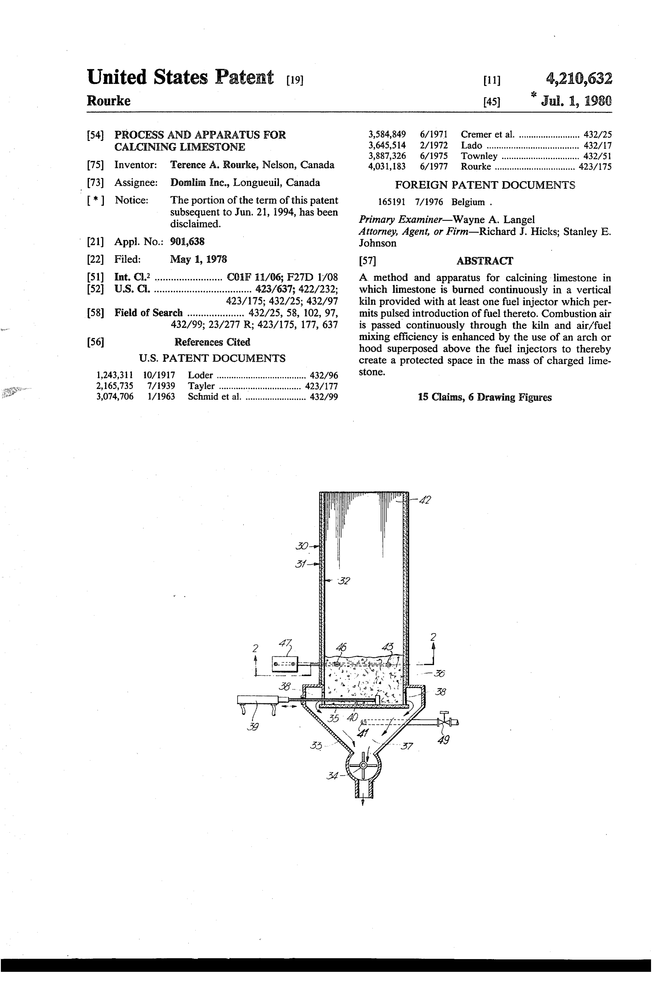
United States Patent (19) 11 4,210,632 Rourke (45) Jul. 1, 1980 (54) PROCESS AND APPARATUS FOR 3,584,849 6/1971 Cremer et al. ... ... 432/25 CALCNNG LIMESTONE 3,645,514 2/1972 Lado ................ ... 432/17 3,887,326 6/1975 Townley .. ... 432A51 75) Inventor: Terence A. Rourke, Nelson, Canada 4,031, 183 6/1977 Rourke ................................. 423/175 (73) Assignee: Domlin Inc., Longueuil, Canada FOREIGN PATENT DOCUMENTS *) Notice: The portion of the term of this patent 165191 7/1976 Belgium.
subsequent to Jun. 21, 1994, has been Primary Examiner-Wayne A. Langel disclaimed.
Attorney, Agent, or Firm-Richard J. Hicks; Stanley E.
(21) Appl. No.: 901,638 Johnson 22 Filed: May 1, 1978 57 ABSTRACT 51) Int. C.2 ....... ... C01 F 11/06; F27D 1/08 A method and apparatus for calcining limestone in 52 U.S.C. .................................... 423/637; 422/232; which limestone is burned continuously in a vertical 423/175; 432/25; 432/97 kiln provided with at least one fuel injector which per 58) Field of Search ..................... 432/25, 58, 102, 97, mits pulsed introduction of fuel thereto. Combustion air 432/99; 23/277 R; 423/175, 177,637 is passed continuously through the kiln and air/fuel 56 References Cited mixing efficiency is enhanced by the use of an arch or hood superposed above the fuel injectors to thereby
1,243,311 10/1917 Loder ..................................... 432/96 Stone.
a'" 2,165,735 7/1939 Tayler ............ . . . . . . . . . . . . . . . . . 423/177 2 3,074,706 1/1963 Schmid et al. ......................... 432/99 15 Claims, 6 Drawing Figures
Page 2
Drawing sheet — no readable text.
Page 3
Drawing sheet — no readable text.
Page 4
Thus, it is an object of the present invention to
PROCESS AND APPARATUS FOR CALCENING provide an improved vertical kiln for the continuous LIMESTONE production of calcined lime from limestone.
By one aspect of this invention there is provided a
This application relates to a vertical shaft kiln or 5 process for the continuous production of calcined lime furance for calcining limestone and the like. in a vertical kiln in which fuel is injected, through at This application is related to my earlier filed U.S. least one injector spaced from the lower end of the kiln, application Ser. No. 559,193 filed Mar. 17, 1975 and at a pulsed rate between 100 and 1,000 injections per now abandoned, C.I.P. application Ser. No. 658,576 injector per minute, with each of said injections occur ring within a time period of up to one third of the pulse filed Feb. 17, 1976 now U.S. Pat. No. 4,031,183 issued 10 period,
June 21, 1977 and divisional application Ser. No. through the and air is passed continuously upwardly 706,112 filed Jan. 17, 1977, the disclosures of which are therethroughkiln and countercurrent to the passage of lime in an amount sufficient to support incorporated herein by reference. combustion, and wherein a protected space is provided in the aforesaid applications there is described a pro 15 in said kiln adjacent said injectors. cess and apparatus for the continuous production of By another aspect of this invention there is provided calcined line from limestone in a vertical kiln in which fuel is supplied intermittently through a plurality of an apparatus for the production of the clacined lime comprising:
injectors circumferentially spaced around the kiln in a a refractory lined vertical shaft provided with mate single horizontal plane spaced from the lower end of the rial feed means and gas exhaust means at the upper end kiln and combustion air is supplied continuously to the thereof;
kiln, countercurrent to the downward flow of lime means to withdraw calcined lime from the lower end stone, from a level below the fuel injectors. The fuel is of said apparatus;
injected at a pressure in the range between 2,000 and means for introducing air in an amount sufficient to 15,000 psi through each of the injectors in a predeter- 25 support combustion in said apparatus to the lower end mined sequence at a pulse rate of between 100 and 500 of said apparatus;
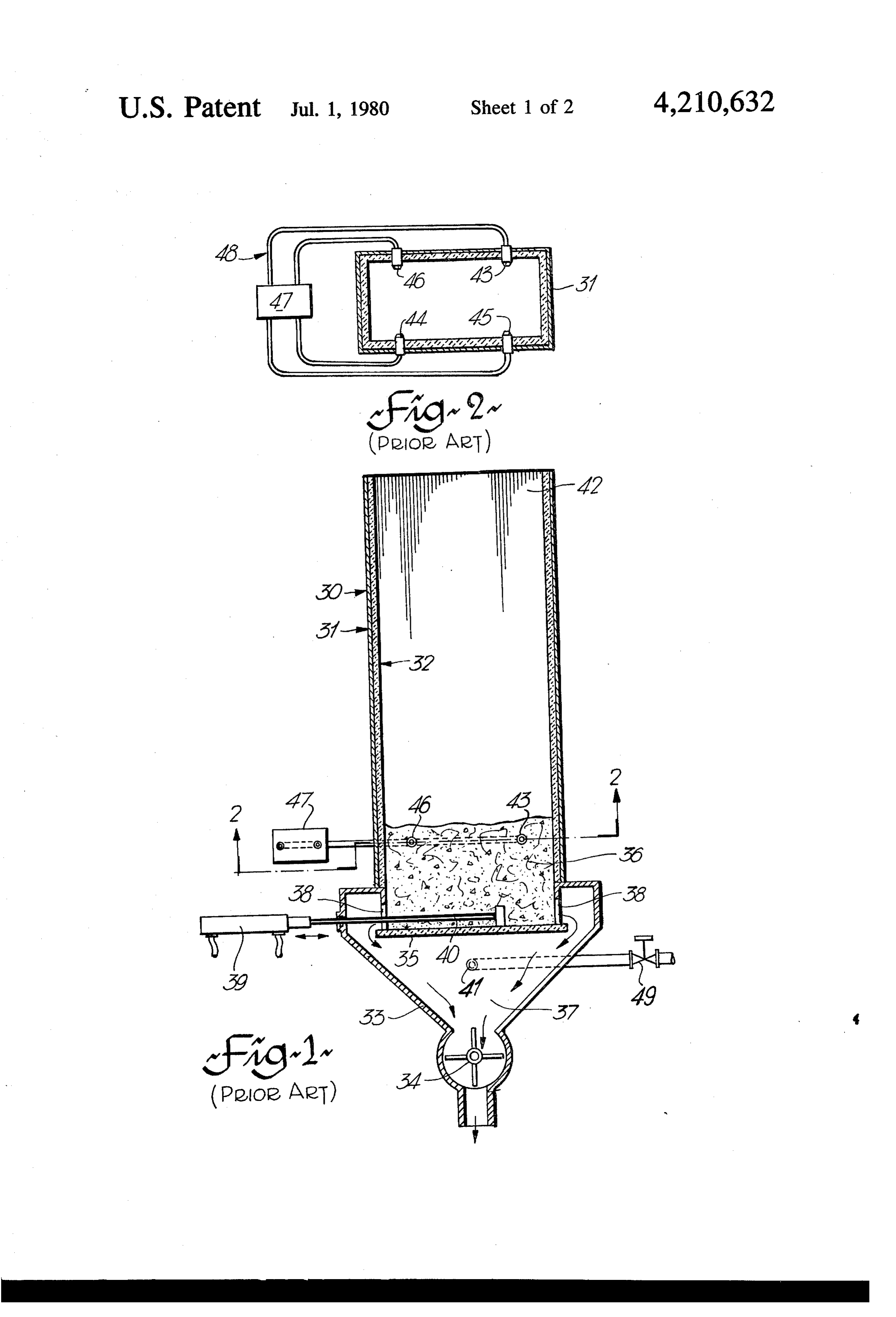
injections per injector per minute, each of the injections at least one injector means spaced from said lower occurring in a time period between 0.02 and 0.2 sec end of said apparatus for introducing fuel into said shaft; onds. The fuel injection system is preferably based on means for supplying fuel to said injector means at a the pump and fuel injector system of a conventional 30 rate between 100 and 1000 injections per minute; and diesel engine and in a kiln designed to produce 5 tons/- deflector means vertically disposed above said injec day of calcined lime, i.e. having a shaft height of about tor means in said shaft, thereby creating a protected 8 feet and a cross sectional area of 2 square feet, substan spaced adjacent said injectors. tially complete fuel combustion can be achieved at a The invention will be described hereinafter with ref fuel efficiency (theoretical fuel requirement divided by 35 erence to the drawings in which: actual fuel used) which approaches 100%, under the FIG. is a cross sectional view of a kiln according to aforesaid conditions. It was believed that the pulsing my earlier invention;
effect, at relatively high pressure, was essential to FIG. 2 is a plan view along line 2-2 of the kiln achieve the high fuel efficiencies which were in fact shown in FIG. ;
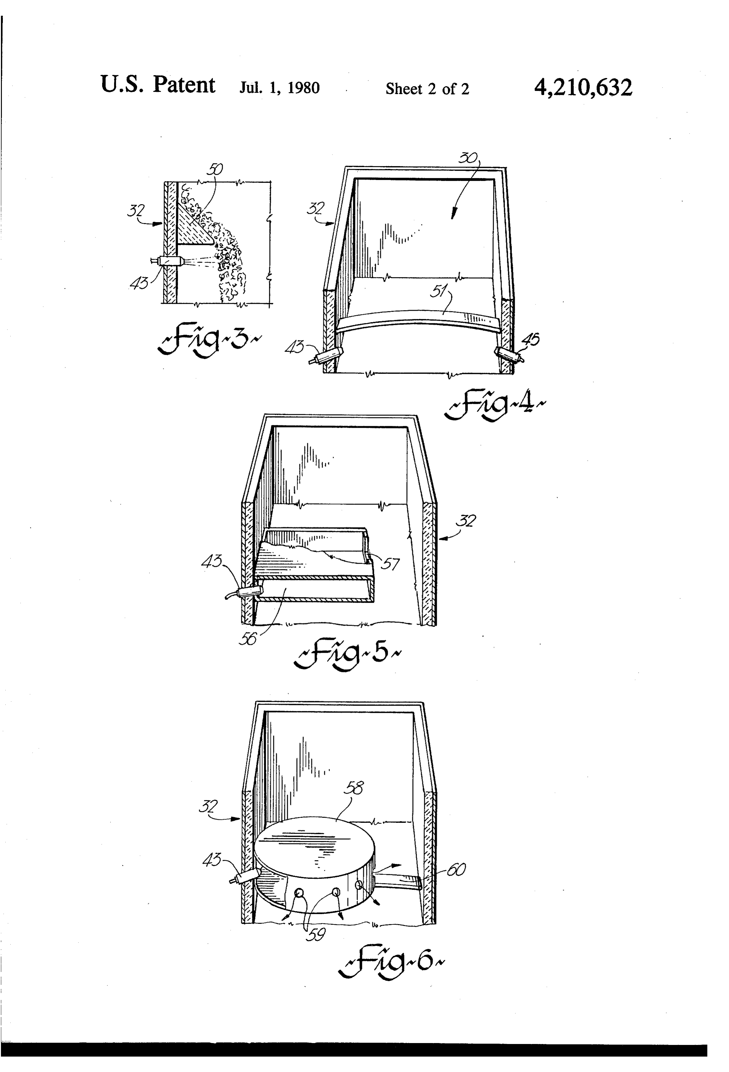
FIG. 3 is an enlarged cross sectional view of the fuel achieved. On this basis, therefore when scaling up the 40 injector kiln to a shaft height of the order of 16 feet and a cross portion of the kiln of FIG. incorporating an section of the order of 3 feet by 6 feet, it would appear embodiment of the present invention; that the pressures required to achieve the so-called FIG. 4 is an enlarged cross sectional view, similar to "lamellar flow' i.e. alternate layers of air, fuel and air FIG. 3, showing an alternative form of the present fuel mixtures in the combustion zone, would be the 45 invention;
FIG. 5 is a sketch similar to FIGS. 3 and 4 of a further same or greater than the heretofore employed 2,000 to embodiment of the present invention; and 15,000 psi range. Surprisingly, however, it has now FIG. 6 is a sketch of yet another embodiment of the been found that substantially complete combustion and present invention.
high efficiencies can be achieved at pressures as low as 50 In FIGS. 1 and 2 there is illustrated a preferred for in 100 psi, but preferably at about 1,000 psi, when a some of kiln according to my prior invention, as described in what modified furnace, as described in more detail here detail in my U.S. Pat. No. 4,031,183 issued fune 21, inafter, is employed. It is now believed that the high fuel 1977. Briefly this kiln comprises a vertical shaft, shown efficiency of the operation is a function of a gasifying and partial mixing space adjacent the fuel injectors to ss generally at 30, having a rectangular cross section, as shown in FIG. 2. The shaft 30 is provided with a steel bring the fuel as rapidly as possible up to the tempera shell 31 lined with basic refractory brick 32, such as ture of the surrounding area and the resulting rapid “MAGNECON” (R). The shaft is supported in the verti expansion of the fuel further aids the "lamellar flow” cal position by any convenient and conventional means combustion process. (not shown) and is connected to a sheet steel tapered Also, as the pulse rate is adjusted to the size of stone 60 base member 33, which is provided with an airlock 34 being calcined, the production capacity of the kiln, the through which burned lime may be discharged. A mild quality of stone being calcined, and the quality and steel draw feeder plate 35 of slightly larger dimensions reactivity of the lime being produced, it has been found to those of the shaft is supported in a horizontal plane that a pulse rate as high as a 1,000 injections per minute within the tapered base 33 and somewhat below the can sometimes be desirable. Although pressure may be 65 bottom of shaft 30, so as to provide a baffle for burned one, in situ, way of achieving a mixing space, at least in material 36 falling into the base cooling hopper 37, relatively small diameter kilns, it is not believed to be through peripheral space or gap 38. A hydruatic draw critical perse. cylinder 39 powers a ran 40 which reciprocates across
Page 5
the surface of plate 35 to draw burned material over adjacent thereto. The size of the space is, of course, a alternate peripheral edges of plate 35 and down into function of the angle of repose of the limestone charge hopper 37 through gap 38. Limestone generally in the and of the dimensions of the hood. As will be appreci size range of 5/16'-3", "-1", 1'-2', 2'-5" with a ated by those skilled in the art, such a protected space size ratio 1:2 is fed to the top 42 of the shaft 30, via a can be provided in any of a considerable number of conventional kiln charging mechanism (not shown), to alternative ways, some of which are shown in FIGS. 4, form a permeable column supported by feeder plate 35. 5 and 6.
It will be appreciated that although limestone up to In FIG. 4 there is shown a kiln 30 having opposed about 2' is normally employed, material up to about 5' walls 32, an injector nozzle 43 and immediately adjacent may also be treated, depending on kiln size and specific 10 thereto and spanning the kiln between walls 32 an arch operating techniques. Combustion air is introduced or plate 51 which serves substantially the same function through a valve 49 and inlet 41 in hopper 37 from an as hood 50 in FIG.3 to deflect the limestone away from externai air compressor (not shown), so as to give a the injector nozzle and create a void space. The arch or positive pressure in the cooling hopper 37 of approxi plate 51 is conveniently fabricated from refractory brick mately 4:" H2O. The combustion air passes upwardly 15 such as MAGNECON (R), or it may be a hollow steel through openings 38 and is preheated by the descending plate structure which may, optionally, be water cooled. burned lime which is in turn cooled so that it is dis The arch 51 is generally 3' to 12" wide and extends charged from airlock 34 at approximately 100-200 F. across the kiln and thus covers, taking the example of Air is introduced in sufficient quantity to support com the kiln depicted in FIG. 2, injectors 43 and 45. Of bustion and for maximum efficiency the oxygen content 20 course, a second bridge or arch is provided to superpose of the exhaust gases should be substantially zero. In any injectors 44 and 46.
event it is preferred that the oxygen content should be In FIG. 5 there is shown one form of a gas box 56 less than about 5%, so that the amount of air required which may be fabricated around an individual injector may be simply monitored by analysis of the exhaust nozzle 43. Box 56 is generally fabricated in refractory gases. 25 brick or steel and, again, functions to provide an air it will be appreciated that many modifications to this protected space 57, substantially out of direct contact basic structure are possible and that certain elements with the falling charge of limestone. It will be appreci therein are not essential. For example the draw feeder ated that with the use of a box. 56, a plurality of injector plate 35 is not essential and many other ways of with nozzles may not be necessary as the fuel distribution drawing the calcined product may be employed. Also 30 across the kiln is considerably improved. A single injec air flow through the kiln may be achieved by means of tor nozzle is generally all that is required. exhaust fans at the top of the kiln to draw air through In order to still further improve fuel distribution, a the kiln.
further
Fuel oil is injected under a pressure of the order of A gas box modification of the gas box is shown in FIG. 6. 58 is provided with a plurality of peripheral 2,000 to 15,000 psi and preferably 6,000 to 8,000 psi into 35 slots or ports 59 through which the fuel is dispersed the charged stone column through conventional fuel substantially uniformly across the combustion zone. injectors 43, 44, 45 and 46, in a pulsed sequence, is Generally only a single injector nozzle 43 is required in moved upwardly and then admixed with the continu the gas box. As box 58 is relatively large and must with ously upwardly flowing preheated air. It then ignites stand substantial abrasive and other forces it is normally and burns with a long flame. For simplicity and conve supported on an arch 60 which spans the kiln in the nience, it has been found that a fuel injection pump 47 manner of arch 51 of FIG. 4. As pointed out herein and system 43 from a conventional diesel engine is ideal. above, a principal object of the present invention is to In such a diesel engine pump it has been found that achieve uniform fuel distribution to thereby achieve operating at a speed of about 100 to 1,000 rpm the afore maximum efficiency of combustion. It has been found said "lamellar' flow of fuel and air through the shaft 45 that the shortest possible injection period is the most can be achieved. In the kiln shown in FIGS. 1 and 2, efficient, and that the kiln capacity can be controlled by which is designed as a 5 ton/day kiln with a shaft cross the volume of air and its related fuel requirement. In section of i'X2' and a shaft height of 8, four fuel injec general, as the velocity increases the pulse rate of the tors 43, 44, 45 and 46 are shown and have been found fuel injection is also increased.
satisfactory to achieve lamellar flow. 50 I claim:
Upon scaling up the aforesaid kiln to a shaft height of 1. A process for the continuous production of cal about 16 feet, with a hearth 3'X6' and with a through cined lime in a vertical kiln, in which fuel is injected, put of 60 tons of lime per day the aim is still to achieve through at least one injector spaced from the lower end complete combustion of the fuel at the top of the calcin of the kiln, at a pulsed rate between 100 and 1,000 injec ing Zone, as measured by gas analysis at the gas exhaust. 55 tions per injector per minute, each of said injections Because the weight of charged limestone is greater and occurring in a time period of up to one third of the pulse the gas must penetrate a greater distance from the injec period, and air is passed continuously upwardly, coun tion nozzle, it would appear to follow that the fuel tercurrent to the passage of lime, through the kiln from pressure required is also greater. The increase in pres a position below said injector and in an amount suffi sure can be avoided, however, and indeed the fuel pres cient to support combustion, and wherein a protected sure lowered to as low as 100 psi if the kiln is modified void space is provided in said kiln adjacent and verti as shown in FIGS. 3-6. cally above said injectors so as to form a mixing space in FIG. 3, there is shown a section of the kiln wall 32, for said fuel and air.
immediately adjacent any one of nozzles 43-46, with a 2. A process as claimed in claim wherein said fuel is small brick or metal hood 50, preferably but not essen 65 a liquid fuel oil.
tially triangular in shape. Hood 50 serves to deflect the falling charge 36 of limestone from the immediate vicin oil3.isAinjected process as claimed in claim 2 wherein said fuel at a pressure in the range between about ity of the nozzle and, in effect, creates a protected space 100 to 2,000 psi.
Page 6
4. A process as claimed in claim 1 wherein said fuel is supply said fuel at a pressure in the range between 100 injected at a pressure in the range between about 100 and 15,000 psi.
and 15,000 psi. 8. An apparatus as claimed in claim 7 wherein said 5. A process as claimed in claim 1 wherein said fuel is means for supplying fuel comprises pump means to injected at a pressure in the range between about 2,000 about 100liquid supply a and fuel at a pressure in the range between
6. An apparatus for the production of calcined lime means for supplying claimed 9. An apparatus as in claim 7 wherein said fuel comprises pump means to comprising: a refractory lined vertical shaft provided supply fuel at a pressure in the range between 2,000 and with material feed means and gas exhaust means at the 10 15,000 psi.
upper end thereof; 10. An apparatus as claimed in claim 6 wherein said means to withdraw calcined lime from the lower end deflector means comprises arch means extending across of said apparatus; said shaft and disposed vertically above said injector at least one injector means spaced from said lower eaS.
end of said apparatus for introducing fuel into said 15 11. An apparatus as claimed in claim 10 wherein said shaft; arch means is disposed vertically above a pair of mutu means for supplying fuel to said injector means at a ally horizontally opposed injector means. rate between 100 and 1,000 injections per minute; 12. An apparatus as claimed in claim 6 wherein said means for passing air, in an amount sufficient to sup 20 deflector rounding comprises box means at least partially sur said injector.
port combustion in said apparatus, through said 13. An apparatus as claimed in claim 12 wherein said apparatus from a position below said injector box means is supported on arch means in said shaft. means; and 4. An apparatus as claimed in claim 6 including a deflector means disposed vertically above and spaced plurality of injector means spaced around said shaft in a from said injector means in said shaft, thereby cre 25 horizontal plane.
ating a protected void space adjacent and above 15. An apparatus as claimed in claim 6 wherein said said injector means in which said air and fuel mix. deflector means comprises hood means secured to said 7. An apparatus as claimed in claim 6 wherein said shaft vertically aboves: each it said injector
means.
means for supplying fuel comprises pump means to
Provenance
- Collection
- Cited prior art
- Original PDF
- patentimages.storage.googleapis.com →
- Filed
- 1978-05-01
- Pages
- 6
- Method
- pdftotext (the PDF's own text layer) + pdftoppm 300dpi page scans
- Source
- Google Patents bibliographic record
- Granted
- 1980-07-01
- Inventors
- Terence A. Rourke; Domlim Inc
- Transcribed from
- patentimages.storage.googleapis.com →