patent · US5577493A
Auxiliary lens to modify the output flux distribution of a TIR lens
26 November 1996
Page 1 — bibliographic record
United States Patent (19) 11) Patent Number: 5,577,493 Parkyn, Jr. et al. 45 Date of Patent: Nov. 26, 1996 (54) AUXILIARY LENS TO MODIFY THE 4,116,223 9/1978 Vasilantone. OUTPUT FLUX DESTRIBUTION OF ATR 4,124,017 11/1978 Paull. LENS 4,136,670 1/1979 Davis.
(75) Inventors: William A. Parkyn, Jr., Costa Mesa; 4,194,949 3/1980 Stark. David G. Pelka, Los Angeles, both of 4,198.953 4f1980 Power ................................. 1261699 X Calif. 4,282,858 8/1981 Bowers, Jr. ......................... 1261699 X 4,299,201 1/1981 Tsubota ............................... 126/700 X 4,337,759 7/1982 Popovich et al. ................... 126/698 X 73) Assignee: TIR Technologies, Inc., Carson City, 4,755,921 7/1988 Nelson. Nev. 4,805,984 2/1989 Cobb, Jr. ................................. 385/133 5,059,013 10/1991 Jain ....................................... 359/503 (21) Appl. No.: 294,223 5,150,966 9/1992 Nelson. 5,381.309 1/1995 Borchardt .................................. 362/31 22 Filed: Aug. 22, 1994 FOREIGN PATENT DOCUMENTS Related U.S. Application Data 1325086 8/1973 United Kingdom.
63 Continuation-in-part of Ser. No. 869,003, Apr. 16, 1992, Pat. 54.6791 5/1979 United Kingdom . No. 5,404,869. 1546792 5/1979 United Kingdom.
51 Int. Cl. .......................... F24, 2/08 1557472 12/1979 United Kingdom. 52 U.S. Cl. ................ ... 126/699; 126/698; 126/700 1561129 2f1980 United Kingdom. 58 Field of Search ..... a - -- -- - - - - - - - - - -- - - - -- - 126/698, 699, 2239939 1/1993 United Kingdom.
56) References Cited Primary Examiner-Larry Jones Attorney, Agent, or Firm-William W. Haefliger
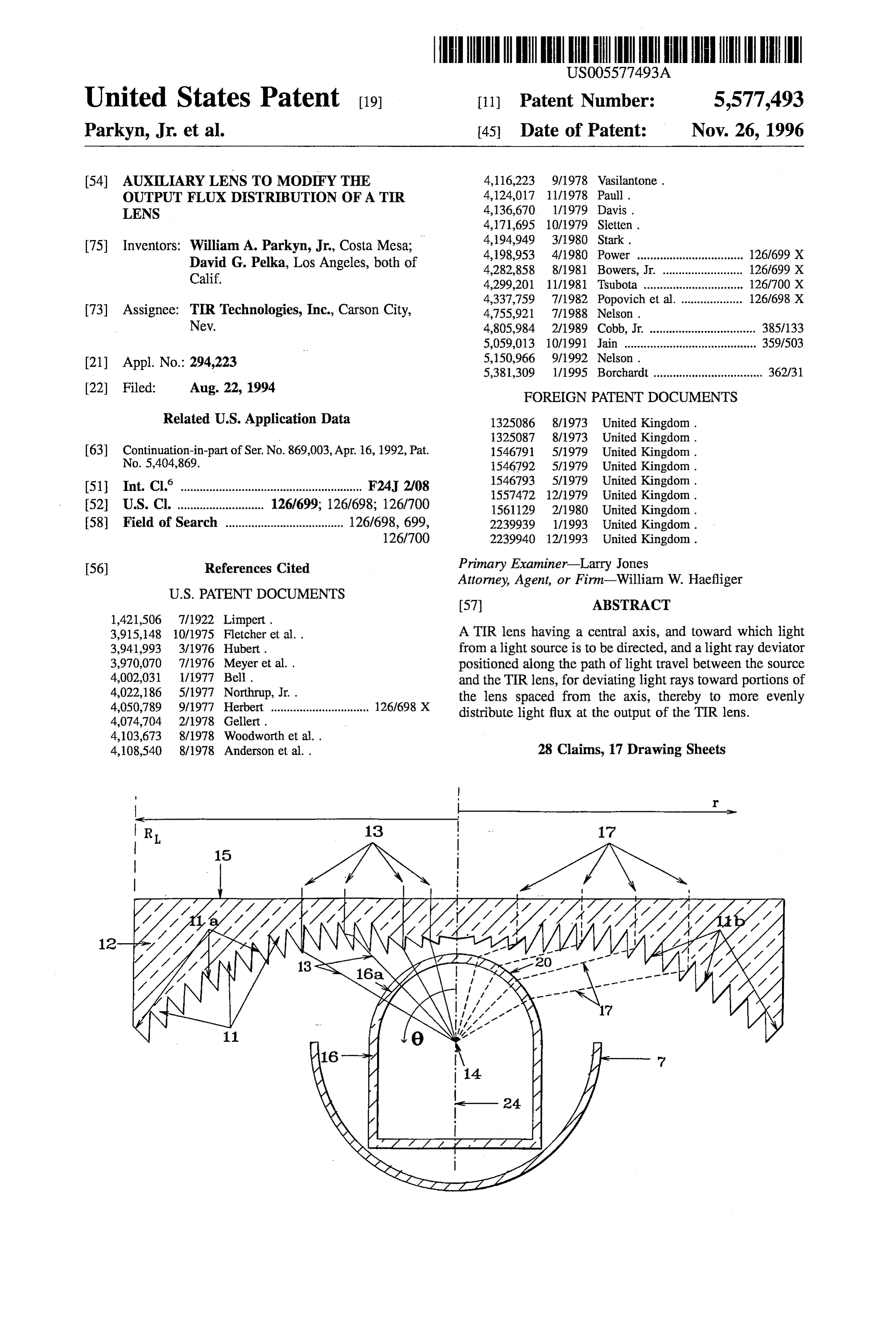
3,915,148 10/1975 Fletcher et al. . A TIR lens having a central axis, and toward which light 3,941,993 3/1976 Hubert. from a light source is to be directed, and a light ray deviator 3,970,070 7/1976 Meyer et al.. positioned along the path of light travel between the source 4.002031 1977 Bell. and the TIR lens, for deviating light rays toward portions of 4,022, 186 5/1977 Northrup, Jr. . the lens spaced from the axis, thereby to more evenly 4,050,789 9/1977 Herbert ............................... 1261698 X distribute light flux at the output of the TIR lens.
4,108,540 8/1978 Anderson et al. . 28 Claims, 17 Drawing Sheets
Page 2
Drawing sheet — no readable text.
Page 3
Drawing sheet — no readable text.
Page 4
Drawing sheet — no readable text.
Page 5
Drawing sheet — no readable text.
Page 6
Drawing sheet — no readable text.
Page 7
Drawing sheet — no readable text.
Page 8
Drawing sheet — no readable text.
Page 9
Drawing sheet — no readable text.
Page 10
Drawing sheet — no readable text.
Page 11
Drawing sheet — no readable text.
Page 12
Drawing sheet — no readable text.
Page 13
Drawing sheet — no readable text.
Page 14
Drawing sheet — no readable text.
Page 15
Drawing sheet — no readable text.
Page 16
Drawing sheet — no readable text.
Page 17
Drawing sheet — no readable text.
Page 18
Drawing sheet — no readable text.
Page 19
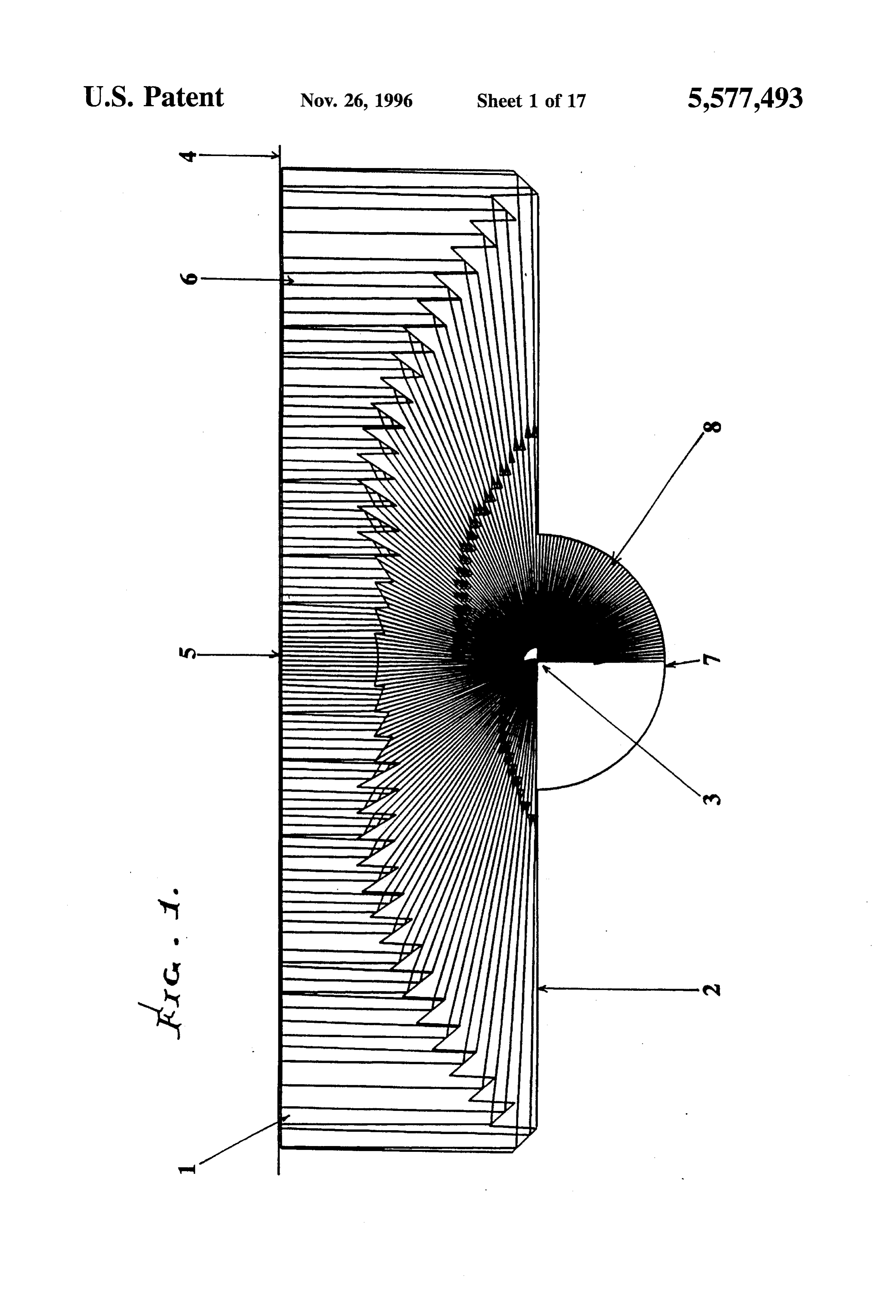
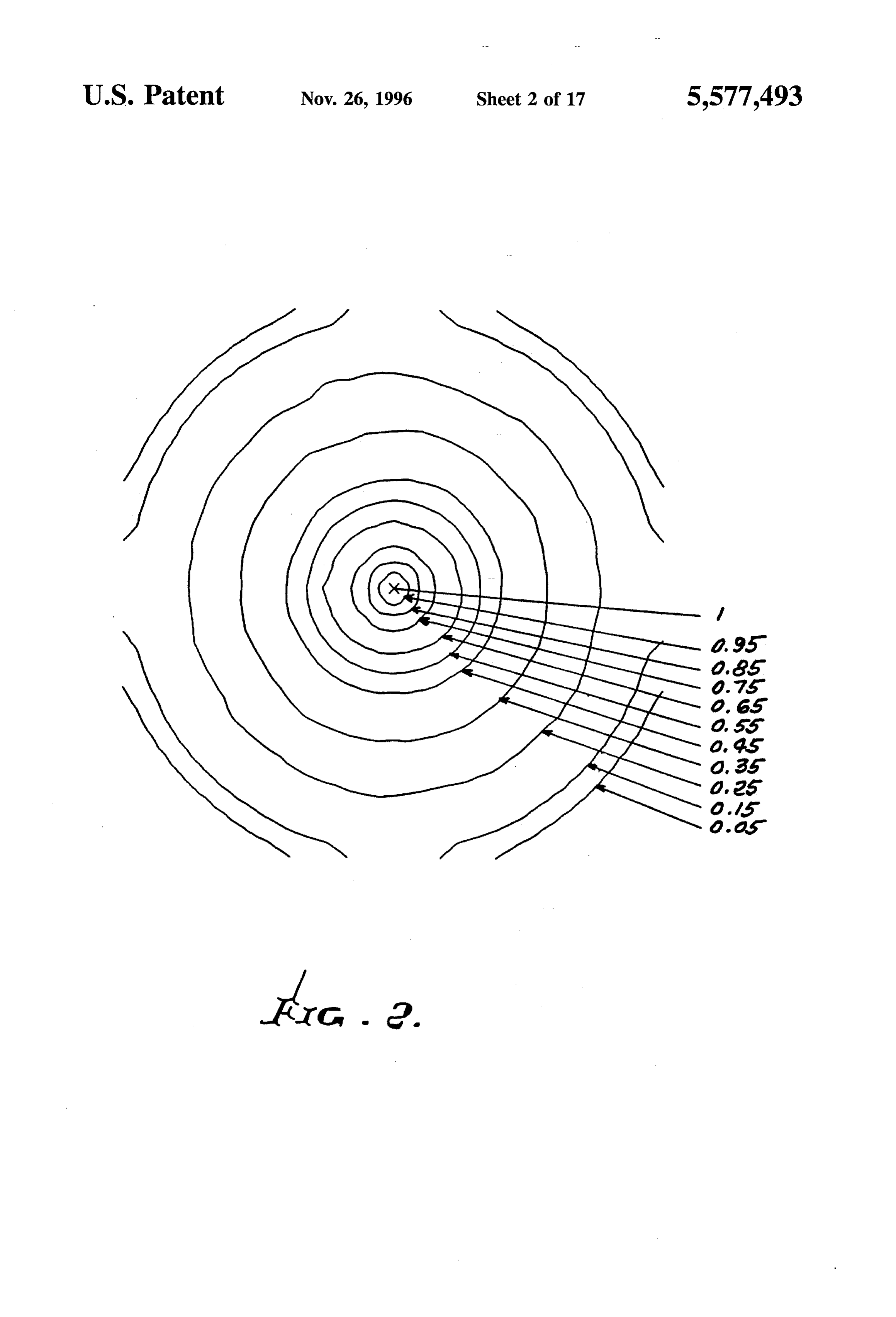
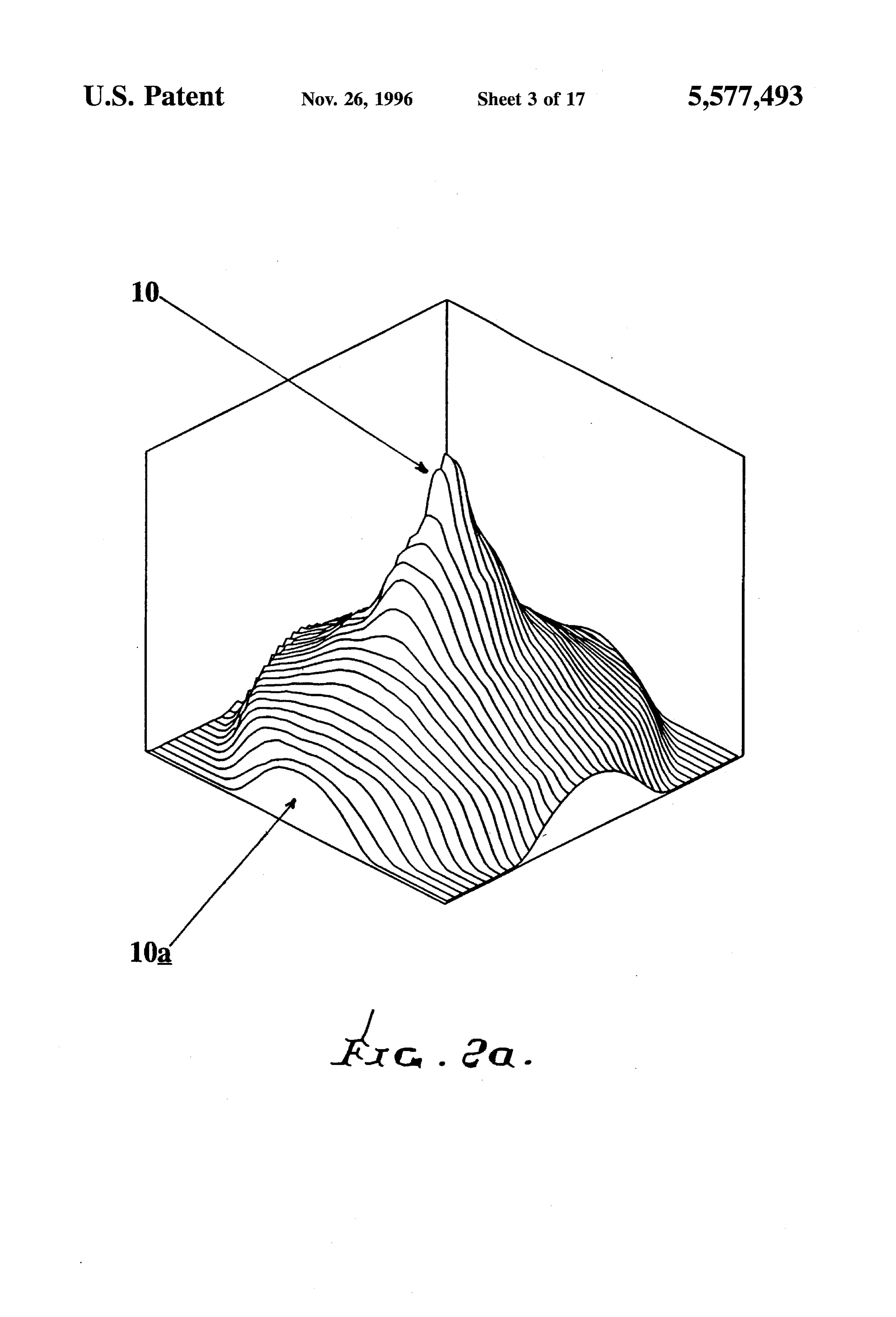
AUXLIARY LENS TO MODIFY THE FIG. 2 is a contour map and a corresponding three OUTPUT FLUX DISTRIBUTION OF A TIR dimensional isometric plot in FIG. 2a of the highly non LENS uniform flux density just above the TIR lens in FIG. 1 (i.e., at the exit side), as generated by a Monte-Carlo ray-trace
BACKGROUND OF THE INVENTION computer simulation;
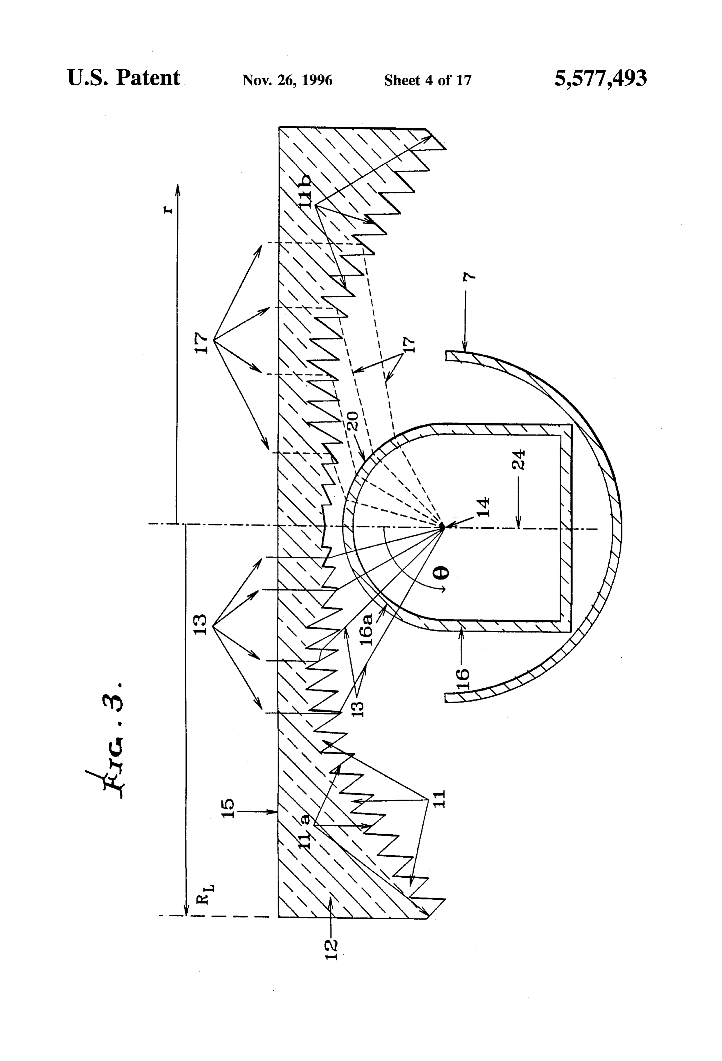
This application is a continuation-in-part of Ser. No. FIG. 3 is a diagram, in section, showing the r(0) mapping 07/869,003 filed Apr. 16, 1992 U.S. Pat. No. 5,404,869, Apr. requirement of a TIR lens in combination with a thin light 11, 1995. deviator in the light path between a light source and the-TIR This invention relates generally to radiant, particularly 10 lens;
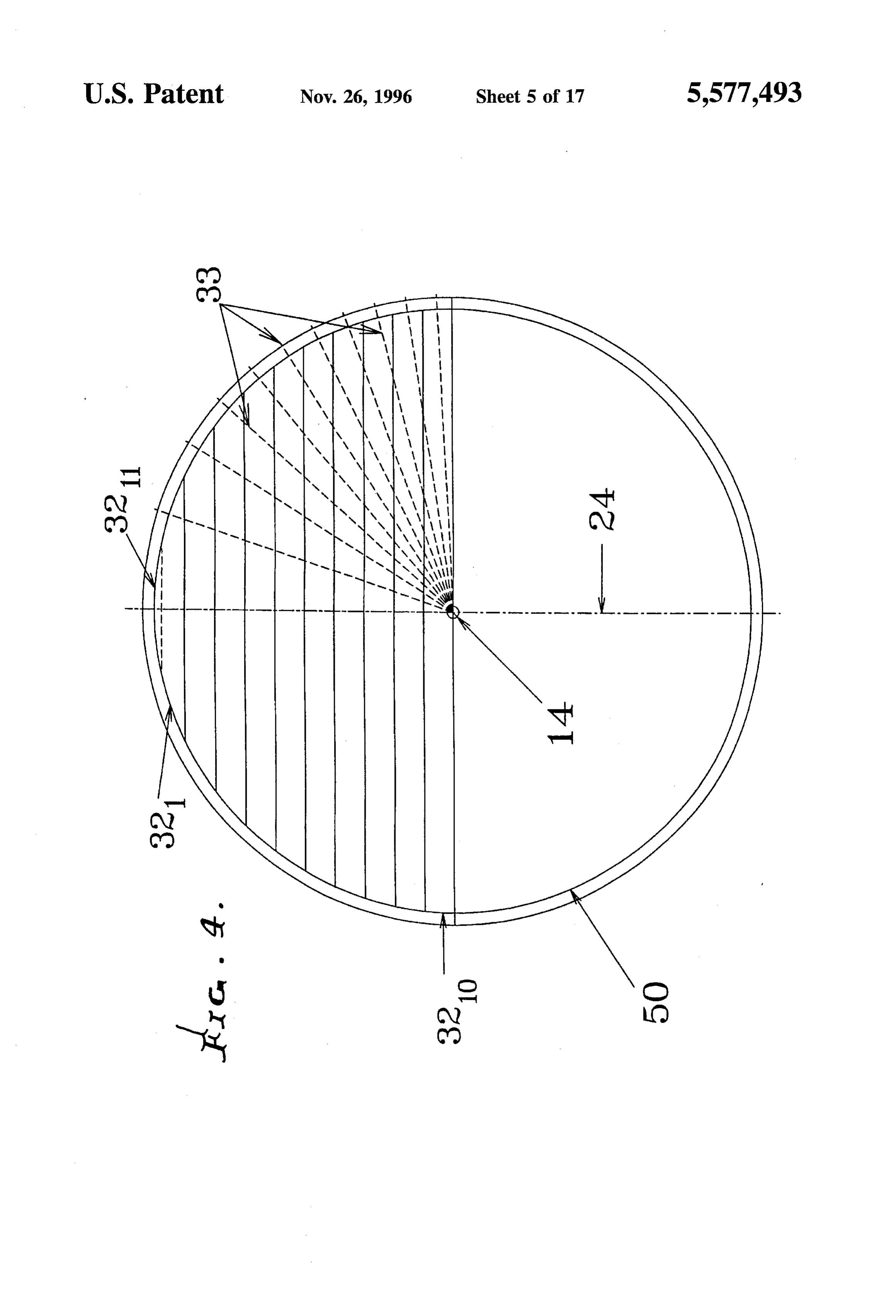
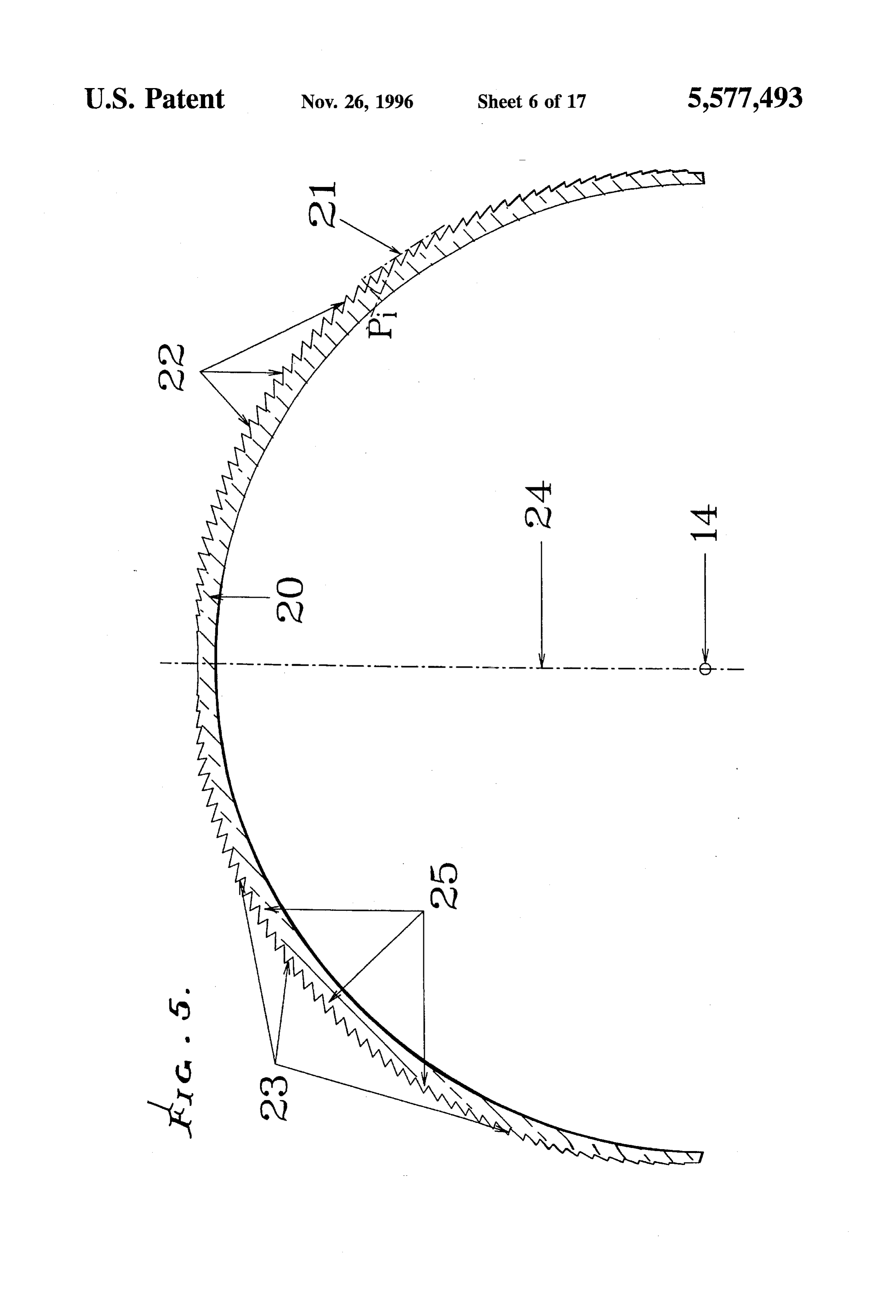
electromagnetic, energy concentration, redirection, and FIG. 4 is a diagram showing the preferred method of manipulation, and improves over the subject matter of U.S. measuring the intensity function I(0) of the combination of Pat. No. 4,337,759. It more particularly concerns apparatus source and reflector, and method for employing a transparent lens means with FIG. 5 is the cross-section of a hemispherical, Fresnel elements thereof using Total Internal Reflection (TIR). 15 type, light-deviating lens;
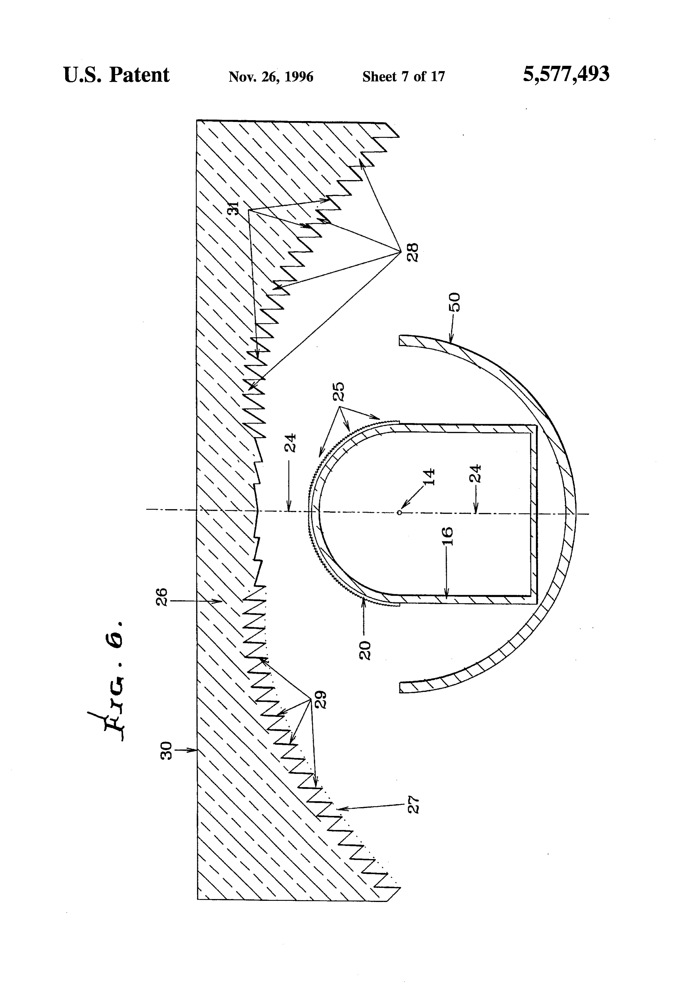
Because of its low aspect ratio, the TIR lens exhibits FIG. 6 is a section showing use of the FIG. 5 Fresnel lens strong coma, an aberration arising from the different dis as a light deviator, in combination with a TIR lens and tances from the light source of the various facets of the lens. reimaging reflector;
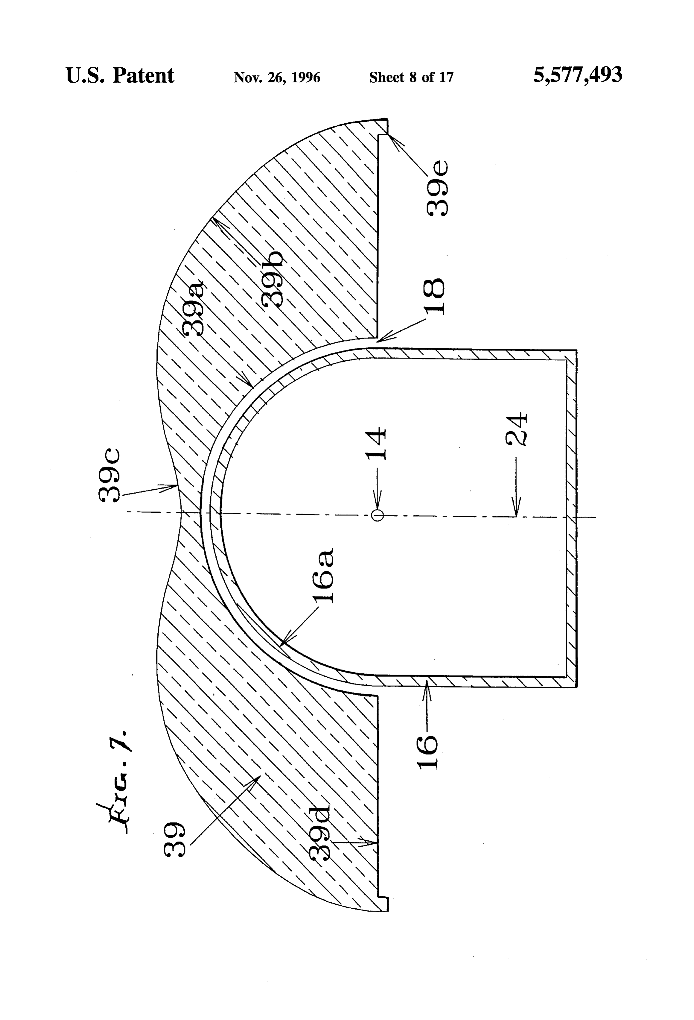
That is, the central part of the lens is so much closer to the FIG. 7 is a cross section of an incandescent lamp with source that its light output has wider angular divergence than 20 compact source and its associated light-deviation mushroom light coming from the edge of the lens. This causes the flux lens;
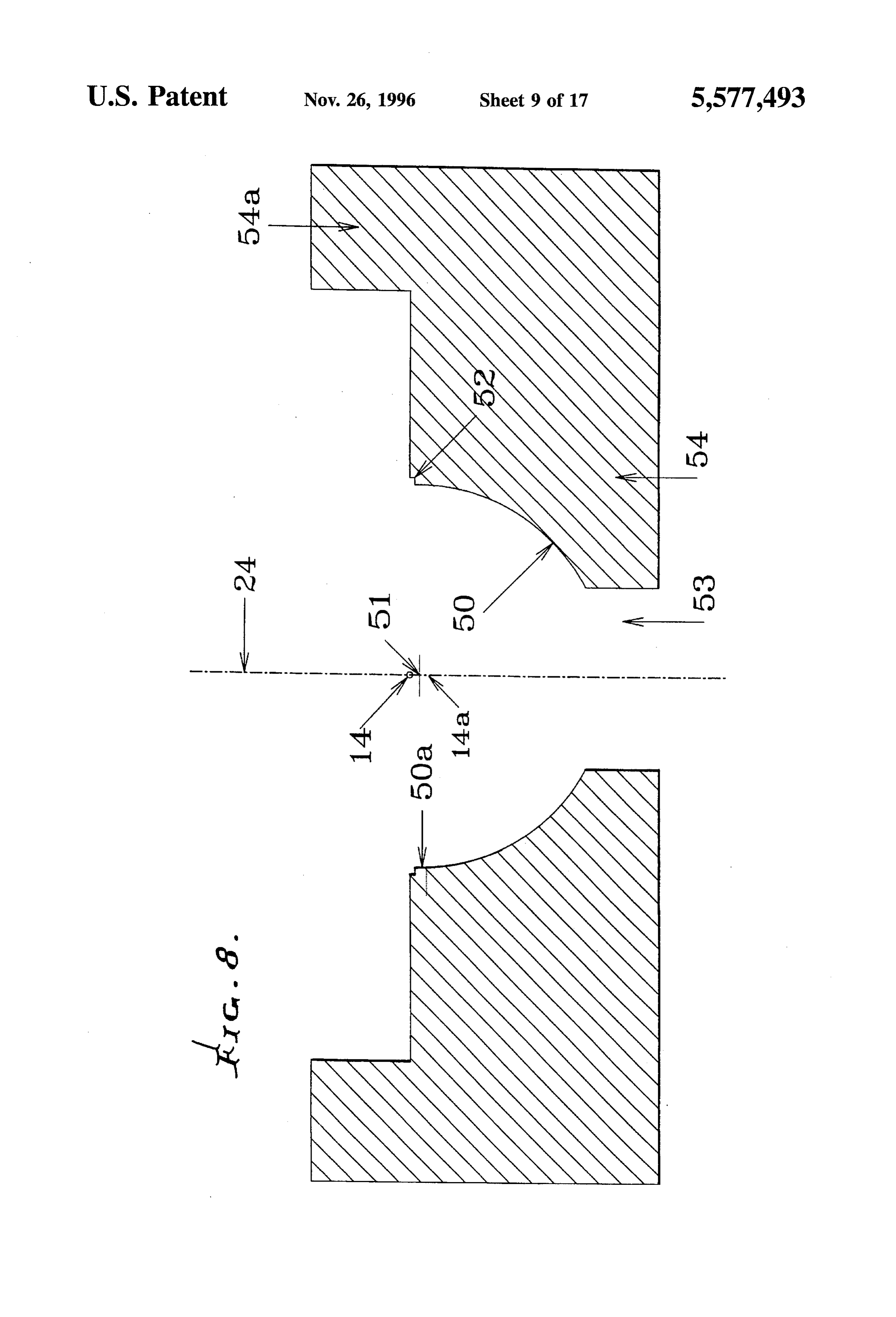
at the center of the lens to be much higher than that at the FIG. 8 is a cross section of a reimaging hemispherical edge, approximately in inverse proportion to the square of reflector, the distance of a facet from the source. Thus, the flux at the FIG. 9 is a cross section of a TIR lens designed for use in center of the lens can be over five times higher than at the 25 conjunction with a mushroom deviator lens; edge.
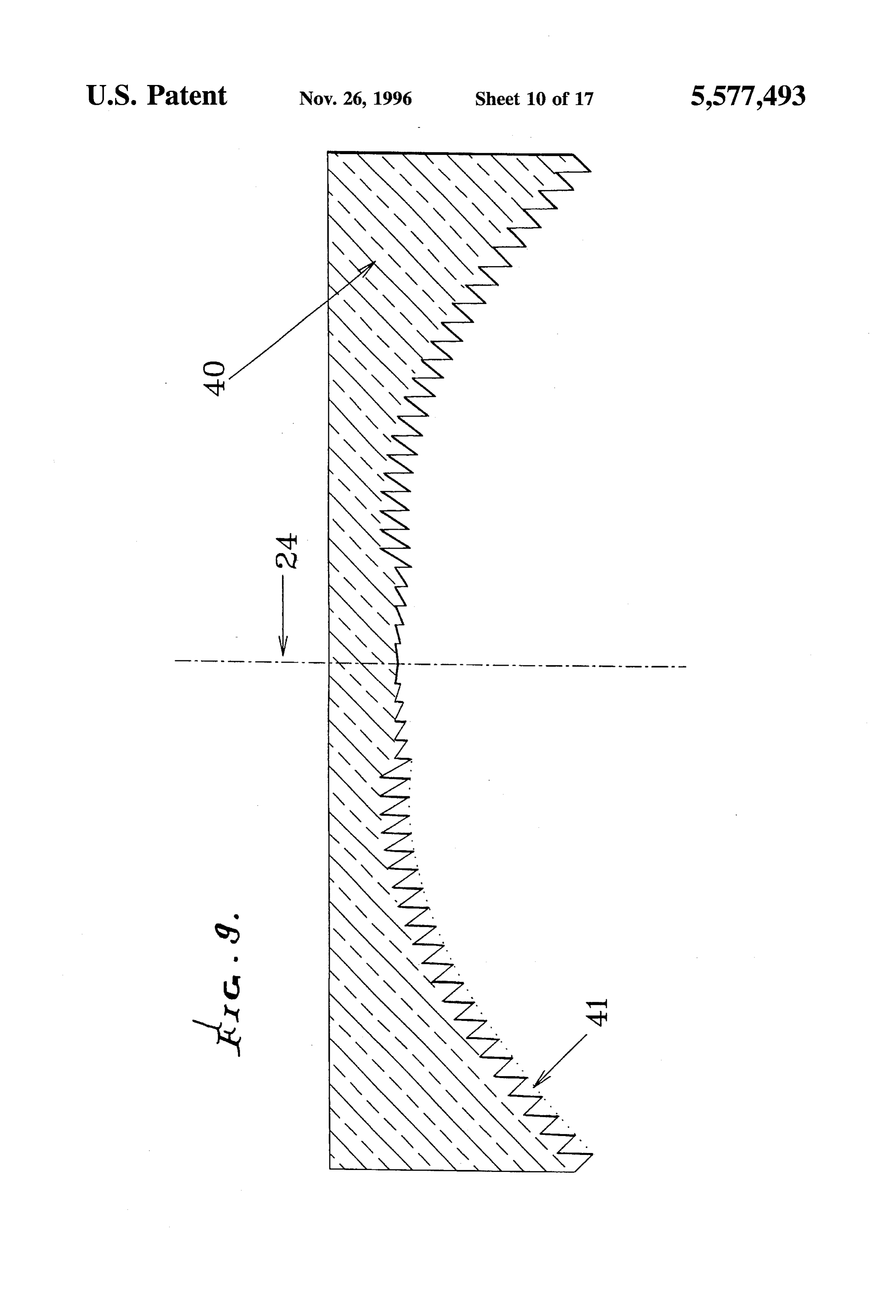
FIG. 10 is a cross section of the combination of mush
In some applications, such non-uniformity makes the TIR room lens, hemispherical reimaging reflector, and a modi lens less desirable, in spite of its compactness and efficiency.
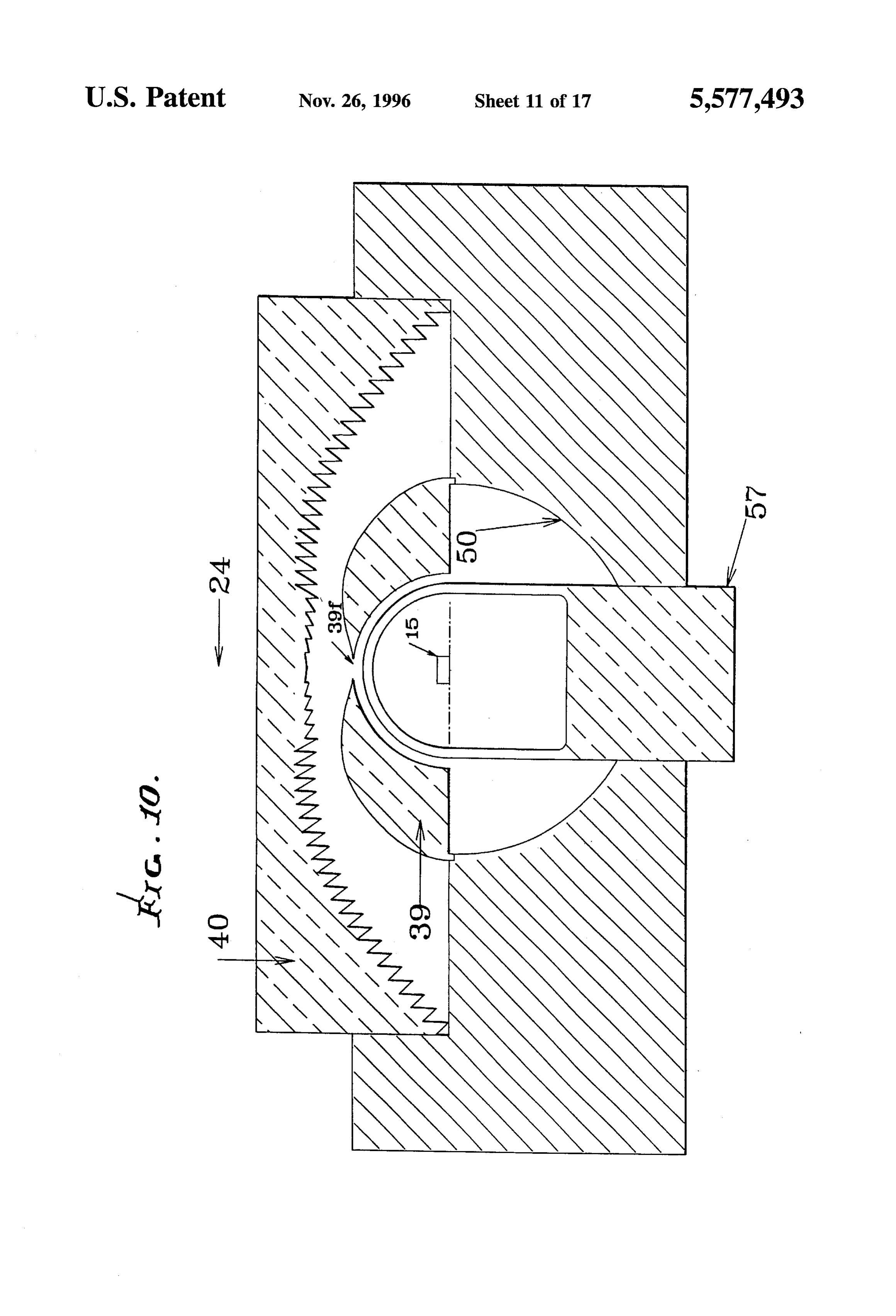
Backlighting of liquid crystal displays is a prominent fied collimating TIR lens;
example. What is needed is a way to magnify the image of 30 FIG. 11 is a diagram showing the combination of FIG. 10 the source for sideways directions (i.e., towards the rim of with diffusers and a liquid crystal display; the TER lens), while demagnifying it for upward directions FIG. 12 is a cross-section of a multi-section reimaging (i.e., along the axis of symmetry of the TIR lens). Conven reflector;
tional optical design methods are inapplicable to this prob FIG. 13 is a cross-section of an aspheric reimaging lem, since they deal with image formation; whereas, the TIR 35 reflector;
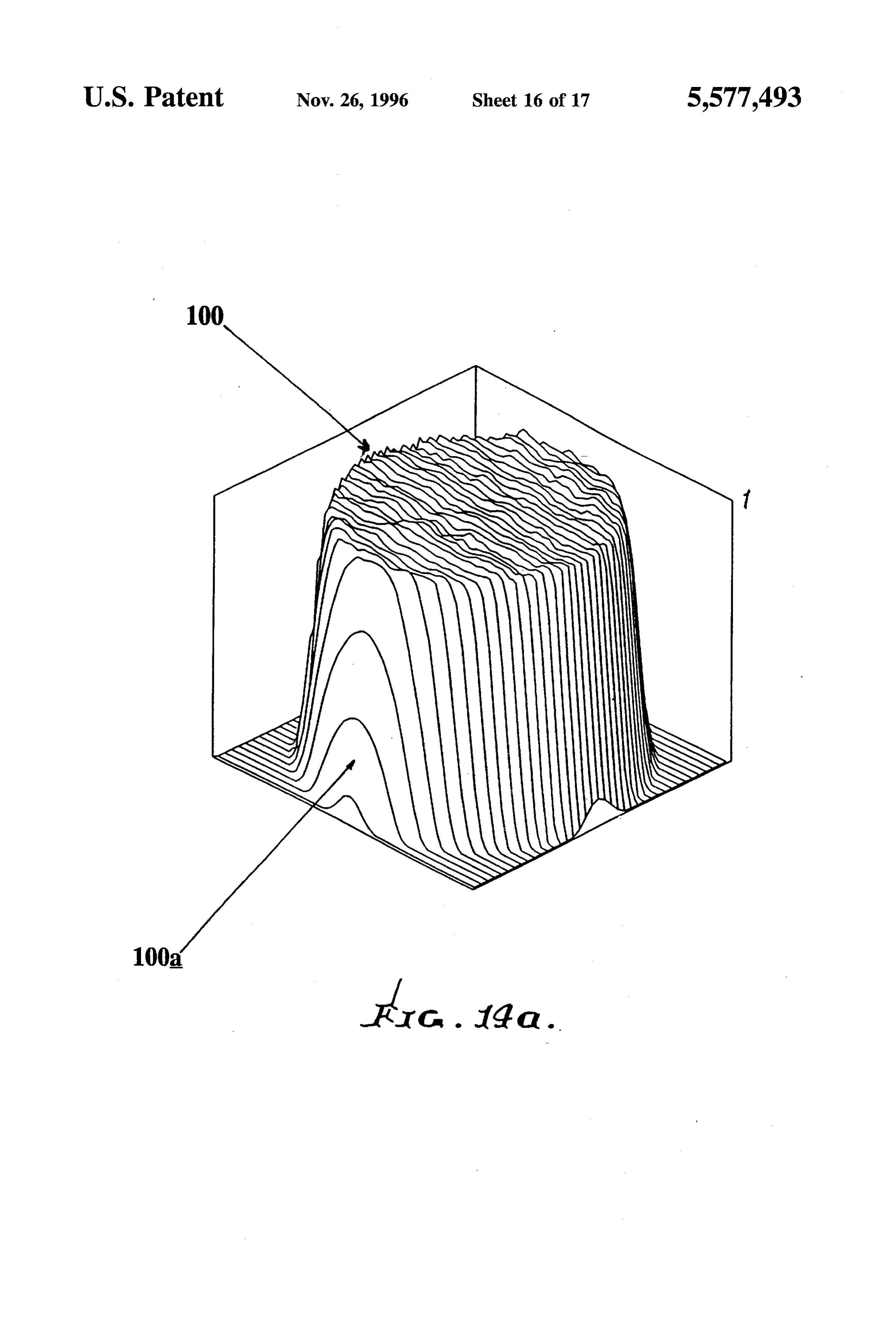
lens is a non-imaging device. This is an illumination prob FIG. 14 is a flux contour map of the light flux desity above lem, not an image-forming one. The nonuniformity can be TIR lens 40 an FIG. 14a is the corresponding three-dimen reduced, but not eliminated, by using a narrow cylindrical sional plot of this flux density;
SOCC.
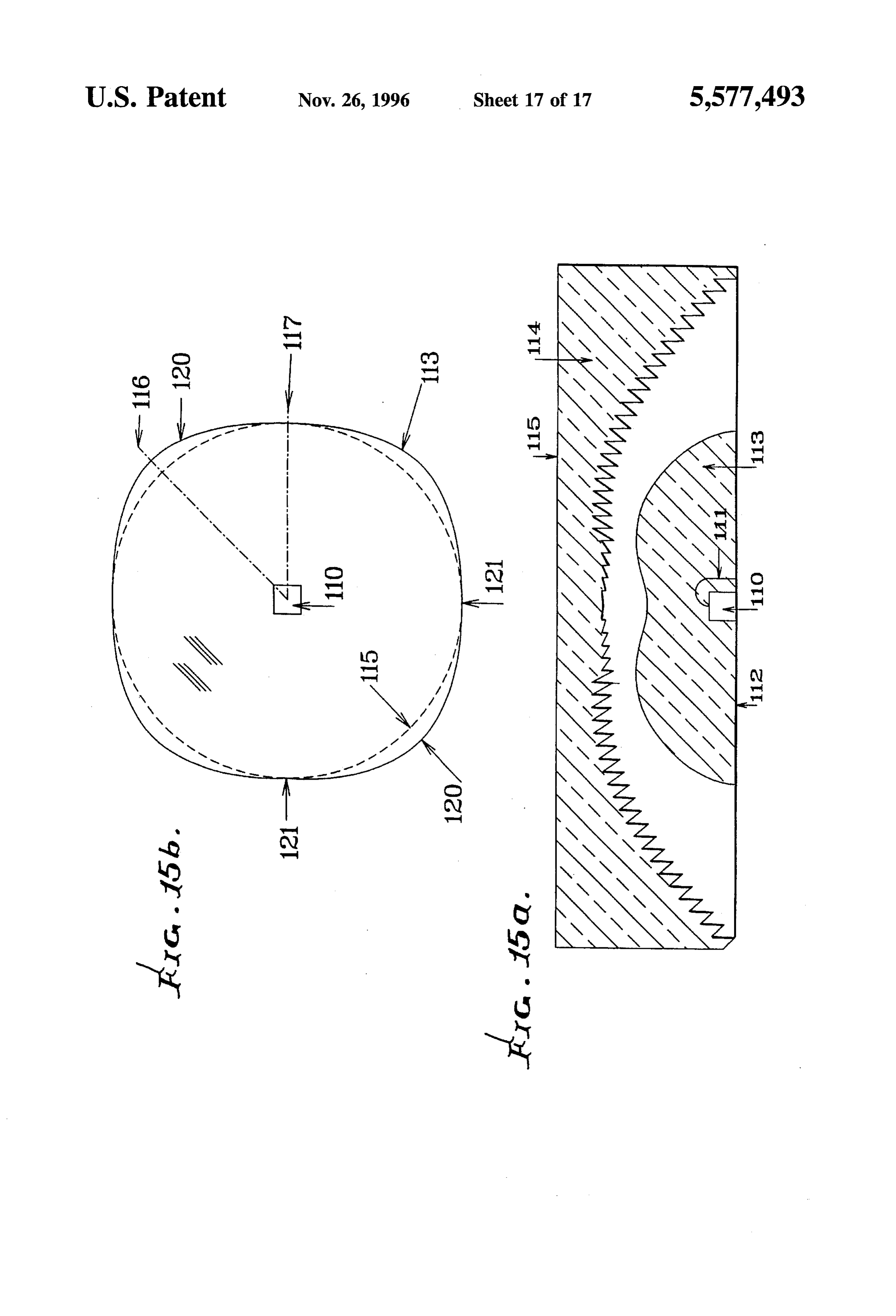
FIG. 15a is a cross-section and 15b a plan view of a
SUMMARY OF THE INVENTION mushroom lens for a light-emitting diode. It is a major object of the invention to provide a solution DETAILED DESCRIPTION to the above difficulties. Basically, the invention is embodied FIG. 1 shows a typical TIR lens 1 collimating the flux 2 in a combination that includes: from isotropic point source 3 onto screen 4. For the sake of
a) a TIR lens having a central axis, and toward which light clarity only the right half of the source's rays are shown. The from a light source is to be directed, and rays 5 coming out the center of the lens are closer together b) a light ray deviator positioned along the path of light than rays 6 at the outer edge region, indicating higher flux travel between the source and the TIR lens, for devi levels near the center than at the edges. Reflector 7 below ating light rays toward portions of the lens spaced from 50 source 3 sends downward rays 8 to the left side of the lens, the axis, thereby to more evenly distribute light flux at in effect reimaging the source.
the TIR lens. FIG. 2 and FIG. 2a show the results of a computer As will be seen, the deviator is typically a smooth simulation ray trace through the lens and reflector of FIG. 1. refractor lens having dome shape toward the TIR lens, but This simulation utilizes the Monte Carlo method, whereby a alternatively may be an externally faceted Fresnel lens. 55 large number of rays are sent in random directions and The invention is usable with displays, such as liquid traced through reflector and TIR lens to the screen. The crystal displays, and enhances their practicality by enabling resulting distribution of ray hits on the screen is used to incandescent light sources to provide uniform brightness. generate FIG. 2. On the left in FIG. 2 is a contour map of a These and other objects and advantages of the invention, computerized ray trace deriving the highly non-uniform as well as the details of an illustrative embodiment, will be 60 light flux density just above lens 1, with relative density more fully understood from the following specification and levels as labeled. On the right in FIG. 2a is the correspond drawings, in which: ing three-dimensional plot of this flux density. There is a
DRAWING DESCRIPTION
prominent central hot spot 10, with steady fall off of light flux per unit area toward the dimly illuminated edges at 10a
FIG.1 is a diagram showing a TIR lens, and auxiliary 65 of the contour plot.
reimaging reflector, collimating light from an isotropic point In accordance with the present invention, provision is source of light, but with nonuniform output; made to alleviate or eliminate this variable light flux per unit
Page 20
area by matching the light source's angular variations in The same intensity-mapping method can be used to output with corresponding locations on the TIR lens, in generate some desired non-uniform illumination profile I(r), effect spreading the light out from the peak until a flat by specifying its cumulative integral J(r) (see (4) below) and distribution is achieved. inverting it to obtain the function r(J). These operations Referring to FIG. 3, which illustrates the design method would typically be done numerically, with r(0)=r J(0)) ology of this invention, uniform light flux output at the exit implemented as a lookup table in a computer program that face 15 of TIR lens 12 (having radius R) means that the designs the combination of TIR lens and mushroom lens. fractional flux exiting the lens within a circle of radius r is The function J(r) is defined from I(r) as: simply (r/R). On the other hand, the light coming out r (4) isotropic (uniform in solid angle) source 14 into a cone 10 (x) X dx shaped solid angle with an apex angle 0 has a fractional flux 0 of (1-cos0). Actually, this is true only for the combination of source 14 and retroreflector 7 below source 14. This .
combination radiates light upward into the angular range
OsOs90°, which a TIR lens collects and collimates, e being 15 24,Inand the above, r is the radial distance of a facet from axis x is a customary dummy variable of spatial integra measured from source 14.
To match the isotropic source with a uniformly emitting tion. Most light sources are close enough to isotropic that the TIR lens, a ray emanating from source 14 at an angle 0 (0 deviation of rays at 0 to the facet at r(0) can be done by to 90) from axis 24 must be bent outward so that it goes to 20 arefraction.
thin lens
Two ways to accomplish this include use of either or a thick lens. Since it is analytically easier to a facet at radial location given by derive a thin, or Fresnelized version, this will be done first. r=Riv(1-cos0) with Osrs R. (l) For a thin hemispherical Fresnel lens of radius R cen tered upon light source 14, a ray at angle 0 must be deviated
For a non-isotropic source having angularly variable inten to the angle O, given by sity I(e), the integrated relative intensity J(0) varies 25 r(0) - Risin(0) (5) between 0 at 0=0 and 1 at 0=90° and is given by or = tan
0 (2) where Z(0) is the height of the TIR lens facet at r(0). In an I(d) sin(D) dop actual lens design, a trial profile Z(r) is used to generate a TL2 30 corresponding deviator lens, then a new profile is generated I(d) sin(d) did from this deviator lens. Then a new deviator lens is gener O ated for this new profile. Repeating this iteration, another where d is a customary dummy variable of angular inte TIR lens profile is generated, until the TIR lens and the gration. deviator lens are matched. Usually three iterations are suf ficient. Referring to FIG. 6, profile 27 is appropriate for
FIG. 4 shows how the intensity distribution I(G) of a lamp 35 deviator and reflector would be measured. Collector hemisphere 32, lens 20 when the rays from the deviator enter the of radius R, is divided into sections 32 to 32 of equal entry faces 29 and fully illuminate TIR faces 31, but with no area, and covers source 14 and reflector 50, so as to collect light lost to leakage over the top of the TIR faces. Because all their light output. In order to measure the intensity 40 the deviator lens makes the rays appear to come from a virtual source that is above the real source, the TIR lens distribution I(G) as a function of equal solid angles, N profile 27 is raised.
sections shown need only have equal height R/N to ensure The required tilt angle P of each Fresnel facet on the they all have the same interior surface area. The total light hemispheric deviator lens is given by I received by section i, having specific angles 0, as shown by the radial dashed lines 33, is an approximation to I(0). (6) The accuracy of the approximation increases with the num 45 sin(0) ( 1 + -in - 1- - nsin(o)
ber of sections. With a non-homogeneous source, the aver P(0) = 0 - tanl age direction B, of light received by collector section i will cos(0) ( 1 + ) - cos(O)
differ somewhat from 0, and would be used in its place in the analysis below. There is, however, a complication with 50 where n is the refractive index of the material of the deviator section 32, in that its inclusion about central axis 24 would lens. The rays at 0=0 and 0=TL/2 (90) are already going to cause it to integrate out the intensity information for direc their proper radii, r=0 and R, so that P=0 for them. tion 0. Accordingly, there must be a small polar section FIG. 5 shows the profile of a Fresnel deviator lens 20 that 32, to measure the intensity in the direction of axis 24. maps the output of an isotropic source 14 to uniform TIR Light emitted at an angle e must be deviated to radius r(0) 55 lens output. The lens extends hemispherically about axis 24. at exit face 15 of TIR lens 12, where: Fresnel facets 25 extend annularly about axis 24, with refracting faces 22 of facet number i making the angle P.
(3) with tangent 21; whereas, faces 23 are radially oriented so as to minimally interfere with light from the source at
Note that in FIG. 3, the facets 11 of the TIR lens 12 have hemisphere center 14. Note that, if this Fresnel deviator lens surfaces 11a angled relative to axis 24 to collimate the 60 was to be manufactured by a molding process, either a undeviated rays 13 from source 14 that pass radially through splitting mold would be necessary for a rigid lens material, the source envelope 16, whose dome wall 16a extends or the lens material must be elastomeric, such as optical hemispherically about source 14. A new set of facets with silicone.
angled surfaces 11b, on a somewhat higher profile (not FIG. 6 shows this Fresnel deviator lens 20, along with its shown here, but detailed in FIG. 6), is required to collimate 65 associated TIR lens 26, which has a higher profile 27 than the deviated rays 17 refracted by Fresnel-lens deviator 20 the TIR lens in FIG. 3, and, consequently, TIR faces 31, (FIG. 5) situated on the exterior of dome wall 16a. correspond to faces 11b in FIG.3, are differently angled than
Page 21
TIR faces 11a of collimating TIR lens 12 in FIG. 3. It is of the TIR lens. A second diffuser 61 spatially integrates this desirable that the TIR lens have numerous small facets 27, blurring, so that the TIR lens facets are not visible to viewers having entry faces 29 and (in this case) common flat exit of the LCD.
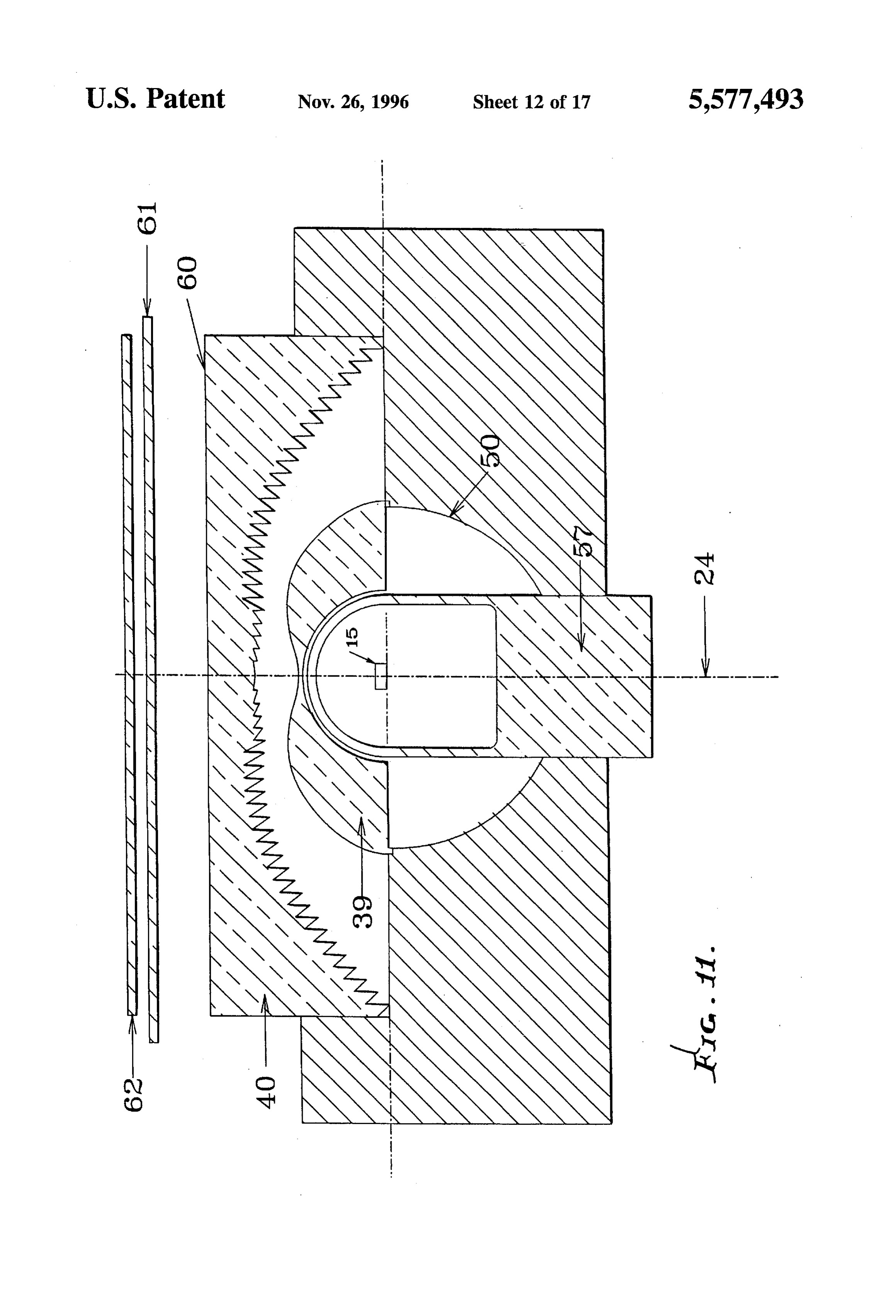
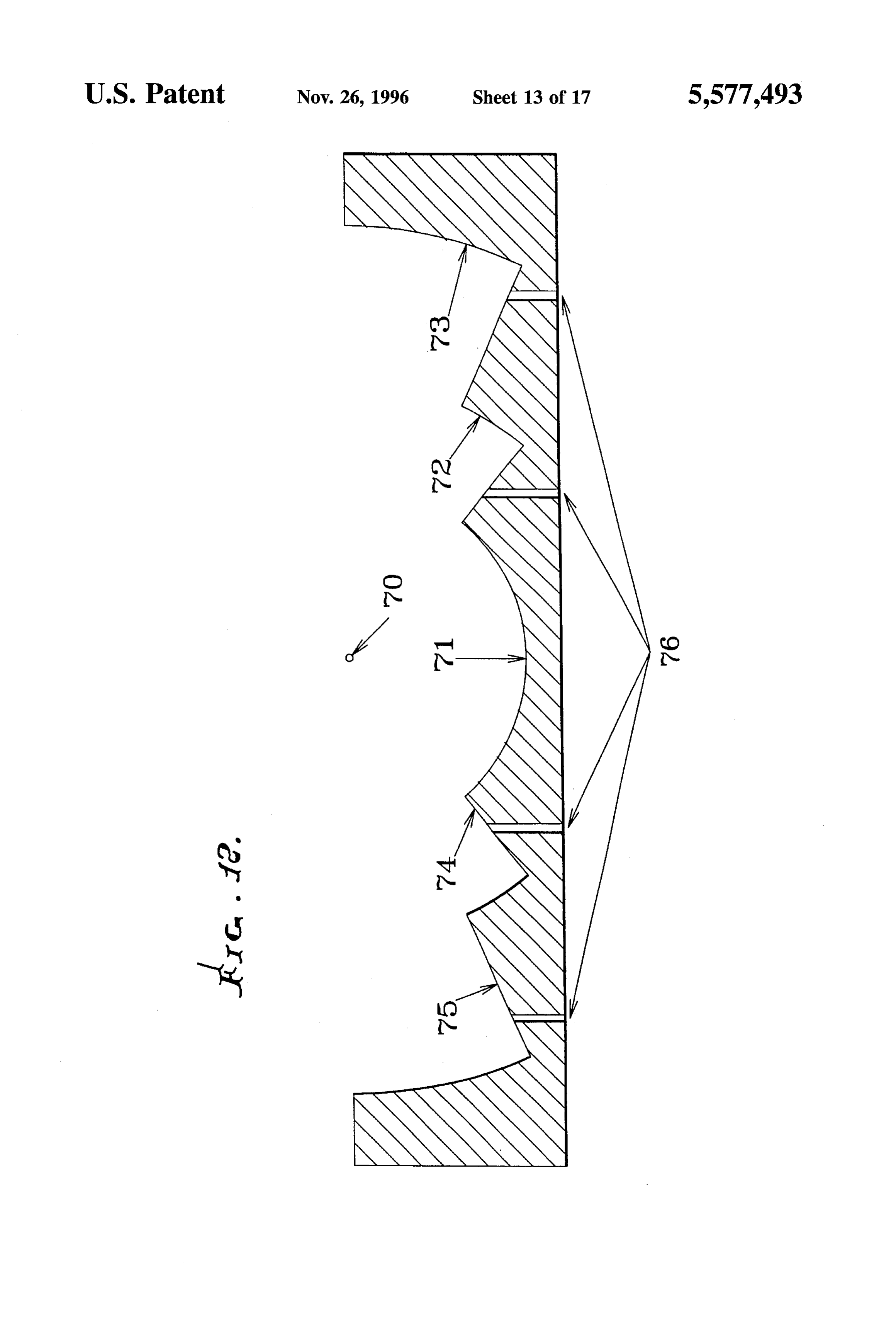
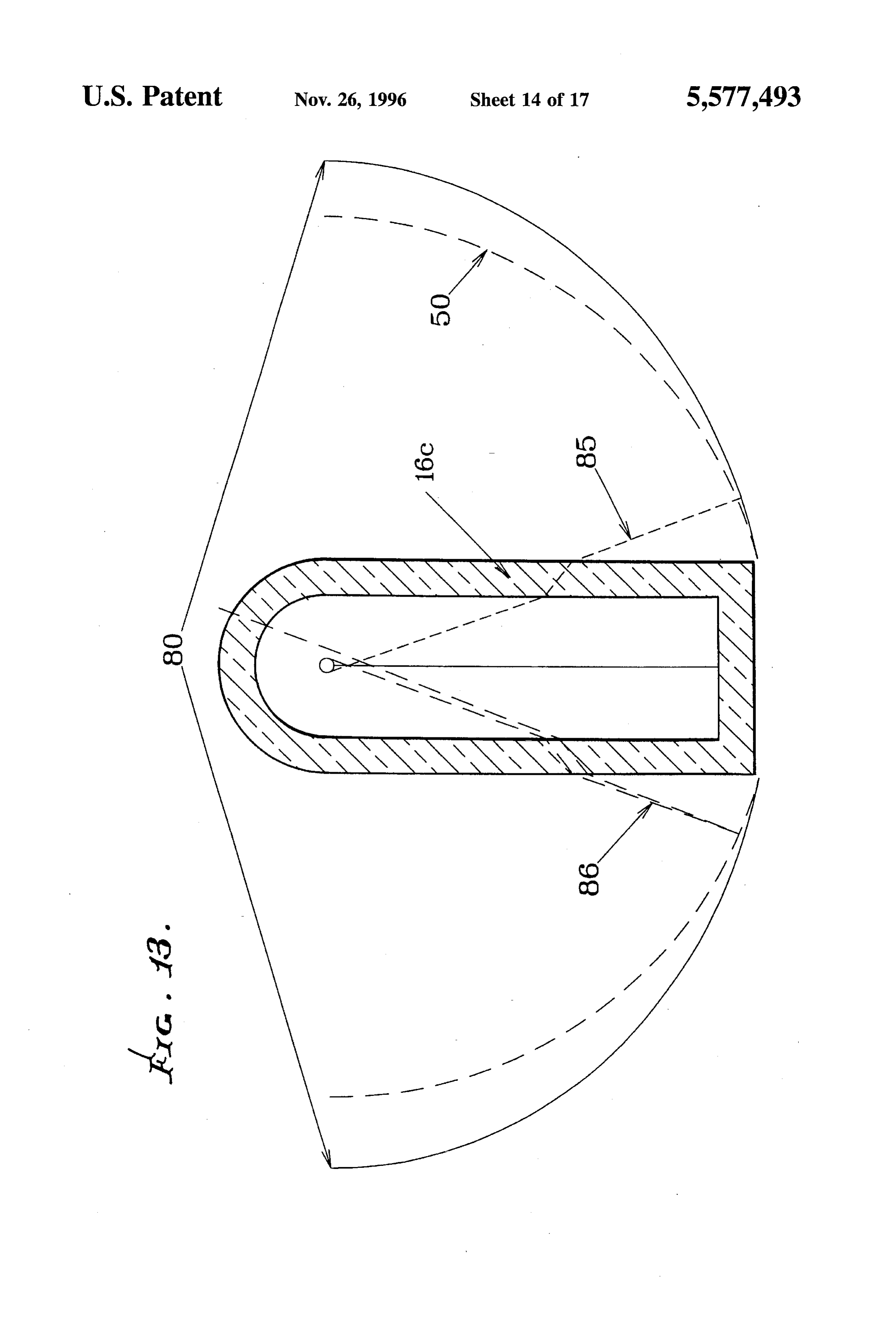
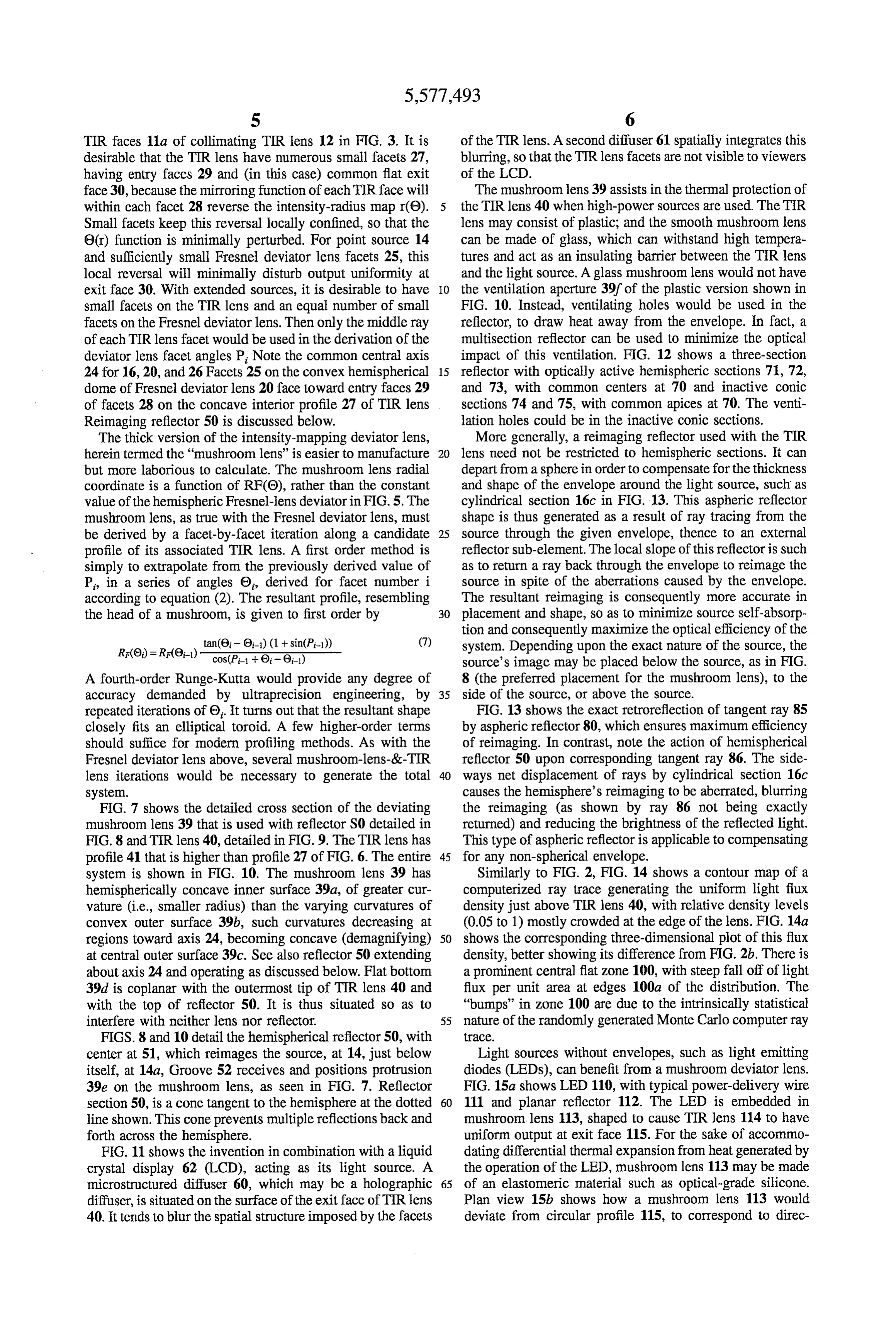
face 30, because the mirroring function of each TIR face will The mushroom lens 39 assists in the thermal protection of within each facet 28 reverse the intensity-radius map r(0). the TIR lens 40 when high-power sources are used. The TIR Small facets keep this reversal locally confined, so that the lens may consist of plastic; and the smooth mushroom lens 0(r) function is minimally perturbed. For point source 14 can be made of glass, which can withstand high tempera and sufficiently small Fresnel deviator lens facets 25, this tures and act as an insulating barrier between the TIR lens local reversal will minimally disturb output uniformity at and the light source. A glass mushroom lens would not have exit face 30. With extended sources, it is desirable to have O the ventilation aperture 39f of the plastic version shown in small facets on the TIR lens and an equal number of small FIG. 10. Instead, ventilating holes would be used in the facets on the Fresnel deviator lens. Then only the middle ray reflector, to draw heat away from the envelope. In fact, a of each TIR lens facet would be used in the derivation of the multisection reflector can be used to minimize the optical deviator lens facet angles P. Note the common central axis impact of this ventilation. FIG. 12 shows a three-section 24 for 16, 20, and 26 Facets 25 on the convex hemispherical 15 reflector with optically active hemispheric sections 71, 72, dome of Fresnel deviator lens 20 face toward entry faces 29 and 73, with common centers at 70 and inactive conic of facets 28 on the concave interior profile 27 of TIR lens sections 74 and 75, with common apices at 70. The venti Reimaging reflector 50 is discussed below. lation holes could be in the inactive conic sections. The thick version of the intensity-mapping deviator lens, More generally, a reimaging reflector used with the TIR herein termed the "mushroom lens' is easier to manufacture 20 lens need not be restricted to hemispheric sections. It can but more laborious to calculate. The mushroom lens radial depart from a sphere in order to compensate for the thickness coordinate is a function of RF(0), rather than the constant and shape of the envelope around the light source, such as value of the hemispheric Fresnel-lens deviatorin FIG.5. The cylindrical section 16c in FIG. 13. This aspheric reflector mushroom lens, as true with the Fresnel deviator lens, must shape is thus generated as a result of ray tracing from the be derived by a facet-by-facet iteration along a candidate 25 source through the given envelope, thence to an external profile of its associated TIR lens. A first order method is reflector sub-element. The local slope of this reflector is such simply to extrapolate from the previously derived value of as to return a ray back through the envelope to reimage the P, in a series of angles 0, derived for facet number i source in spite of the aberrations caused by the envelope. according to equation (2). The resultant profile, resembling The resultant reimaging is consequently more accurate in the head of a mushroom, is given to first order by 30 placement and shape, so as to minimize source self-absorp tion and consequently maximize the optical efficiency of the tan(0-0) (1 + sin(P-1)) (7) system. Depending upon the exact nature of the source, the
source's image may be placed below the source, as in FIG.
A fourth-order Runge-Kutta would provide any degree of 8 (the preferred placement for the mushroom lens), to the accuracy demanded by ultraprecision engineering, by 35 side of the source, or above the source.
repeated iterations of 0. It turns out that the resultant shape FIG. 13 shows the exact retroreflection of tangent ray 85 closely fits an elliptical toroid. A few higher-order terms by aspheric reflector 80, which ensures maximum efficiency should suffice for modern profiling methods. As with the of reimaging. In contrast, note the action of hemispherical Fresnel deviator lens above, several mushroom-lens-&-TIR reflector 50 upon corresponding tangent ray 86. The side lens iterations would be necessary to generate the total 40 ways net displacement of rays by cylindrical section 16c system. causes the hemisphere's reimaging to be aberrated, blurring FIG. 7 shows the detailed cross section of the deviating the reimaging (as shown by ray 86 not being exactly mushroom lens 39 that is used with reflector S0 detailed in returned) and reducing the brightness of the reflected light. FIG. 8 and TIR lens 40, detailed in FIG. 9. The TIR lens has This type of aspheric reflector is applicable to compensating profile 41 that is higher than profile 27 of FIG. 6. The entire 45 for any non-spherical envelope.
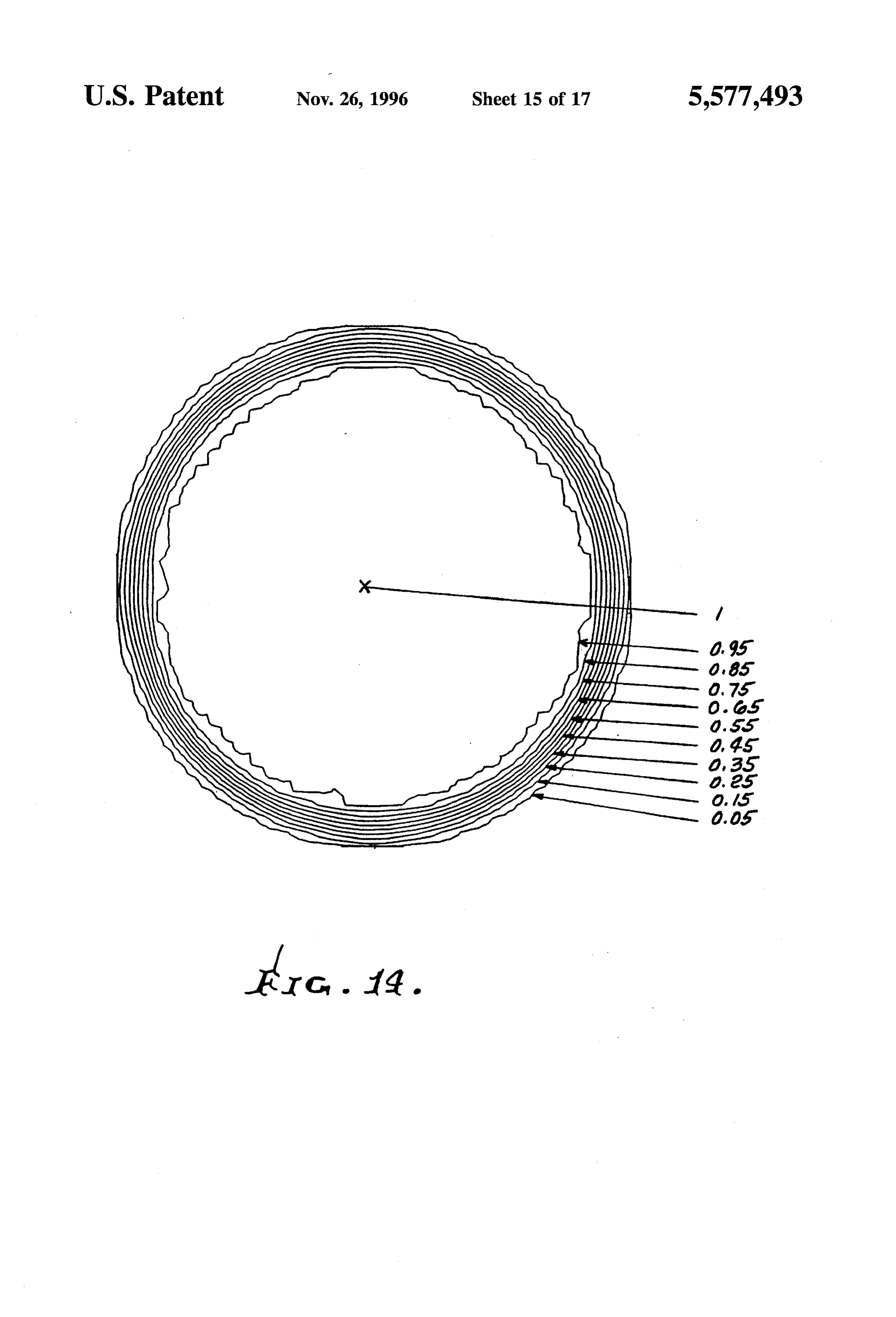
system is shown in FIG. 10. The mushroom lens 39 has Similarly to FIG. 2, FIG. 14 shows a contour map of a hemispherically concave inner surface 39a, of greater cur computerized ray trace generating the uniform light flux vature (i.e., smaller radius) than the varying curvatures of density just above TIR lens 40, with relative density levels convex outer surface 39b, such curvatures decreasing at (0.05 to 1) mostly crowded at the edge of the lens. FIG. 14a regions toward axis 24, becoming concave (demagnifying) 50 shows the corresponding three-dimensional plot of this flux at central outer surface 39c. See also reflector 50 extending density, better showing its difference from FIG. 2b. There is about axis 24 and operating as discussed below. Flatbottom a prominent central flat zone 100, with steep fall off of light 39d is coplanar with the outermost tip of TIR lens 40 and flux per unit area at edges 100a of the distribution. The with the top of reflector 50. It is thus situated so as to "bumps' in zone 100 are due to the intrinsically statistical interfere with neither lens nor reflector. 55 nature of the randomly generated Monte Carlo computer ray FIGS. 8 and 10 detail the hemispherical reflector 50, with trace.
center at 51, which reimages the source, at 14, just below Light sources without envelopes, such as light emitting itself, at 14a, Groove 52 receives and positions protrusion diodes (LEDs), can benefit from a mushroom deviator lens. 39e on the mushroom lens, as seen in FIG. 7. Reflector FIG. 15a shows LED 110, with typical power-delivery wire section 50, is a cone tangent to the hemisphere at the dotted 60 111 and planar reflector 112. The LED is embedded in line shown. This cone prevents multiple reflections back and mushroom lens 113, shaped to cause TIR lens 114 to have forth across the hemisphere. uniform output at exit face 115. For the sake of accommo FIG. 11 shows the invention in combination with a liquid dating differential thermal expansion from heat generated by crystal display 62 (LCD), acting as its light source. A the operation of the LED, mushroom lens 113 may be made microstructured diffuser 60, which may be a holographic 65 of an elastomeric material such as optical-grade silicone. diffuser, is situated on the surface of the exit face of TIR lens Plan view 15b shows how a mushroom lens 113 would 40. It tends to blur the spatial structure imposed by the facets deviate from circular profile 115, to correspond to direc
Page 22
tional differences in a light source. LEDs typically have the 8. The combination of claim 7 wherein the deviator is a shape of a cube, so that their output is greater in the direction Fresnel lens.
116 of the cube diagonal than in the direction 117 perpen 9. The combination of claim 8 wherein the deviator and dicular to the cube face. To compensate, the mushroom lens the TIR lens have a common central axis, and the TIR lens may have somewhat different cross sections in these two has facets facing toward the deviator, and the deviator has directions, as seen in FIG. 15b. Note corresponding greater Fresnel lens facets facing toward the TIR lens. and lesser curvatures about the central axis, at 120 and 121. 10. The combination of claim 9 wherein the TIR lens This methodology may be utilized in any source with facets are equal in number with the Fresnel lens facets. angular intensity I(0, d) that is a function of horizontal 11. In combination angle d in the plane of the TIR lens. The collector hemi 10 a) a TIR lens having a central axis, and toward which light sphere 32 of FIG. 4 would be subdivided into a sufficiently from a light source is to be directed, and large number of gores as to accurately assess the d variation b) a light ray deviator positioned along the path of light
In summary, the mushroom-shaped, light-deviating lens is travel between said source and the TIR lens, for devi a powerful new way to control the output of a TIR lens. ating light rays toward portions of the lens spaced from Improved collimation is provided because the entire beam 15 said axis, thereby to more evenly distribute light flux at will have the same angular spread, resulting in improved the output of said TIR lens, beam propagation over conventional parabolic reflectors, c) and wherein the dome shape of the deviator is hemi which have very non-uniform output. This allows the use of spherical.
holographic diffusers and lenticular lenslet arrays to produce 12. In combination tailored output intensity, because the uniform input from the 20 a) a TIR lens having a central axis, and toward which light TIR lens is crucial to the use of these devices, which can be from a light source is to be directed, and made integral with the output face of the TIR lens. This b) a light ray deviator positioned along the path of light enables compact LED light sources with specifically tailored travel between said source and the TIR lens, for devi output to be available for automobile tail-lights and both ating light rays toward portions of the lens spaced from small and large electronically controlled message signs. 25 said axis, thereby to more evenly distribute light flux at We claim: the output of said TIR lens, 1. In combination c) and wherein the deviator has mushroom profile. a) a TIR lens having a central axis, and toward which light 13. The combination of claim 12 including a ventilation hole in the mushroom deviator.
from a light source is to be directed, and 14. The combination of claim 12 wherein the deviator is b) a light ray deviator positioned along the path of light 30 a lens having an outer surface with said mushroom lens travel between said source and the TIR lens, for devi shape, and a concave inner surface of greater curvature than ating light rays toward portions of the lens spaced from curvature defined by said outer surface. said axis, thereby to more evenly distribute light flux at 15. The combination of claim 14 including a hemispheri the output of said TIR lens, 35 cally shaped reflector at the side of the deviator opposite the c) said deviator being a non-imaging optical element for TIR lens to receive light from said source and to reimage the transforming the cumulative angular distribution of source 16.
at a location between the source and said reflector.
The combination of claim 15 wherein the reflector has intensity of light from said source into a different distribution, which said TIR lens forms into a uniform an upper cone-shaped section located to prevent multiple beam. reflections back and forth across the hemispherical reflector. 2. The combination of claim I wherein said deviator is a 17. The combination of claim 12 wherein said light source light refractor. is a light emitting diode embedded in said deviator lens. 3. The combination of claim 1 wherein said TIR lens has 18. The combination of claim 17 wherein the light emit i) an entry face to receive incidence of light flux ting diode has a non-cylindrical shape, and the deviator
mushroom-shaped outer surface has alternating greater and ii) an exit face to pass light to the lens exterior, and lesser sequential curvatures in planes normal to said axis. iii) a Totally Internally Reflecting face angled relative to 19. The combination of claim 18 including a planar said entry and exit faces to redirect toward the exit face reflector at the bottom of the deviator to receive downward the light flux incident on said entry face. directed light from the light emitting diode and to reflect said 4. The combination of claim 1 including said source from 50 light upwards to the TIR lens.
which light is transmitted for incidence on said entry face. 20. The combination of claim 19 wherein the deviator has 5. The combination of claim 1 wherein said source and a hemispherical shape with an external Fresnel lens. deviator are positioned in such proximity to the TIR lens that 21. In combination light traveling from the TIR lens to the display is collimated. a) a TIR lens having a central axis, and toward which light 6. The combination of claim 1 wherein the TER lens from a light source is to be directed, and
consists of molded plastic material, and the deviator is a b) a light ray deviator positioned along the path of light glass lens. travel between said source and the TIR lens, for devi 7. In combination ating light rays toward portions of the lens spaced from a) a TIR lens having a central axis, and toward which light said axis, thereby to more evenly distribute light flux at from a light source is to be directed, and 60 the output of said TIR lens, b) a light ray deviator positioned along the path of light c) and including a reflector extending about said axis at travel between said source and the TIR lens, for devi the side of the deviator opposite the TIR lens to reflect ating light rays toward portions of the lens spaced from light from the source back toward the source. said axis, thereby to more evenly distribute light flux at 22. The combination of claim 21 including a ventilation the output of said TIR lens, 65 hole in the reflector.
c) and wherein said deviator has dome shape in a direction 23. The combination of claim 21 wherein the reflector has toward the TIR lens. multiple optically active hemispheric sections with common
Page 23
centers, with inactive conic sections, each of which is 27. In combination between two of the hemispheric sections, said conic sections a) a TIR lens having a central axis, and toward which light having common apices at the common centers of said from a light source is to be directed, and hemispheric sections.
24. The combination of claim 21 wherein the reflector is b) a light ray deviator positioned along the path of light aspherical for reimaging the source at a location adjacent to travel between said source and the TIR lens, for devi said source through a non-spherical envelope situated ating light rays toward portions of the lens spaced from between said source and said reflector. said axis, thereby to more evenly distribute light flux at 25. In combination the output of said TIR lens, a) a TIR lens having a central axis, and toward which light 10 c) and including said source from which light is trans from a light source is to be directed, and mitted for incidence on said entry face, b) a light ray deviator positioned along the path of light d) aliquid crystal display positioned to receive backlight travel between said source and the TIR lens, for devi ating light rays toward portions of the lens spaced from 5 ing from the TIR lens, said axis, thereby to more evenly distribute light flux at e) and including a light diffuser located between said TIR the output of said TIR lens, lens and said liquid crystal display. c) and including a liquid crystal display positioned to 28. In combination receive backlighting from the TIR lens. a) a TIR lens having a central axis, and toward which light 26. In combination from a light source is to be directed, and a) a TIR lens having a central axis, and toward which light b) a light ray deviator positioned along the path of light from a light source is to be directed, and travel between said source and the TIR lens, for devi b) a light ray deviator positioned along the path of light ating light rays toward portions of the lens spaced from travel between said source and the TIR lens, for devi said axis, thereby to more evenly distribute light flux at ating light rays toward portions of the lens spaced from 25 the output of said TIR lens, said axis, thereby to more evenly distribute light flux at the output of said TIR lens, c) and including said source from which light is trans c) and including said source from which light is trans mitted for incidence on said entry face, mitted for incidence on said entry face, d) and wherein said light source comprises an LED. d) and including a liquid crystal display positioned to 30 receive backlighting from the TIR lens. ck k : : :
Provenance
- Collection
- Patents citing this work
- Current assignee
- Innolux Corp
- Original assignee
- TIR Technologies Inc
- Pages
- 23
- Method
- pdftotext (the PDF's own text layer) + pdftoppm 300dpi page scans
- Patent office record
- patents.google.com →
- Source
- Google Patents citing-documents table
- Inventors
- William A. Parkyn, Jr.; David G. Pelka; TIR Technologies Inc
- Published
- 1996-11-26
- Transcribed from
- patentimages.storage.googleapis.com →