patent · US5501185A
Biogas-driven generator set
26 March 1996
Page 1 — bibliographic record
United States Patent (19) 11. Patent Number: 5,501,185 King et al. 45) Date of Patent: Mar. 26, 1996 54) BIOGAS-DRIVEN GENERATOR SET 4,218,328 8/1980 Vaughan ................................. 252A33.3 4,389,981 6/1983 Meyer ......................................... 12313
E75) Inventors: James L. King, Sheboygan; Timothy 4,437,813 3/1984 Ingram ...................................... 417/53 J. Mintner, Elkhart Lake, both of Wis. 4,568,473 2/1986 Theodore et al. ................. 252/51.5 R 4,697.553 10/1987 Lie ............................................ 123/73 4,750,454 6/1988 Santina et al. . ... 123/3 (73) Assignee: Kohler Co., Kohler, Wis. 4,774,909 10/1988 Doldever ............ 123/527 4,989,573 2/1991 Yokoyama et al. ... 123/527 21 Appl. No.: 369,623 5,027,758 7/1991 Siegler ............... ... 123/73 AD 5,034,114 7/1991 Kukin ..... ... 208/48 AA 22 Filed: Jan. 6, 1995 5,300,819 4/1994 Lee .............................................. 123/3 (51) Int. Cl6 - - - - -- - - - - - a a a a FO2B 43/04; FO2B 75/12; Primary Examiner-Erick R. Solis FO2M 21/04 Attorney, Agent, or Firm-Quarles & Brady 52 U.S. Cl. ...................... 123/73 AD; 123/527; 123/1 A 58 Field of Search ..................................... 123/527, 1A, 57 ABSTRACT 123/196R, 73 AD A generator powered by an internal combustion engine is fueled from a source of biogas. A pump boosts the pressure 56) References Cited of the biogas, and a regulator controls the biogas pressure
neutralizing oil is injected into the biogas stream at the 2,738,861 7/1952 Emele et al. ................................ 84/6 intake of the pump to protect the engine from corrosion due 2: 63. Sai t to acidic constituents in the biogas. 3,446.313 5/1969 Scierenberg. . . 184/6 3,720,290 3/1973 Lansky et al. ....................... 84/55A 7 Claims, 3 Drawing Sheets
EXHAUST GAS
MPREGNATED 20
ACID
NEUTRALIZNG PSTON 30 32
BOW BY
MIXER
CARBURATOR
H 20 -- SO 3 s -de- -em
H2SO4 24 28 ENGINE 38
OBN REGULATOR OIL 1. 26 RESERVOIR 40 AIR 36 > 14 TBN
Page 2
EXHAUS GAS FIG. 1
PRIOR ART
CARBURATOR
REGULATOR BIOGAS DIGESTER
STORAGE BLADDER
N DIGESTER
EXHAUS GAS
ACD
NEUTRALIZING PSTON 32 . FILTER MIXER 30 PUMP A4 34
CARBURATOR
28 ENGINE
-> REGULATOR O
CONDENSATION
R BIOGAS DIGESTER & WATER BIOGAS DIGESTER BIOGAS STORAGE BADDER TRAP 12 STORAGE BADDER FILTER WESSEL FFFE WESSEL .. . .. . DIGESTER WATER DIGESTER
Page 3
Drawing sheet — no readable text.
Page 4
Drawing sheet — no readable text.
Page 5
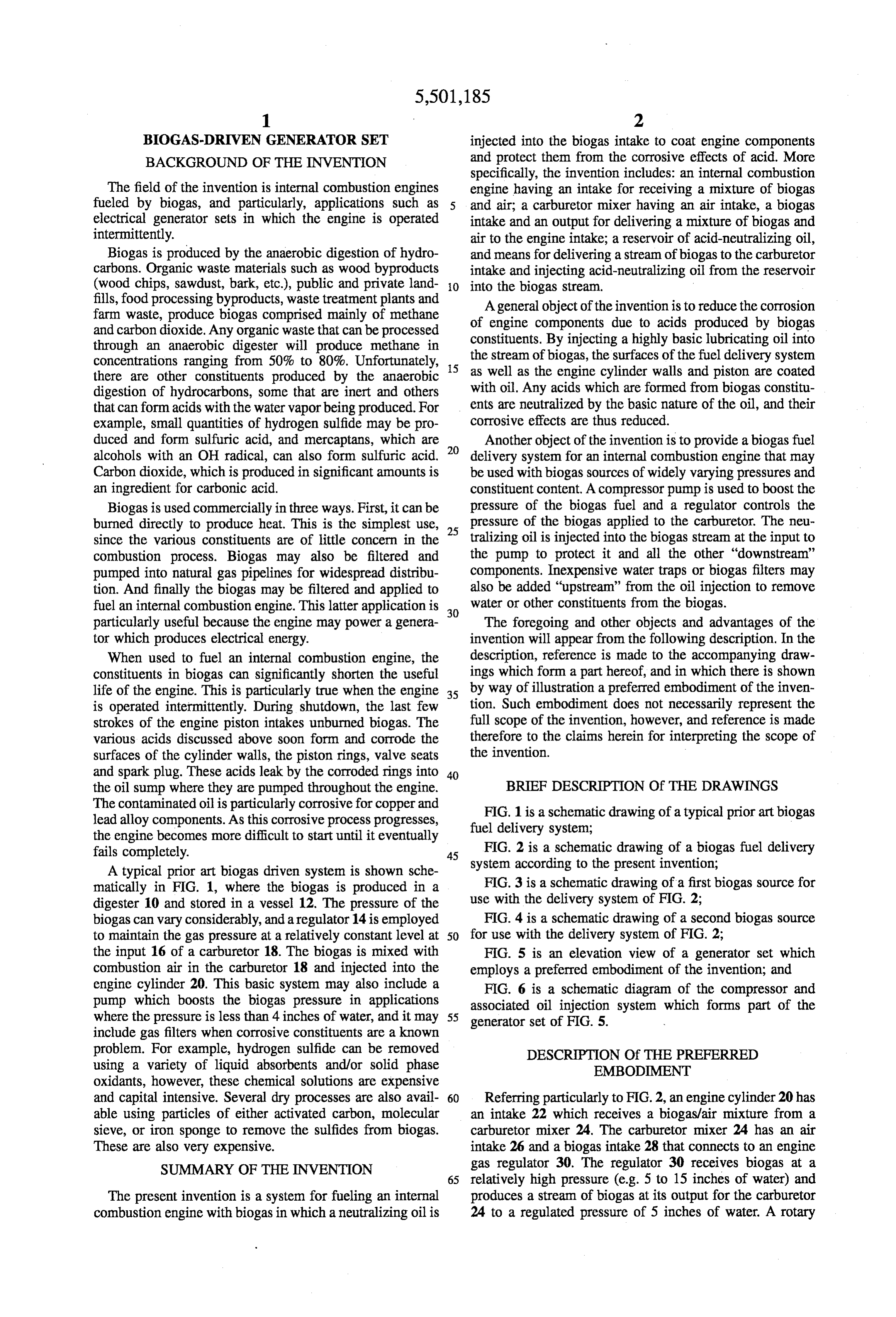
BIOGAS-DRIVEN GENERATOR SET injected into the biogas intake to coat engine components BACKGROUND OF THE INVENTION and protect them from the corrosive effects of acid. More specifically, the invention includes: an internal combustion
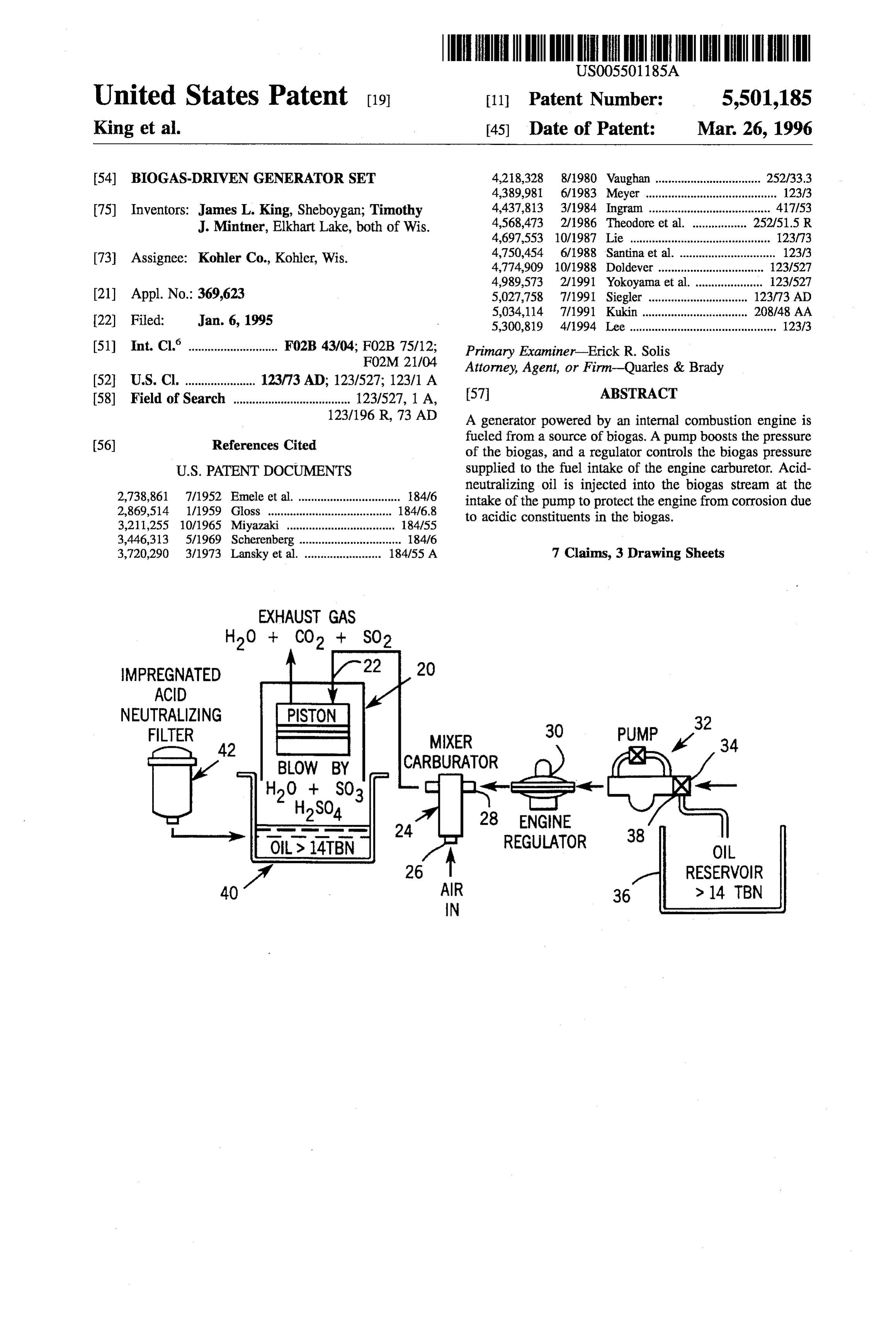
The field of the invention is internal combustion engines engine having an intake for receiving a mixture of biogas fueled by biogas, and particularly, applications such as and air; a carburetor mixer having an air intake, a biogas electrical generator sets in which the engine is operated intake and an output for delivering a mixture of biogas and intermittently. air to the engine intake; a reservoir of acid-neutralizing oil, Biogas is produced by the anaerobic digestion of hydro and means for delivering a stream of biogas to the carburetor carbons. Organic waste materials such as wood byproducts intake and injecting acid-neutralizing oil from the reservoir (wood chips, sawdust, bark, etc.), public and private land O into the biogas stream.
fills, food processing byproducts, waste treatment plants and farm waste, produce biogas comprised mainly of methane of Aengine general object of the invention is to reduce the corrosion and carbon dioxide. Any organic waste that can be processed constituents.components due to acids produced by biogas By injecting a highly basic lubricating oil into through an anaerobic digester will produce methane in concentrations ranging from 50% to 80%. Unfortunately, 5 the stream of biogas, the surfaces of the fuel delivery system there are other constituents produced by the anaerobic as well as the engine cylinder walls and piston are coated digestion of hydrocarbons, some that are inert and others with oil. Any acids which are formed from biogas constitu that can form acids with the water vapor being produced. For ents are neutralized by the basic nature of the oil, and their example, small quantities of hydrogen sulfide may be pro corrosive effects are thus reduced. duced and form sulfuric acid, and mercaptans, which are 20 Another object of the invention is to provide a biogas fuel alcohols with an OH radical, can also form sulfuric acid. delivery system for an internal combustion engine that may Carbon dioxide, which is produced in significant amounts is be used with biogas sources of widely varying pressures and an ingredient for carbonic acid. constituent content. A compressor pump is used to boost the Biogas is used commercially in three ways. First, it can be pressure of the biogas fuel and a regulator controls the burned directly to produce heat. This is the simplest use, 25 pressure of the biogas applied to the carburetor. The neu since the various constituents are of little concern in the tralizing oil is injected into the biogas stream at the input to combustion process. Biogas may also be filtered and the pump to protect it and all the other "downstream” pumped into natural gas pipelines for widespread distribu components. Inexpensive water traps or biogas filters may tion. And finally the biogas may be filtered and applied to also be added "upstream” from the oil injection to remove fuel an internal combustion engine. This latter application is 30 water or other constituents from the biogas. particularly useful because the engine may power a genera The foregoing and other objects and advantages of the tor which produces electrical energy. invention will appear from the following description. In the When used to fuel an internal combustion engine, the description, reference is made to the accompanying draw constituents in biogas can significantly shorten the useful ings which form a part hereof, and in which there is shown life of the engine. This is particularly true when the engine 35 by way of illustration a preferred embodiment of the inven is operated intermittently. During shutdown, the last few tion. Such embodiment does not necessarily represent the strokes of the engine piston intakes unburned biogas. The full scope of the invention, however, and reference is made various acids discussed above soon form and corrode the therefore to the claims herein for interpreting the scope of surfaces of the cylinder walls, the piston rings, valve seats the invention.
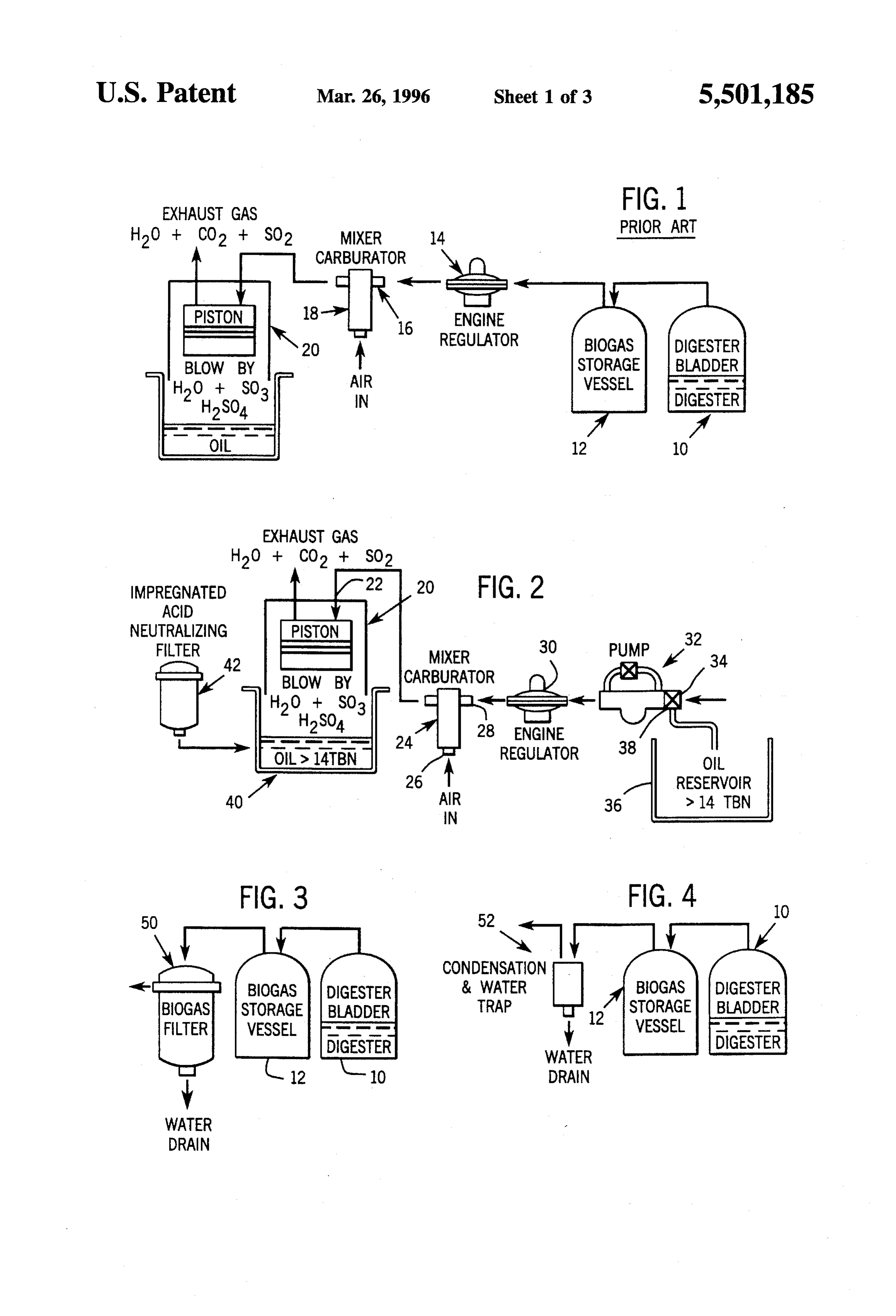
and spark plug. These acids leak by the corroded rings into 40 the oil sump where they are pumped throughout the engine. BRIEF DESCRIPTION Of THE DRAWINGS The contaminated oil is particularly corrosive for copper and FIG. 1 is a schematic drawing of a typical prior art biogas lead alloy components. As this corrosive process progresses, fuel delivery system;
the engine becomes more difficult to start until it eventually fails completely. 45
FIG. 2 is a schematic drawing of a biogas fuel delivery
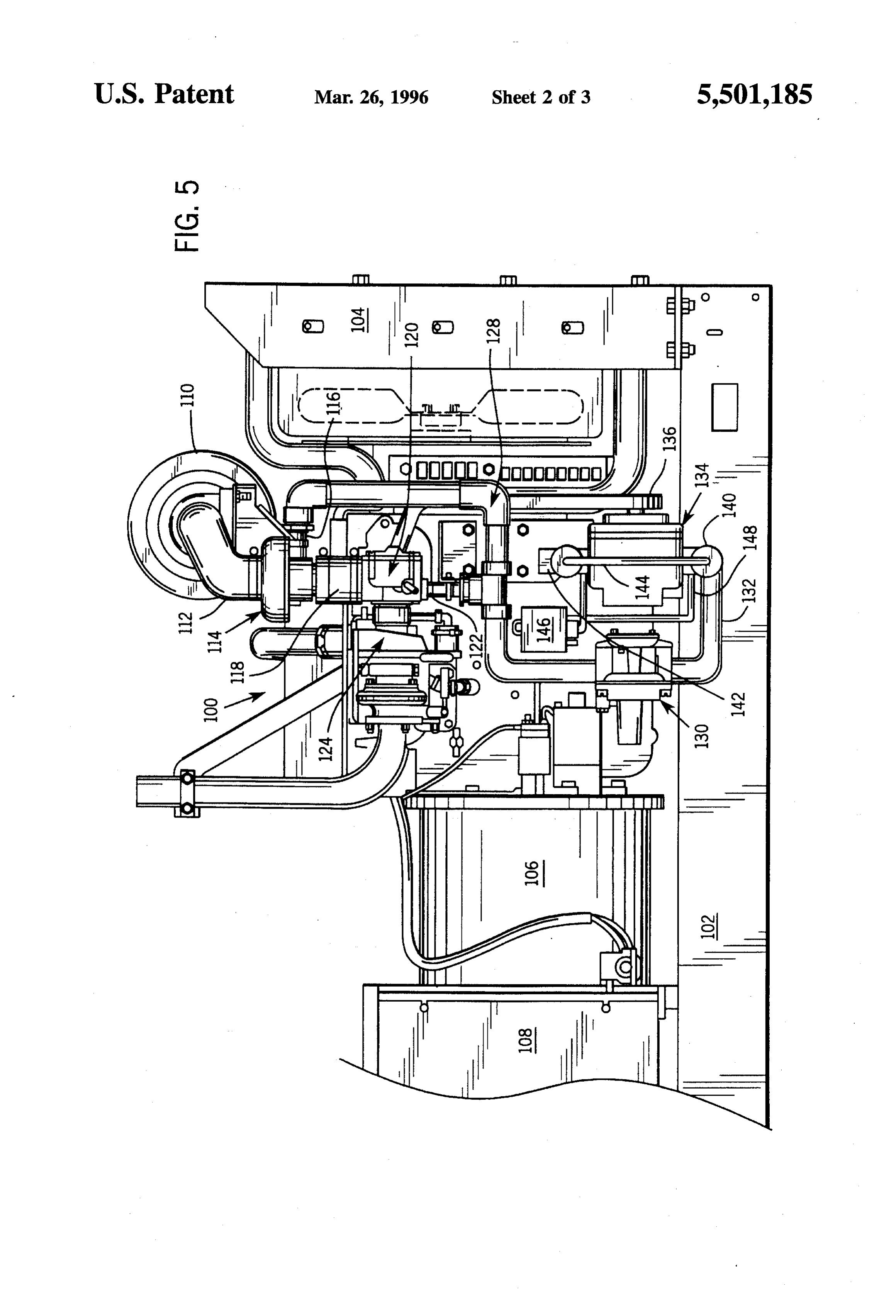
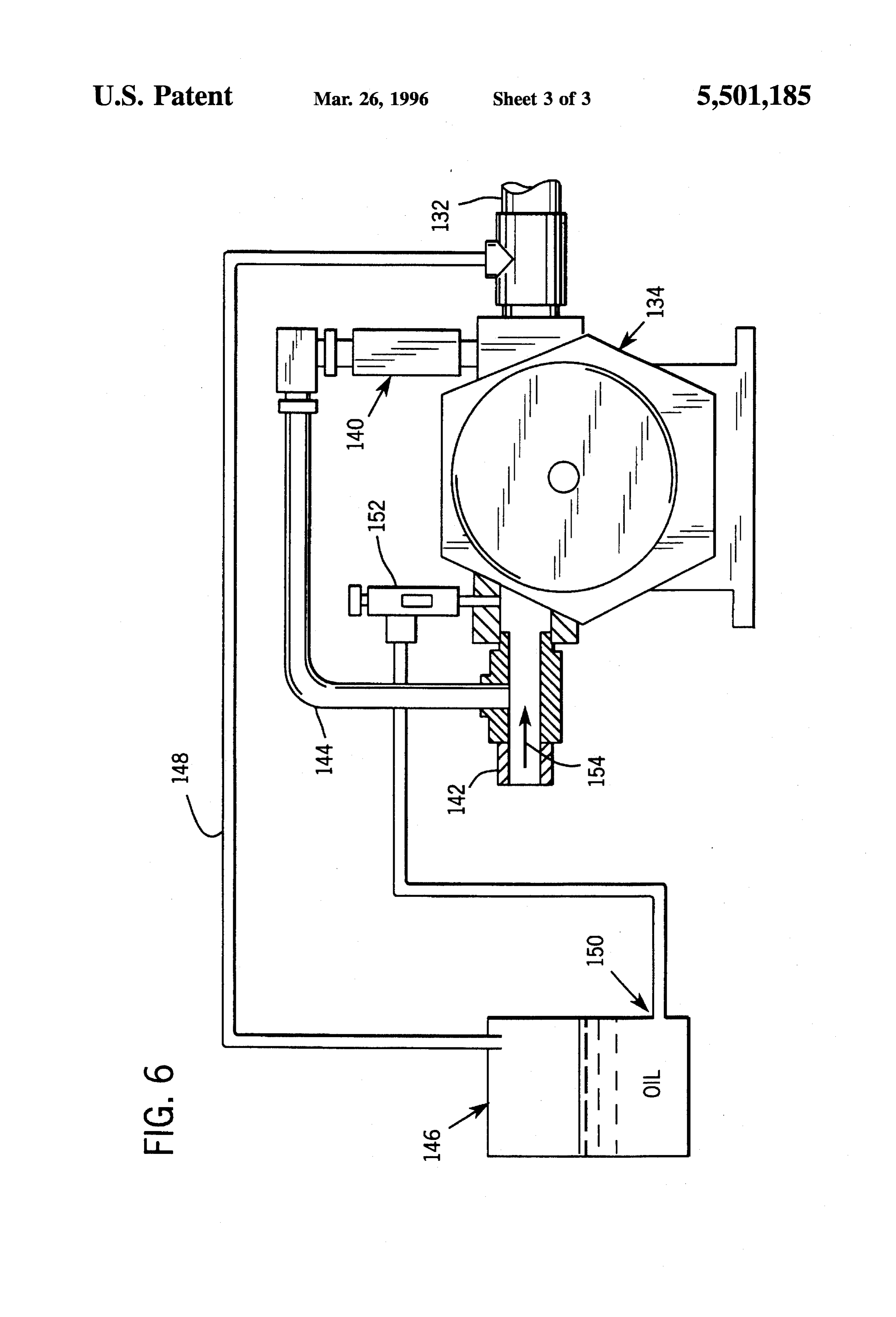
A typical prior art biogas driven system is shown sche system according to the present invention; matically in FIG. 1, where the biogas is produced in a FIG. 3 is a schematic drawing of a first biogas source for digester 10 and stored in a vessel 12. The pressure of the use with the delivery system of FIG. 2; biogas can vary considerably, and aregulator 14 is employed FIG. 4 is a schematic drawing of a second biogas source to maintain the gas pressure at a relatively constant level at 50 for use with the delivery system of FIG. 2; the input 16 of a carburetor 18. The biogas is mixed with FIG. 5 is an elevation view of a generator set which combustion air in the carburetor 18 and injected into the employs a preferred embodiment of the invention; and engine cylinder 20. This basic system may also include a FIG. 6 is a schematic diagram of the compressor and pump which boosts the biogas pressure in applications associated oil injection system which forms part of the where the pressure is less than 4 inches of water, and it may 55 generator set of FIG. 5.
include gas filters when corrosive constituents are a known problem. For example, hydrogen sulfide can be removed DESCRIPTION Of THE PREFERRED using a variety of liquid absorbents and/or solid phase EMBODIMENT oxidants, however, these chemical solutions are expensive and capital intensive. Several dry processes are also avail 60 Referring particularly to FIG.2, an engine cylinder 20 has able using particles of either activated carbon, molecular an intake 22 which receives a biogas/air mixture from a sieve, or iron sponge to remove the sulfides from biogas. carburetor mixer 24. The carburetor mixer 24 has an air These are also very expensive. intake 26 and a biogas intake 28 that connects to an engine SUMMARY OF THE INVENTION gas regulator 30. The regulator 30 receives biogas at a 65 relatively high pressure (e.g. 5 to 15 inches of water) and
The present invention is a system for fueling an internal produces a stream of biogas at its output for the carburetor combustion engine with biogas in which a neutralizing oil is 24 to a regulated pressure of 5 inches of water. A rotary
Page 6
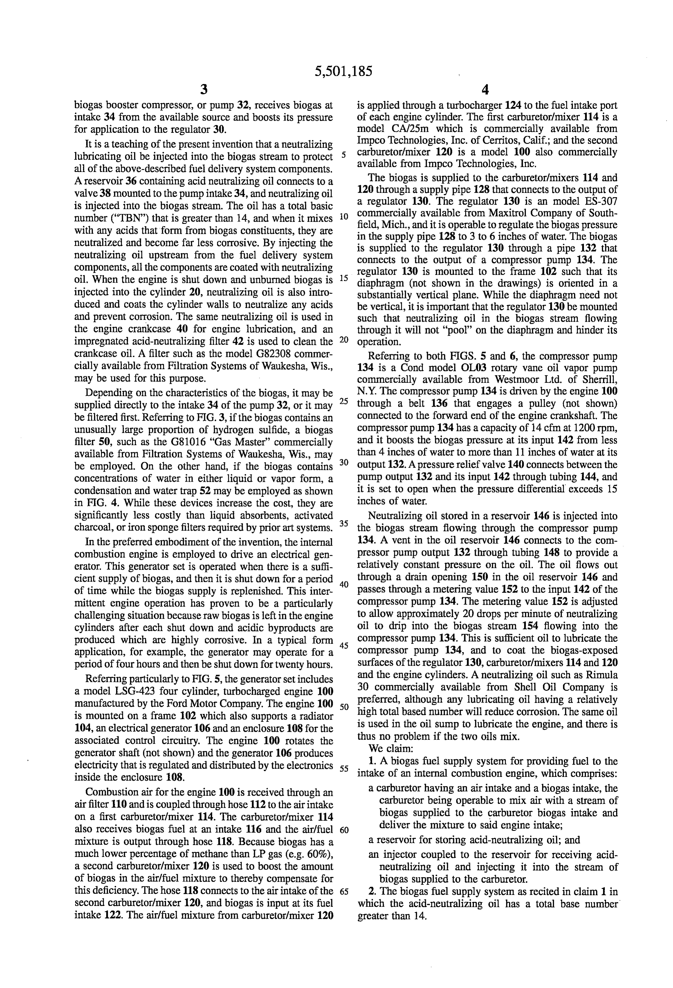
biogas booster compressor, or pump 32, receives biogas at is applied through a turbocharger 124 to the fuel intake port intake 34 from the available source and boosts its pressure of each engine cylinder. The first carburetor/mixer 114 is a for application to the regulator 30. model CA/25m which is commercially available from It is a teaching of the present invention that a neutralizing ImpcoTechnologies, Inc. of Cerritos, Calif.; and the second lubricating oil be injected into the biogas stream to protect 5 carburetor/mixer available from 120 is a model 100 also commercially
Impco Technologies, Inc.
all of the above-described fuel delivery system components.
A reservoir 36 containing acid neutralizing oil connects to a The biogas is supplied to the carburetor/mixers 114 and valve 38 mounted to the pumpintake 34, and neutralizing oil 120 through a supply pipe 128 that connects to the output of is injected into the biogas stream. The oil has a total basic a regulator 130. The regulator 130 is an model ES-307 number ("TBN') that is greater than 14, and when it mixes O commercially available from Maxitrol Company of South field, Mich., and it is operable to regulate the biogas pressure with any acids that form from biogas constituents, they are in the supply pipe 128 to 3 to 6 inches of water. The biogas neutralized and become far less corrosive. By injecting the is supplied to the regulator 130 through a pipe 132 that neutralizing oil upstream from the fuel delivery system connects to the output of a compressor pump 134. The components, all the components are coated with neutralizing regulator 130 is mounted to the frame 102 such that its oil. When the engine is shut down and unburned biogas is 15 diaphragm (not shown in the drawings) is oriented in a injected into the cylinder 20, neutralizing oil is also intro substantially vertical plane. While the diaphragm need not duced and coats the cylinder walls to neutralize any acids be vertical, it is important that the regulator 130 be mounted and prevent corrosion. The same neutralizing oil is used in such that neutralizing oil in the biogas stream flowing the engine crankcase 40 for engine lubrication, and an through it will not "pool” on the diaphragm and hinder its impregnated acid-neutralizing filter 42 is used to clean the 20 operation.
crankcase oil. A filter such as the model G82308 commer Referring to both FIGS. 5 and 6, the compressor pump cially available from Filtration Systems of Waukesha, Wis., 134 is a Cond model OL03 rotary vane oil vapor pump may be used for this purpose. commercially available from Westmoor Ltd. of Sherrill, Depending on the characteristics of the biogas, it may be 25 N.Y. The compressor pump 134 is driven by the engine 100 supplied directly to the intake 34 of the pump 32, or it may through a belt 136 that engages a pulley (not shown) be filtered first. Referring to FIG.3, if the biogas contains an connected to the forward end of the engine crankshaft. The unusually large proportion of hydrogen sulfide, a biogas compressor pump 134 has a capacity of 14 cfm at 1200 rpm, filter 50, such as the G81016 "Gas Master” commercially and it boosts the biogas pressure at its input 142 from less available from Filtration Systems of Waukesha, Wis., may 30 than 4 inches of water to more than 11 inches of water at its be employed. On the other hand, if the biogas contains output 132. A pressure relief valve 140 connects between the concentrations of water in either liquid or vapor form, a pump output 132 and its input 142 through tubing 44, and condensation and water trap 52 may be employed as shown it is set to open when the pressure differential exceeds 15 in FIG. 4. While these devices increase the cost, they are inches of water.
significantly less costly than liquid absorbents, activated 35 Neutralizing oil stored in a reservoir 146 is injected into charcoal, or iron sponge filters required by prior art systems. the biogas stream flowing through the compressor pump In the preferred embodiment of the invention, the internal 134. A vent in the oil reservoir 146 connects to the com combustion engine is employed to drive an electrical gen pressor pump output 132 through tubing 148 to provide a erator. This generator set is operated when there is a suffi relatively constant pressure on the oil. The oil flows out cient supply of biogas, and then it is shut down for a period 40 through a drain opening 150 in the oil reservoir 146 and of time while the biogas supply is replenished. This inter passes through a metering value 152 to the input 142 of the mittent engine operation has proven to be a particularly compressor pump 134. The metering value 152 is adjusted challenging situation because raw biogas is left in the engine to allow approximately 20 drops per minute of neutralizing cylinders after each shut down and acidic byproducts are oil to drip into the biogas stream 154 flowing into the produced which are highly corrosive. In a typical form 45 compressor pump 134. This is sufficient oil to lubricate the application, for example, the generator may operate for a compressor pump 134, and to coat the biogas-exposed period of four hours and then be shut down for twenty hours. surfaces of the regulator 130, carburetor/mixers 114 and 120 Referring particularly to FIG. 5, the generator set includes and the engine cylinders. A neutralizing oil such as Rimula a model LSG-423 four cylinder, turbocharged engine 100 preferred, 30 commercially available from Shell Oil Company is manufactured by the Ford Motor Company. The engine 100 50 although any lubricating oil having a relatively is mounted on a frame 102 which also supports a radiator is used in the oilnumber high total based will reduce corrosion. The same oil sump to lubricate the engine, and there is 104, an electrical generator 106 and an enclosure 108 for the associated control circuitry. The engine 100 rotates the thus no problem if the two oils mix. generator shaft (not shown) and the generator 106 produces We claim:
electricity that is regulated and distributed by the electronics 55 1. A biogas fuel supply system for providing fuel to the inside the enclosure 108. intake of an internal combustion engine, which comprises: Combustion air for the engine 100 is received through an a carburetor having an air intake and a biogas intake, the air filter 110 and is coupled through hose 112 to the air intake carburetor being operable to mix air with a stream of on a first carburetor/mixer 114. The carburetor/mixer 114 biogas supplied to the carburetor biogas intake and also receives biogas fuel at an intake 116 and the air/fuel 60 deliver the mixture to said engine intake; mixture is output through hose 118. Because biogas has a a reservoir for storing acid-neutralizing oil; and much lower percentage of methane than LP gas (e.g. 60%), an injector coupled to the reservoir for receiving acid a second carburetor/mixer 120 is used to boost the amount neutralizing oil and injecting it into the stream of of biogas in the air/fuel mixture to thereby compensate for biogas supplied to the carburetor. this deficiency. The hose 118 connects to the air intake of the 65 2. The biogas fuel supply system as recited in claim 1 in second carburetor/mixer 120, and biogas is input at its fuel which the acid-neutralizing oil has a total base number intake 122. The air/fuel mixture from carburetor/mixer 120 greater than 14.
Page 7
3. The biogas fuel supply system as recited in claim 1 in 6. The biogas fuel supply system as recited in claim 5 in which a regulator is connected to receive the oil injected which the reservoir is an enclosed container having a drain stream of biogas and supply said oil injected stream of connected to the injector valve and a vent connected for biogas to the carburetor at a substantially constant pressure. pressurization.
4. The biogas fuel supply system, as recited in claim3, in 7. The biogas fuel supply systems, as recited in claim 6, which a pump is connected to receive the oil-injected stream which includes a pump for boosting the pressure of the of biogas at its intake and to supply said oil-injected stream of biogas to the engine regulator at a substantially higher biogas stream supplied to the carburetor, and the injector is pressure than that at the pump intake. connected to the input of the pump, and the reservoir vent is 5. The biogas fuel supply system, as recited in claim 1, in 10 connected to the output of the pump. which the injector is a valve which controls the rate at which acid-neutralizing oil flows into the biogas stream. ck k is k
Provenance
- Collection
- Patents citing this work
- Original assignee
- Kohler Co
- Pages
- 7
- Method
- pdftotext (the PDF's own text layer) + pdftoppm 300dpi page scans
- Patent office record
- patents.google.com →
- Source
- Google Patents citing-documents table
- Inventors
- James L. King; Timothy J. Mintner; Kohler Co
- Published
- 1996-03-26
- Transcribed from
- patentimages.storage.googleapis.com →