patent · US3720290
Supersonic lubricator
13 March 1973
Page 1 — bibliographic record
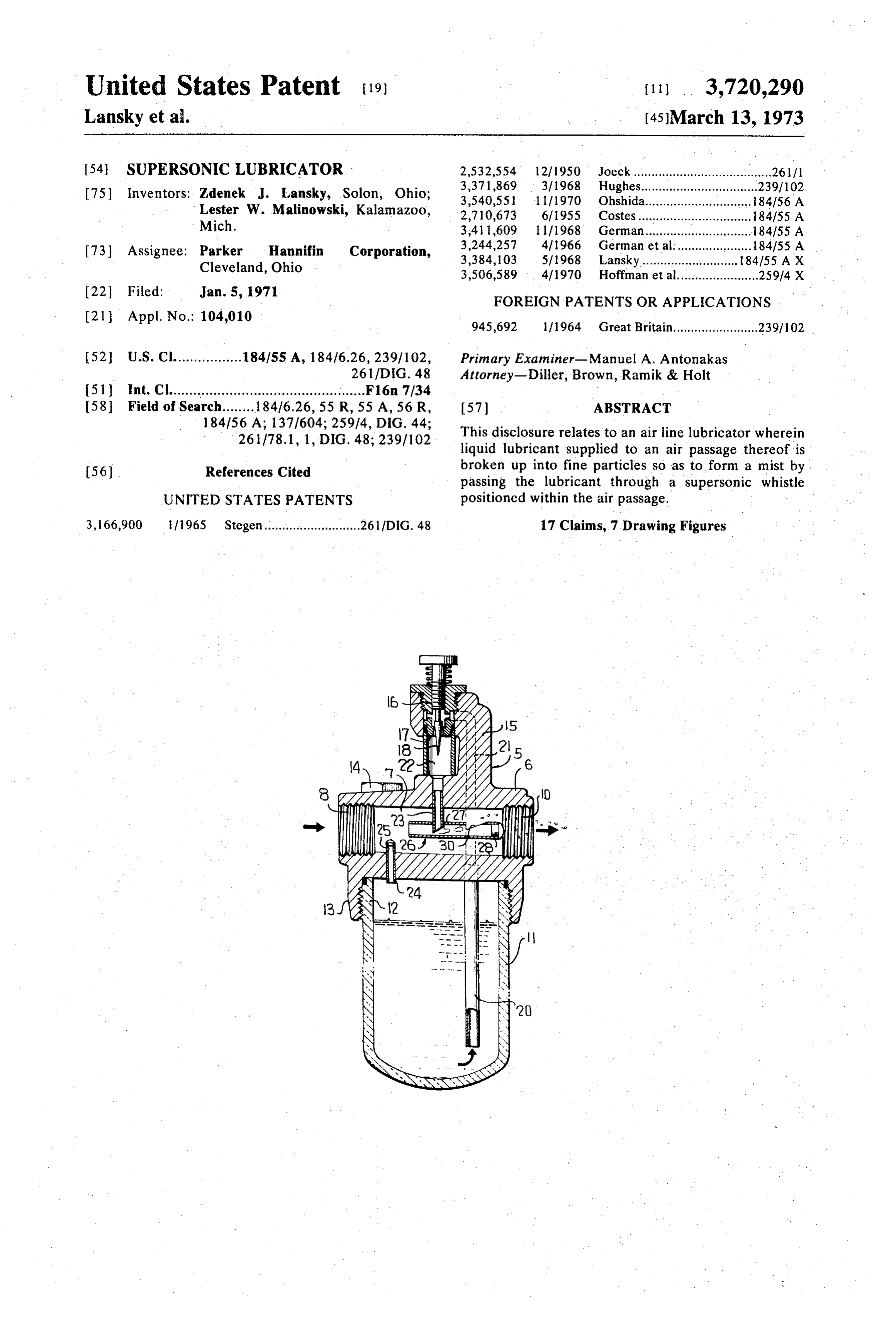
United States Patent (19) (11) 3,720,290 Lansky et al. (45 March 13, 1973 (54) SUPERSONICLUBRICATOR 2,532,554 12/1950 Joeck....... - 26111
75 Inventors: Zdenek J. Lansky, Solon, Ohio; 3,371,869 3/1968 Hughes................................. 2391 102 3,540,551 1 1/1970 Ohshida.... ... 184/56 A
Lester W. Malinowski, Kalamazoo, 2,710,673 6/1955 Costes............. ..., 184/55. A Mich. 3.41 1,609 1 1/1968 German........... ... 184155 A 73) Assignee: Parker Hannifin Corporation, 3,244,257 4/1966 German et al...................... 184155 A Cleveland, Ohio 3,384, 103 5/1968 Lansky................ ... 184155 A X 3,506,589 4/1970 Hoffman et al....................... 25914 X 22 Filed: Jan. 5, 1971 FOREIGN PATENTS OR APPLICATIONS (21) Appl. No.: 104,010 945,692 lf 1964. Great Britain........................ 239/102 52 U.S. Cl................. 184/55 A, 184/6.26, 23.9/102, Primary Examiner-Manuel A. Antonakas 261/DIG. 48 Attorney-Diller, Brown, Ramik & Holt 51 int. Cl................................................. F16n 7/34 58) Field of Search........ 184/6.26, 55 R, 55 A, 56 R, 57 ABSTRACT
261/78. 1, 1, DIG. 48; 23.9/102 This disclosure relates to an air line lubricator wherein liquid lubricant supplied to an air passage thereof is 56 References Cited broken up into fine particles so as to form a mist by passing the lubricant through a supersonic whistle
UNITED STATES PATENTS positioned within the air passage.
3, 66,900 1965 Stegen........................... 26 l/DIG. 48 17 Claims, 7 Drawing Figures
Page 2
Drawing sheet — no readable text.
Page 3
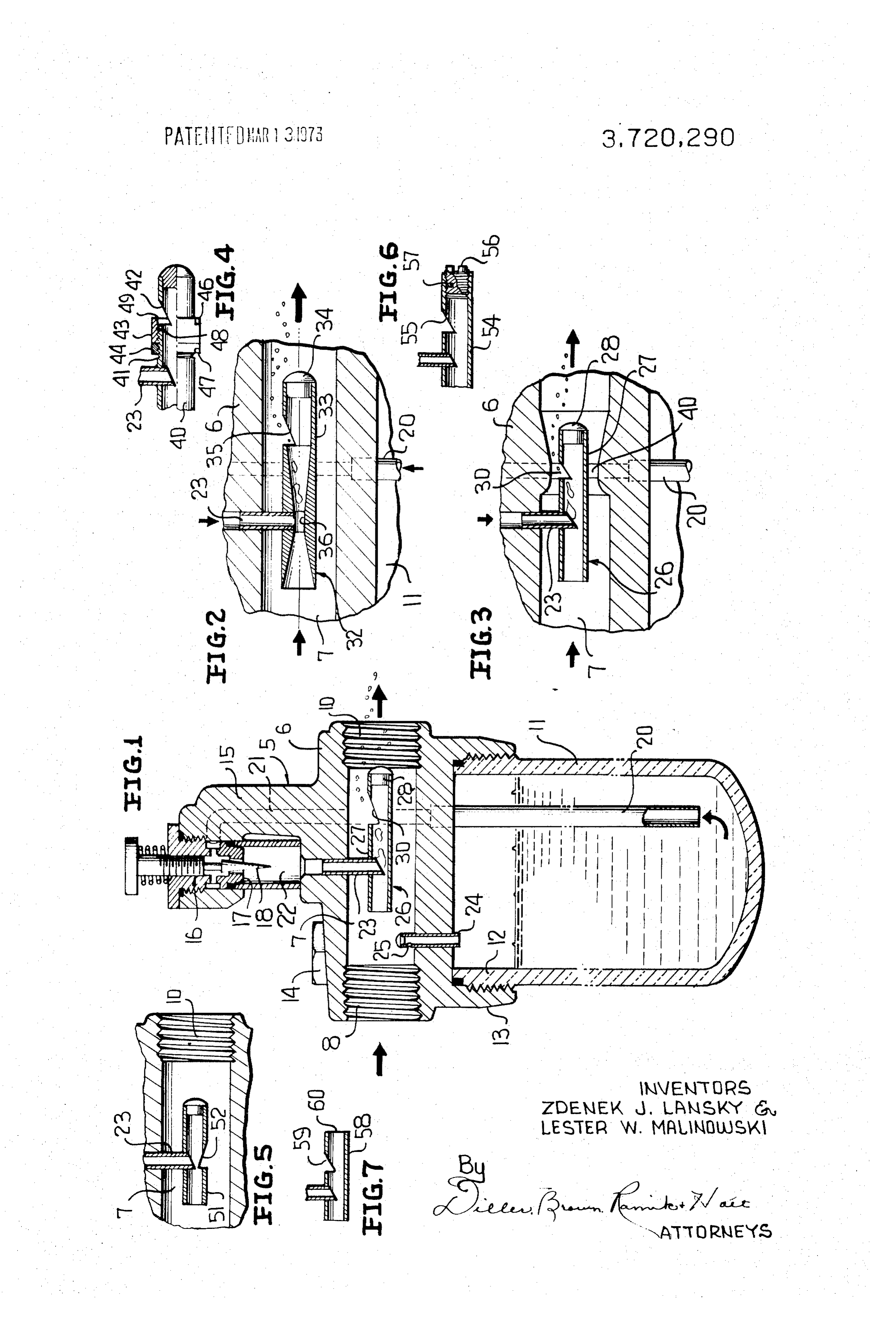
SUPERSONICLUBRICATOR generator in which the air passage around the whistle This invention relates in general to new and useful tube has a venturi section.
improvements in air line lubricators, and more particu FIG. 4 is a fragmentary view showing a means for larly to novel apparatus for supplying lubricant to air in varying the size of the side opening in the whistle tube. the form of a mist. FIG. 5 is a fragmentary view showing a modified BACKGROUND OF THE INVENTION form in which the lubricant feed tube is opposite the side opening in the whistle tube.
Conventional air line lubricators include an air FIG. 6 is a fragmentary cross section view showing a passage, a supply of liquid lubricant, and means for in O means for varying the frequency of the sound waves. troducing the lubricant into the air passage in a manner FIG. 7 is a view of a further modified whistle tube to cause the liquid lubricant to be broken up into fine that is open on both ends.
particle or mist form and be dispersed throughout the In the drawing, airline lubricator 5 includes a hous air passing through the passage. It is desirable that the ing 6 having an air passage 7 therethrough. The air particle size be very small, that a thorough mixing with 15 passage 7 includes an inlet 8 and outlet 10 to which the air be accomplished and that pressure drop of air suitable air lines may be connected.
passing through the lubricator be kept to a minimum. Lubricator 5 is also provided with a lubricant source SUMMARY in the form of a bowl 11 having an upper portion 12 which is threadably engaged with a sleeve portion 13 of
In accordance with this invention, a mist generator in housing 6.
the form of a supersonic whistle is mounted within the Housing 6 has a filling passage (not shown) closed by air passage of an air line lubricator, the mist generator a filler cap 14 wherein filling of bowl 11 may be accom receiving lubricant droplets and converting them into plished without removing same.
mist, which mist is then distributed into the air passing 25 Housing 6 has an upper extension 15 in which a me through the air passage. tering valve 16 is mounted. The metering valve 16 in The whistle is mounted within the air passage and as cludes valve element 17 and an adjustable meter valve the air passes through the whistle opening it undergoes 18.
turbulent flow that creates sound waves that shred the A pick-up tube 20 extends down into bowl 11 and is lubricant droplets to break them into fine particles and 30 in communication with a lubricant passage 21 which thoroughly mixes the particles with the air passing opens into the metering valve 16. Metered lubricant through the whistle. The particle size is a function of passes from metering valve 16 into a sight glass 22 and the sonic frequency and may be varied by varying the then into a lubricant tube 23 projecting into air passage frequency of the latter. 7.
The whistle may be of various suitable constructions. 35 Lubricant within bowl 11 is forced up through pick in one form it comprises a tube of uniform diameter, up tube 20 and to metering valve 16 by air pressure closed at one end and having a side opening therein ad within bowl 11. This air pressure is supplied by a pres jacent the closed end. A lubricant tube extends into the sure tap 24 extending from air passage 7 down into whistle tube between the open end thereof and the side bowl 11. Pressure tap 24 has an entrance opening 25 opening and is shaped and positioned so as to create a 40 which faces upstream to transmit velocity pressure of pressure drop in the air passing through the whistle the air in passage 7 to the bowl so that the pressure in tube whereby lubricant is drawn into the whistle tube. the bowl is somewhat greater than the pressure in air In another form of the invention, the whistle tube has a venturi section into which the lubricant tube opens 8passage 7. In a typical installation, air is applied at inlet whereby the lowered pressure in the venturi section 45 let 10 is 75 psiofand at the rate 125 cfm and 80 psi. Air pressure at out air pressure within bowl 11 is 82 psi.
causes lubricant to be drawn into the whistle tube.
In order that lubricant
In still other forms of the invention a means may be may be atomized and delivered supplied through lubricant 23 provided for varying the position of the side opening into the air passing through air passage 7 in the relative to the end of the tube whereby the sonic vided a mist generator 26. Mist generator form of a mist, there is pro frequency, and hence the lubricant particle size, may SO form 26 is in the be adjusted or varied. of a simple supersonic whistle including a tube 27 With the above and other objects in view that will of uniform inside diameter having its downstream end hereinafter appear, the nature of the invention will be closed by a plug 28 and being provided with a generally more clearly understood by reference to the following triangular side opening 30 adjacent the plugged end. detailed description, the appended claimed subject 55 Whistle tube 27 is supported on lubricant tube 23 by matter, and the several views illustrated in the accom a press fit between the two where the lubricant tube ex panying drawing. tends into the whistle tube between the open end of the whistle tube and side opening 30. The lower end of
DESCRIPTION OF THE INVENTION lubricant tube 23 is cut at an angle and faces generally FIG. 1 is a vertical sectional view taken through an 60 downstream so as to lower the pressure of air in the air line lubricator utilizing a whistle tube of uniform in whistle tube adjacent the lower end of lubricant tube side diameter as a mist generator. 23 to further increase the differential in pressure FIG. 2 is an enlarged fragmentary sectional view between the pressure in the whistle tube and that in showing a whistle type mist generator in which the 65 bowl 11 whereby such differential causes lubricant to whistle tube includes a venturi section. pass from bowl 11 through pickup tube 20, passage 21, FIG. 3 is an enlarged fragmentary sectional view chamber 22 and tube 23 into whistle 26 where it is car similar to FIG. 2 and shows still another form of mist ried to opening 30.
Page 4
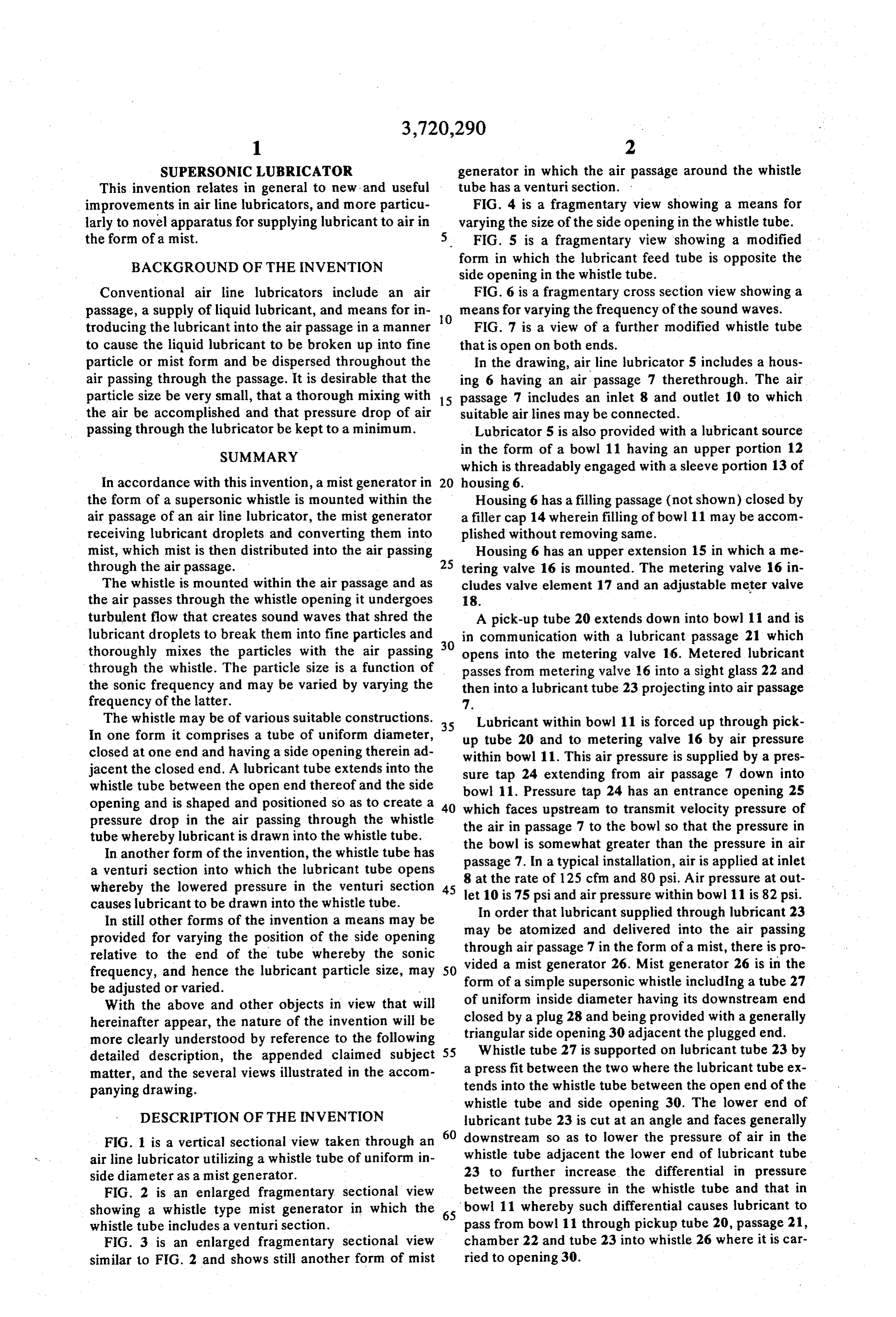
Air passing out through opening 30 becomes turbu Preferably the sound waves are in the supersonic lant and creates supersonic waves that tear the lubri range of 15,000 cycles per second or more but in some cant droplets into very fine particles which become applications may be as low as 10,000 cycles per second. thoroughly mixed with the air passing through the side A preferred frequency is 20,000 cycles per second. opening. We claim:
In FIG. 2 there is illustrated a modified form of whis 1. An airline lubricator comprising a housing having tle type mist generator 32 which includes a tube 33 an air passage therethrough and a source of lubricant, having a plug 34 closing the downstream end thereof onlymeans within said air passage for receiving a portion and being provided with a generally triangular side 10 of air passing through said air passage and creating opening 35 adjacent the plugged end. sound waves, and passage means for delivering lubri Generator 32 is supported by lubricant tube 23, but cant from said source across said air passage and to said in lieu of tube 23 passing into tube 33, tube 33 is pro sound creating means for dividing the lubricant into vided with a venturi section 36 between the tube inlet small particles by the sound waves and delivering the and opening 35. Lubricant tube 23 opens into venturi 15 small particles to the downstream side of the air section 36. Lubricant is drawn into whistle tube 33 due passage.
to pressure drop in venturi section 36. 2. The lubricator of claim 1 in which said means for In the modification of FIG. 3, whistle tube 26 is the creating sound waves is in the form of a whistle tube same as that in FIG. 1 but air passage 7 is provided with having an opening in its side. a venturi section 40 opposite side opening 30. This 20 3. The lubricator of claim 2 in which said passage causes an increase in the velocity of the air in passage 7 means cludes for delivering lubricant to the whistle tube in a conduit communicating with the interior of the as it passes over opening 30 as well as a decrease in the whistle tube pressure thereof and further assists atomization and end of the tubebetween upstream said side opening and an open of the side opening.
mixing of the oil with the air. The venturi 40 may 25 4. The lubricator of claim 1 in which the sound waves likewise be used in conjunction with the venturi type have a frequency of over 10,000 cycles per second. whistle generator 32 of FIG. 2. 5. The lubricator of claim 3 in which said whistle In the modification of FIG. 4 a cylindrical whistle tube includes a venturi section and said conduit pro tube 40 has a thread 41 formed between lubricant tube jects into 23 and side opening 42 and a sleeve 43 and a locknut 30 ing end facing the interior of the whistle tube and has a slop 44 are threaded thereon. The sleeve 43 and locknut 44 toward said side opening. 6. The lubricator of claim 3 in which said whistle may have notches 46, 47 therein for receiving a tool for tube is suspended in said air passage by said conduit. turning the same. Whistle tube 40 has a smooth diame 7. The lubricator of claim 2 in which said air passage ter portion 48 between thread 41 and notch 42 that has includes a venturi section and said whistle tube is posi a close sliding fit with a smooth cylindrical portion 49 35 tioned in said air passage with said side opening within of sleeve 43. Threading sleeve 43 in one direction or the venturi section.
the other on thread 41 increases or decreases the size 8. The lubricator of claim 2 in which there is a means and shape of side opening 42 which adjusts and con for varying the size of the side opening. trols the variation in the size of the particles of lubri 9. The lubricator of claim 2 in which the whistle tube cant and which to some extent also varies the particle 40 has an open end facing the upstream side of the air size by varying the pitch or frequency of the sound passage and a closed end and said side opening is WaWes. between said ends.
In the modification of FIG. 5 whistle tube 51 is 10. The lubricator of claim 9 in which there is a turned upside down from the position shown in FIG. 1 45 means for varying the distance between the side open and lubricant tube 23 enters the whistle tube radially ing and said closed end.
opposite side opening 52, therefore delivering the oil 11. The lubricator of claim 2 in which there is a directly into the zone of turbulent air within the whistle means for varying the position of the side opening tube. along the length of the tube.
F.G. 6 shows a whistle tube 54 in which the 50 12. The lubricator of claim 1 in which there is a downstream end of the same is closed by a plug 56 means for varying the frequency of said sound waves. threaded thereinto. The plug may be adjusted inwardly 13. An airline lubricator comprising a housing having or outwardly by the threaded connection to vary the a passage for air under pressure and having a reservoir distance between the side opening 55 and the closed containing lubricant, a tube in said air passage extend end of the tube 54 to thereby vary the frequency of the 55 ing axially therealong and having a first opening therein sound waves generated and hence the particle size of facing upstream of the air passage to receive air the lubricant. The plug is locked in its set position by an therefrom and having a second opening downstream of elastomeric insert 57 that frictionally engages the inter the first opening and communicating with the air nal thread of the tube. passage, means for creating sound waves in the tube In another form as shown in FIG. 7 the whistle tube 60 when air passes from the first opening to the second, 58 may be open on both ends, in which case the tube means connecting the upstream end of the air passage must be shorter between the side opening 59 and the to the reservoir to create a pressure upon the lubricant downstream end 60 than a tube with a closed end in therein, a conduit connecting the reservoir to the in order to produce the same frequency of sound wave. 65 terior of the tube, means creating a lower pressure at
In other forms of the invention the sound wave the connection of the conduit to the tube than in said producing means may be a reed or other device rather reservoir whereby lubricant flows to the tube and is di than a whistle tube. vided into small particle size by said sound waves, said
Page 5
particles being carried by the air passing from said first ing. opening to the second opening and delivered to the 16. The lubricator of claim 13 in which said sound downstream side of the air passage. waves have a frequency of more than 15,000 cycles per 14. The lubricator of claim 13 in which there is a second. means for varying the frequency of the sound waves. 5 17. The lubricator of claim 13 in which said tube is 15. The lubricator of claim 13 in which the second opening is in the side of the tube the connection of the open on both ends. conduit to the tube is radially opposite said side open
Provenance
- Collection
- Cited prior art
- Original PDF
- patentimages.storage.googleapis.com →
- Filed
- 1971-01-05
- Pages
- 5
- Method
- pdftotext (the PDF's own text layer) + pdftoppm 300dpi page scans
- Source
- Google Patents bibliographic record
- Granted
- 1973-03-13
- Inventors
- Z Lansky; L Malinowski; Parker Hannifin Corp
- Transcribed from
- patentimages.storage.googleapis.com →