patent · US4774909
Internal mixture formation
4 October 1988
Page 1 — bibliographic record
United States Patent (19) 11 Patent Number: 4,774,909 Dolderer (45) Date of Patent: Oct. 4, 1988 (54 INTERNAL MIXTURE FORMATION (56) References Cited
76 Inventor: Erich A. Dolderer, 14 Goethestrasse, 2,767,691 10/1956 Mengelkamp et al. ............ 123/1 A D-7406 Mossingen 1, Fed. Rep. of 2,872,911 2/1959 Botto ................... ... 23/527 Germany 4,503,832 3/1985 Pefley et al......................... 123/527
FOREIGN PATENT DOCUMENTS
(21) Appl. No.: 930,724 81/00282 2/1981 PCT Int'l Appl. ................. 123/527 Primary Examiner-E. Rollins Cross 22 Filed: Nov. 13, 1986 Attorney, Agent, or Firm-Porter, Wright, Morris & Arthur 30 Foreign Application Priority Data 57 ABSTRACT Nov. 15, 1985 (DE Fed. Rep. of Germany ....... 354484 A fuel injection system for an internal combustion en gine in which fuel density is adapted to ambient temper ature by a combination means heated by the engine 51) Int. Cl." .............................................. F02B 75/12 cooling system and the injection of fuel in to the engine 52 U.S.C. ..................................... 123/1A; 123/527 is related to pressure in the compensation means.
123/DIG. 12,472 35 Claims, 4 Drawing Sheets
Page 2
Drawing sheet — no readable text.
Page 3
Drawing sheet — no readable text.
Page 4
Drawing sheet — no readable text.
Page 5
Drawing sheet — no readable text.
Page 6
injection pump or between the needle of the nozzle and
INTERNAL MXTURE FORMATION its guide tube; this would require new methods of fabri cation. In addition, the lubrication problem is solved.
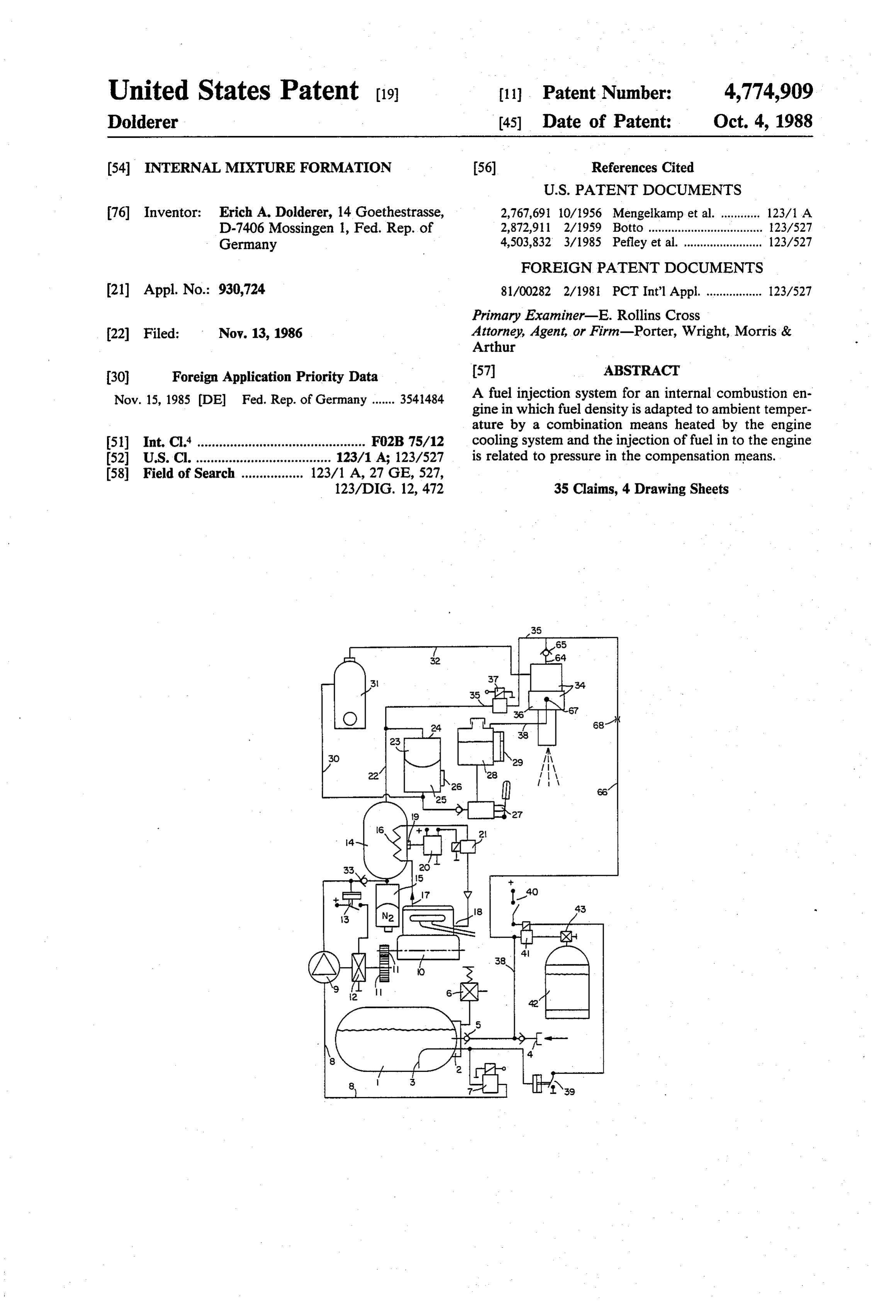
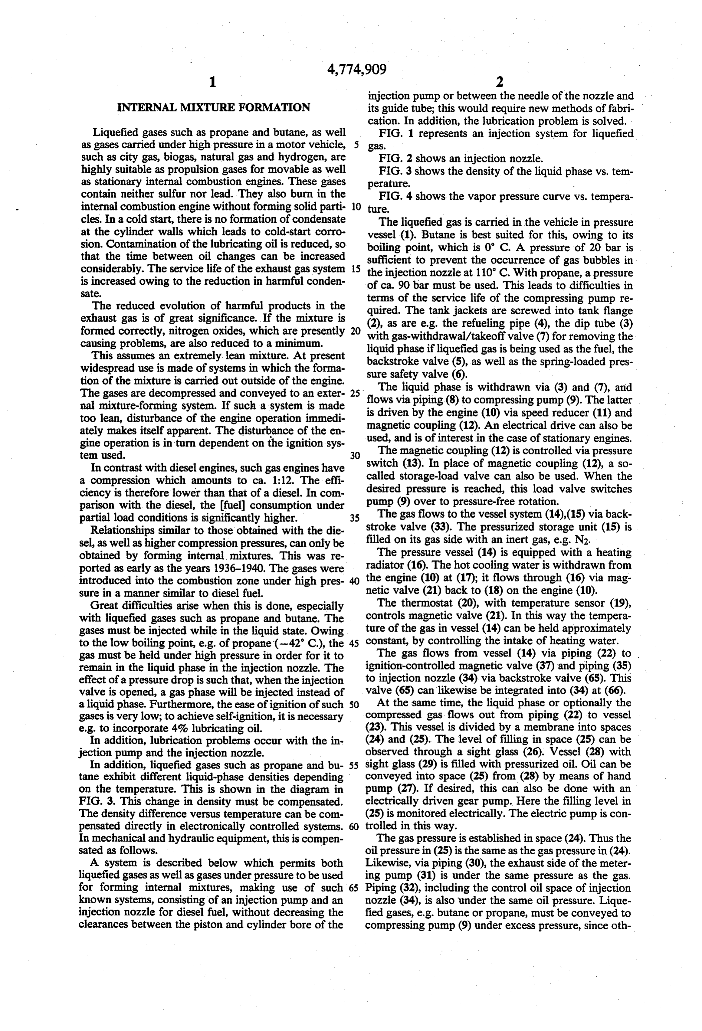
Liquefied gases such as propane and butane, as well FIG. 1 represents an injection system for liquefied as gases carried under high pressure in a motor vehicle, 5 gas.
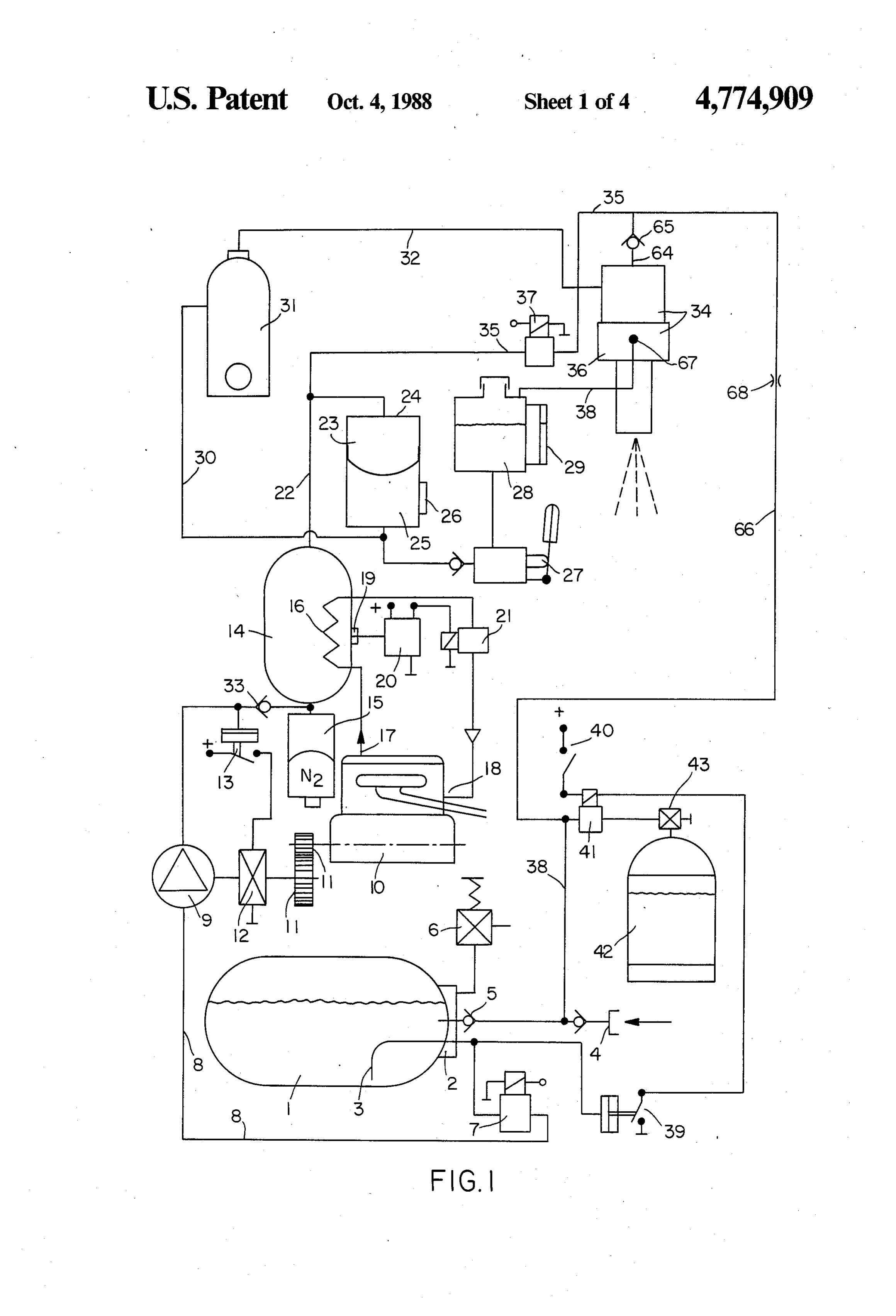
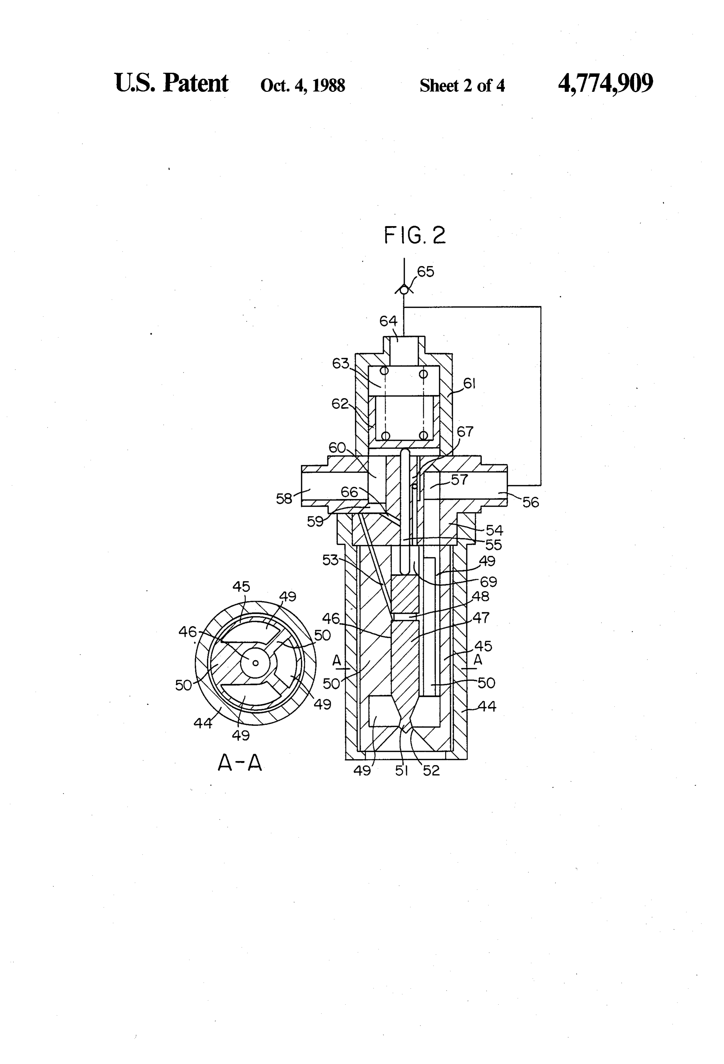
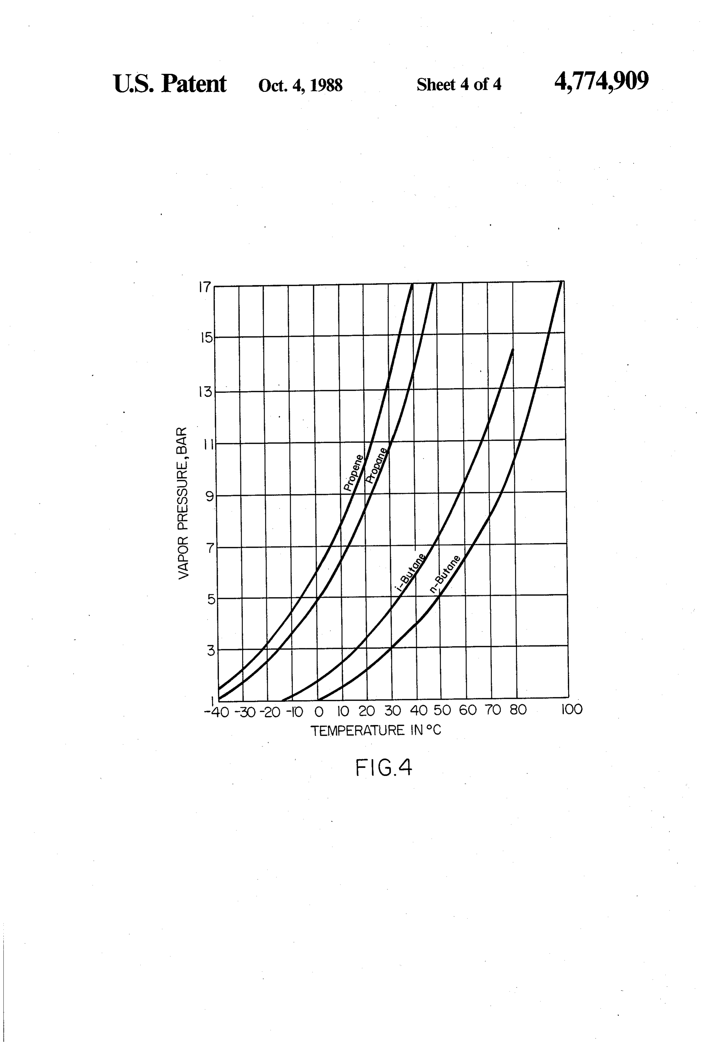
such as city gas, biogas, natural gas and hydrogen, are FIG. 2 shows an injection nozzle. highly suitable as propulsion gases for movable as well FIG. 3 shows the density of the liquid phase vs. tem as stationary internal combustion engines. These gases perature.
contain neither sulfur nor lead. They also burn in the FIG. 4 shows the vapor pressure curve vs. tempera internal combustion engine without forming solid parti O ture.
cles. In a cold start, there is no formation of condensate The liquefied gas is carried in the vehicle in pressure at the cylinder walls which leads to cold-start corro vessel (1). Butane is best suited for this, owing to its sion. Contamination of the lubricating oil is reduced, so boiling point, which is 0° C. A pressure of 20 bar is that the time between oil changes can be increased sufficient to prevent the occurrence of gas bubbles in considerably. The service life of the exhaust gas system 15 the injection nozzle at 110° C. With propane, a pressure is increased owing to the reduction in harmful conden of ca. 90 bar must be used. This leads to difficulties in Sate.
The reduced evolution of harmful products in the terms quired.
of the service life of the compressing pump re
The tank jackets are screwed into tank flange exhaust gas is of great significance. If the mixture is (2), as are e.g. the refueling pipe (4), the dip tube (3) formed correctly, nitrogen oxides, which are presently 20 with gas-withdrawal/takeoff valve (7) for removing the causing problems, are also reduced to a minimum. liquid phase if liquefied gas is being used as the fuel, the This assumes an extremely lean mixture. At present backstroke valve (5), as well as the spring-loaded pres widespread use is made of systems in which the forma sure safety valve (6).
tion of the mixture is carried out outside of the engine. The liquid phase is withdrawn via (3) and (7), and The gases are decompressed and conveyed to an exter 25 flows via piping (8) to compressing pump (9). The latter nal mixture-forming system. If such a system is made is driven too lean, disturbance of the engine operation immedi magnetic by the engine (10) via speed reducer (11) and coupling (12). An electrical drive can also be ately makes itself apparent. The disturbance of the en gine operation is in turn dependent on the ignition sys used, and is of interest in the case of stationary engines. ten used. 30 The magnetic coupling (12) is controlled via pressure In contrast with diesel engines, such gas engines have switch (13). In place of magnetic coupling (12), a so a compression which amounts to ca. 1:12. The effi called storage-load valve can also be used. When the ciency is therefore lower than that of a diesel. In com desired pressure is reached, this load valve switches parison with the diesel, the fuel) consumption under pump (9) over to pressure-free rotation. partial load conditions is significantly higher. 35 The gas flows to the vessel system (14),(15) via back Relationships similar to those obtained with the die stroke valve (33). The pressurized storage unit (15) is sel, as well as higher compression pressures, can only be filled on its gas side with an inert gas, e.g. N2. obtained by forming internal mixtures. This was re The pressure vessel (14) is equipped with a heating ported as early as the years 1936-1940. The gases were radiator (16). The hot cooling water is withdrawn from introduced into the combustion zone under high pres the engine (10) at (17); it flows through (16) via mag sure in a manner similar to diesel fuel. netic valve (21) back to (18) on the engine (10). Great difficulties arise when this is done, especially The thermostat (20), with temperature sensor (19), with liquefied gases such as propane and butane. The controls magnetic valve (21). In this way the tempera gases must be injected while in the liquid state. Owing ture of the gas in vessel (14) can be held approximately to the low boiling point, e.g. of propane (-42 C.), the 45 constant, by controlling the intake of heating water. gas must be held under high pressure in order for it to The gas flows from vessel (14) via piping (22) to remain in the liquid phase in the injection nozzle. The ignition-controlled magnetic valve (37) and piping (35) effect of a pressure drop is such that, when the injection to injection nozzle (34) via backstroke valve (65). This valve is opened, a gas phase will be injected instead of valve (65) can likewise be integrated into (34) at (66). a liquid phase. Furthermore, the ease of ignition of such SO At the same time, the liquid phase or optionally the gases is very low; to achieve self-ignition, it is necessary compressed gas flows out from piping (22) to vessel e.g. to incorporate 4% lubricating oil. (23). This vessel is divided by a membrane into spaces In addition, lubrication problems occur with the in (24) and (25). The level of filling in space (25) can be jection pump and the injection nozzle. observed through a sight glass (26). Vessel (28) with In addition, liquefied gases such as propane and bu 55 sight glass (29) is filled with pressurized oil. Oil can be tane exhibit different liquid-phase densities depending conveyed into space (25) from (28) by means of hand on the temperature. This is shown in the diagram in pump (27). If desired, this can also be done with an FIG. 3. This change in density must be compensated. electrically driven gear pump. Here the filling level in The density difference versus temperature can be com (25) is monitored electrically. The electric pump is con pensated directly in electronically controlled systems. trolled in this way.
In mechanical and hydraulic equipment, this is compen The gas pressure is established in space (24). Thus the sated as follows. oil pressure in (25) is the same as the gas pressure in (24). A system is described below which permits both Likewise, via piping (30), the exhaust side of the meter liquefied gases as well as gases under pressure to be used ing pump (31) is under the same pressure as the gas. for forming internal mixtures, making use of such 65 Piping (32), including the control oil space of injection known systems, consisting of an injection pump and an nozzle (34), is also under the same oil pressure. Lique injection nozzle for diesel fuel, without decreasing the fied gases, e.g. butane or propane, must be conveyed to clearances between the piston and cylinder bore of the compressing pump (9) under excess pressure, since oth
Page 7
erwise bubbles of vapor will form in line (8) which runs At the start of delivery by pump (31), the pressure from pressure vessel (1) to pump (9). rises under the piston until the force of pressure spring At temperatures below --3 C., the pressure in vessel (63) is reached. With further delivery, piston (63) moves (1) is no longer sufficient. This can cause difficulties in upward; as a result, the gas above the piston is brought starting. In order to circumvent these difficulties, the to a higher pressure, and in turn the pressure in spaces pressure in vessel (1) is monitored by means of pressure (49) also is increased. This pressure causes nozzle needle switch (39). If the pressure in vessel (1) falls below the (47) to follow the motion of pin (55) upward, which set point, magnetic valve (41) is actuated. However, this exposes borehole (52). The gas flows into the combus assumes that switch (40) is closed. It is coupled with the tion space of the cylinder of the internal combustion ignition switch, and is closed only if the ignition is 10 engine and is there ignited by the spark plug. turned on. In this way, propane gas (boiling point -42 When the oil pressure falls, pressure spring (63) acts C.) continues to flow out of vessel (42) via manual shut as a closure spring (51), shutting off the escape of gas at off valve (43) into pressure vessel (1), until pressure (52).
switch (39) opens and magnetic valve (41) closes. Dur There is constantly oil between parts (47) in borehole ing engine operation, a small amount of warmed butane 15 (46) and the borehole of pressure pin (55); it acts as a constantly flows through piping (67) with throttle (68) sealing fluid and a lubricant.
into pressure vessel (1), as a result of which a slight Only during the actual injection process is the oil excess pressure always prevails in this vessel. pressure somewhat higher than the gas pressure. Thus a This manner of generating pressure can be dispensed pressure balance practically always prevails. with in countries whose lowest temperature is +5 C. 20 The piston can also be controlled with a pressurized Figure 2 oil system, by means of a rapid-switching magnetic valve. In such a case, the metering of fuel is effected via
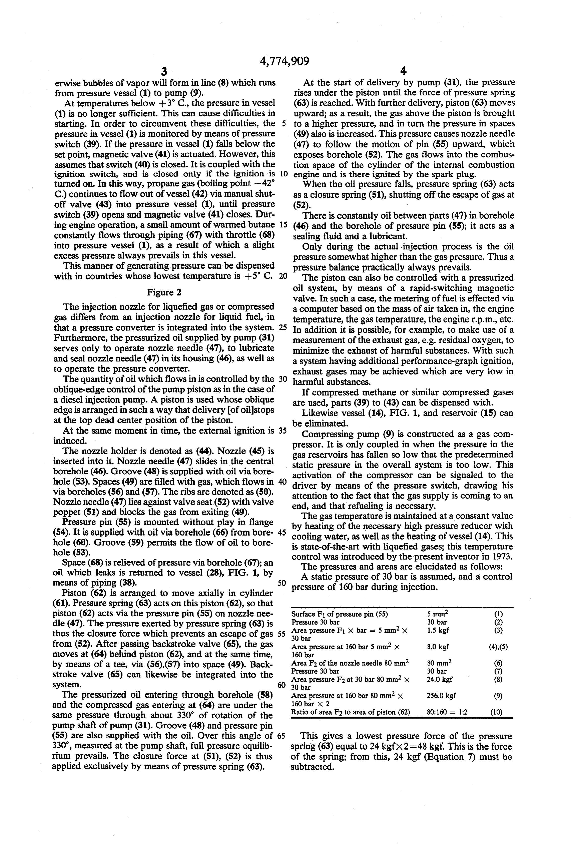
The injection nozzle for liquefied gas or compressed a computer based on the mass of air taken in, the engine gas differs from an injection nozzle for liquid fuel, in temperature, the gas temperature, the engine r.p.m., etc. that a pressure converter is integrated into the system. 25 In addition it is possible, for example, to make use of a Furthermore, the pressurized oil supplied by pump (31) measurement of the exhaust gas, e.g. residual oxygen, to serves only to operate nozzle needle (47), to lubricate minimize the exhaust of harmful substances. With such and seal nozzle needle (47) in its housing (46), as well as a system having additional performance-graph ignition, to operate the pressure converter. exhaust gases may be achieved which are very low in The quantity of oil which flows in is controlled by the 30 harmful substances.
oblique-edge control of the pump piston as in the case of If compressed methane or similar compressed gases a diesel injection pump. A piston is used whose oblique are used, parts (39) to (43) can be dispensed with. edge is arranged in such a way that delivery of oilstops Likewise vessel (14), FIG. 1, and reservoir (15) can at the top dead center position of the piston. be eliminated.
At the same moment in time, the external ignition is 35 Compressing pump (9) is constructed as a gas com induced. pressor. It is only coupled in when the pressure in the The nozzle holder is denoted as (44). Nozzle (45) is gas reservoirs has fallen so low that the predetermined inserted into it. Nozzle needle (47) slides in the central borehole (46). Groove (48) is supplied with oil via bore static pressure in the overall system is too low. This activation of the compressor can be signaled to the hole (53). Spaces (49) are filled with gas, which flows in driver by means of the pressure switch, drawing his
via boreholes (56) and (57). The ribs are denoted as (50). attention to the fact that the gas supply is coming to an Nozzle needle (47) lies against valve seat (52) with valve end, and that refueling is necessary. poppet (51) and blocks the gas from exiting (49).
Pressure pin (55) is mounted without play in flange byThe gas temperature is maintained at a constant value heating of the necessary high pressure reducer with (54). It is supplied with oil via borehole (66) from bore 45 hole (60). Groove (59) permits the flow of oil to bore cooling water, as well as the heating of vessel (14). This is state-of-the-art with liquefied gases; this temperature
Space (68) is relieved of pressure via borehole (67); an controlThe was introduced by the present inventor in 1973.
pressures and areas are elucidated as follows:
oil which leaks is returned to vessel (28), FIG. 1, by A static pressure of 30 bar is assumed, and a control means of piping (38). 50 pressure of 160 bar during injection.
Piston (62) is arranged to move axially in cylinder (61). Pressure spring (63) acts on this piston (62), so that piston (62) acts via the pressure pin (55) on nozzle nee Surface F of pressure pin (55) 5 mm. (1) dle (47). The pressure exerted by pressure spring (63) is Area Pressure 30 bar 30 bar (2) thus the closure force which prevents an escape of gas 55 30 barpressure F X bar = 5 mm x 1.5 kgf (3) from (52). After passing backstroke valve (65), the gas Area pressure at 160 bar 5 mm x 8.0 kgf (4),(5) moves at (64) behind piston (62), and at the same time, 160 bar by means of a tee, via (56),(57) into space (49). Back Area F2 of the nozzle needle 80 mm Pressure 30 bar
30 bar
stroke valve (65) can likewise be integrated into the Area pressure F2 at 30 bar 80 mm x 24.0 kgf (8) system. 30 bar
The pressurized oil entering through borehole (58) Area pressure at 160 bar 80 mm x 256.0 kgf (9) and the compressed gas entering at (64) are under the Ratio 160 bar x 2
same pressure through about 330 of rotation of the pump shaft of pump (31). Groove (48) and pressure pin (55) are also supplied with the oil. Over this angle of 65 This gives a lowest pressure force of the pressure 330, measured at the pump shaft, full pressure equilib spring (63) equal to 24 kgfx2=48 kgf, This is the force rium prevails. The closure force at (51), (52) is thus of the spring; from this, 24 kgf (Equation 7) must be applied exclusively by means of pressure spring (63). subtracted.
Page 8
The factor 2 in equation (9) results from the area ratio the direction (64) opposite to the spring force (63). In in equation (10). this way, after closing of backstroke valve (65), the The system described here for blowing in or injecting pressure in gas spaces (49) is increased. This is governed compressed gases or liquefied gases requires only a by the ratio of the area of piston (62) to that of nozzle slight change in the existing structural components 5 needle (47).
which have proven useful through decades of opera Despite the rise in pressure underneath piston (62), tion. The problems of sealing and lubrication are solved; the motion causes pressure pin (55) to become un here the fact that the pressure on the gas side is equal to loaded, and it moves in direction (64). This motion is the pressure on the oil side is of enormous significance. followed by nozzle needle (47), and the fuel can flow The oil cannot be displaced by the gas, and the equal 10 out at (52).
pressure means that a diffusion of the gas into the oil is Owing to the control action of pump (31), the pres minimized. Owing to the internal pressure conversion, sure of the pressurized oil drops precipitously at the the injection pressure or the pressure of blowing gas in top-dead-center position of the piston of pump (31); the is increased in proportion to the area ratio. In this way, pressure of the gas in space (49) below nozzle needle the control oil pressure can be kept low. This control (47) becomes smaller, so that nozzle needle (47) blocks pressure basically determines the power consumption of off the escape of gas at (52) under the action of closure pump (31). spring (63). Any leak oil flowing out into space (68) is The problem of cold starting at temperatures below carried to (28) by means of piping (38).
5 C. and with butane as the fuel gas is solved by pres A constant amount of warmed gas is returned via surizing of pressure vessel (1) by means of the low-boil 20 throttle (67) to pressure vessel (1) by means of piping ing propane (boiling point -42 C.) in gaseous form. (66), so that the gas in (1) is constantly brought to a The boiling and evaporation of butane in the strongly temperature which is above the boiling point of the gas heated injection nozzle (34) is avoided by having a in vessel (1). In this way the consumption of propane minimum pressure of 20 bar in the system. from vessel (42) is limited.
The different density ofbutane (liquid phase) is elimi 25 The propane content of vessel (42) is indicated in nated by heating in vessel (14). Until the predetermined kilograms. One kg of propane, when decompressed to temperature is reached at (20), the quantity injected is normal pressure, produces 526 liters of gaseous pro greater, in terms of weight; this manifests itself in the pane. The consumption of propane in a cold start is thus form of a slightincrease in efficiency during a cold start. relatively small. It depends on the filling level of vessel This is desirable, since the frictional values of the engine 30 (1). The gaseous propane dissolves in liquid butane in are higher in a cold start. The exhaust gases then have vessel (1) and is combusted along with it. a somewhat higher content of harmful substances. This system of internal mixture formation can also be The system works as follows: used for liquid fuels such as alcohols or gasoline. Initial startup Owing to the metering of gas in the form of an inter 35 nal mixture formation, a so-called "layer-load opera
Valve (34) on vessel (42) is opened; magnetic valve tion' is achieved, whereby the harmful substances in (42) is actuated by closure of switch (40). As long as the exhaust gases are greatly reduced. Freedom from pressure switch (39) is closed, propane gas flows from soot and sulfur is attained with gas operation. It is thus (42) into pressure vessel (1). Liquid phase flows into the possible to replace diesel operation with gas operation, system via (3) by means of an auxiliary electrical circuit, 40 without a significant increase in technical expense. Soot by the actuation of (7). filters are dispensed with completely. The overall gas system is degassed as far as back Away is shown here either to completely avoid emis stroke valve (65), so that liquid phase is present in the sions of harmful substances such as occur in diesel oper system. ation (smoke, SO2), or to reduce to a minimum the Reservoir (25) is filled with pressurized oil from (28) 45 emission of harmful substances in the form of aromatics by means of hand pump (27); this can be observed and nitrogen oxides.
through (26). Then the total pressurized oil system is The operation with compressed natural gas is based deaerated in known manner as far as nozzle (34). on an existing supply network for compressed natural After the auxiliary electrical circuits are shut off, the gas in Europe having a supply pressure of at least 40 engine is started. 50 bar, so that it is only necessary to provide refueling Normal operation, gas temperature >5 C. capabilities in the form of compressors for raising the pressure from 40 bar to 300 bar, including the necessary
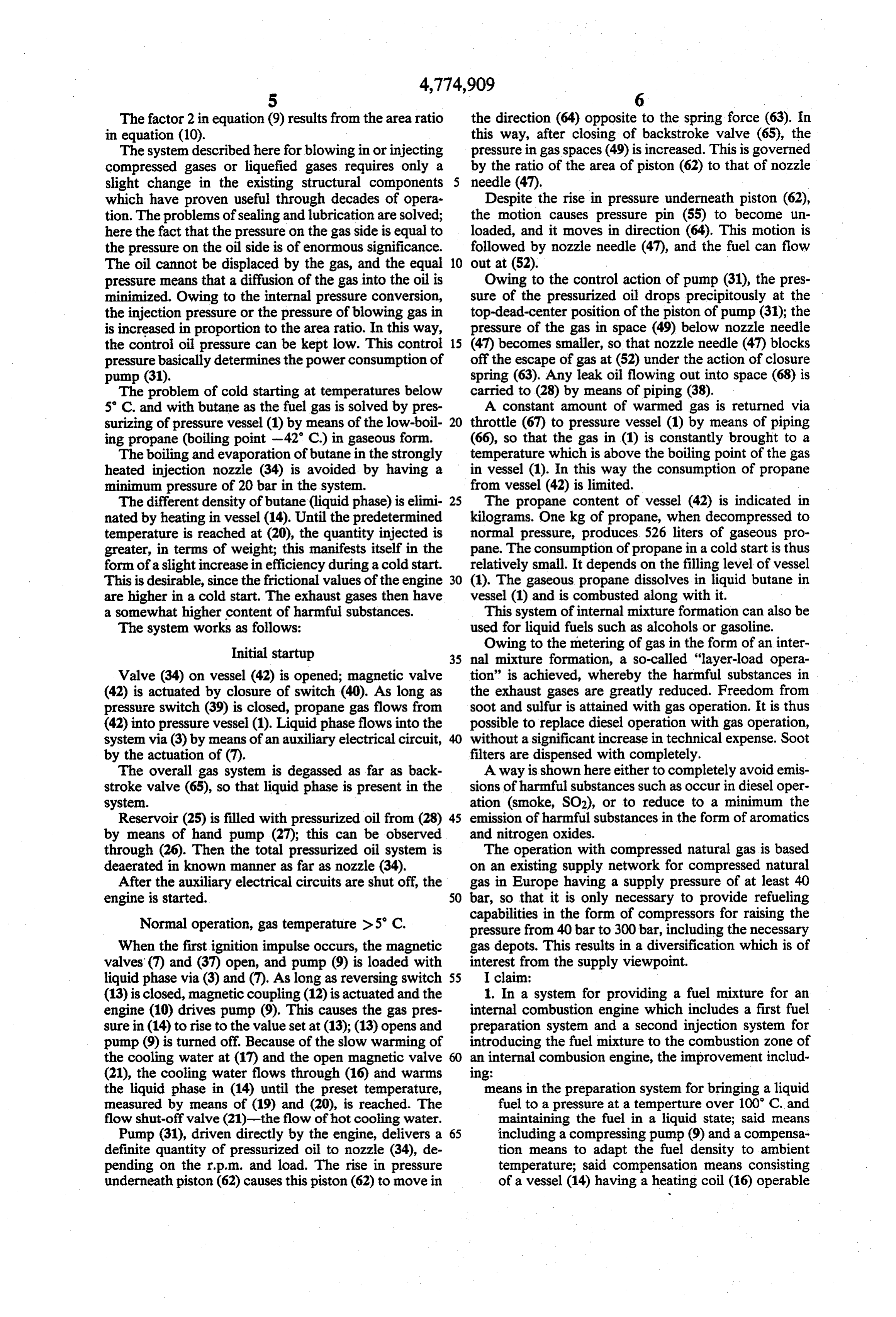
When the first ignition impulse occurs, the magnetic gas depots. This results in a diversification which is of valves (7) and (37) open, and pump (9) is loaded with interest from the supply viewpoint.
liquid phase via (3) and (7). As long as reversing switch 55 I claim:
(13) is closed, magnetic coupling (12) is actuated and the 1. In a system for providing a fuel mixture for an engine (10) drives pump (9). This causes the gas pres internal combustion engine which includes a first fuel sure in (14) to rise to the value set at (13); (13) opens and preparation system and a second injection system for pump (9) is turned off. Because of the slow warming of introducing the fuel mixture to the combustion zone of the cooling water at (17) and the open magnetic valve 60 an internal combusion engine, the improvement includ (21), the cooling water flows through (16) and warms 1ng:
the liquid phase in (14) until the preset temperature, means in the preparation system for bringing a liquid measured by means of (19) and (20), is reached. The fuel to a pressure at a temperture over 100 C. and flow shut-off valve (21)-the flow of hot cooling water. maintaining the fuel in a liquid state; said means Pump (31), driven directly by the engine, delivers a 65 including a compressing pump (9) and a compensa definite quantity of pressurized oil to nozzle (34), de tion means to adapt the fuel density to ambient pending on the r.p.m. and load. The rise in pressure temperature; said compensation means consisting underneath piston (62) causes this piston (62) to move in of a vessel (14) having a heating coil (16) operable
Page 9
by means of cooling water recirculated from the approximately the same quantity of liquid control pres engine (10), which vessel is connected in series sure oil and liquid fuel, respectively, are present. after the compressing pump (9), and in which the 11. A system in accordance with claim 10 in which a fuel is heated such that the fuel temperature is gaseous fuel is introduced and pressure vessel (23) is above the ambient temperature, and said compen 5 subjected to the gas pressure on one side. sation means further includes a thermostat and 12. A system in accordance with claims 10 or 11 in magnetic valve in the heating coil circuit, by which which the means for equalizing pressure equalizes pres the temperature is regulated; sure of the control oil, the metering pump, piping (32) a metering pump for providing a predetermined con and the metering portion of the injection vaive, and the trol oil pressure for regulating the introduction of O pressure is maintained equally as the fuel pressure fuel into the engine and an injection valve (34) in which exists at the cylinder in the engine to which the the injection system and means for operatively fuel is injected.
interconnecting the pressure of the vessel, the pres 13. A system in accordance with claim 1 in which the sure of the fuel introduced by the injection valve metering pump (31) has a diagonal-edge control means, and the control oil pressure from the metering 15 via piping (32), connection (58) and borehole (60) on pump, piston (62) in the engine, which means can move axially whereby the control oil pressure and the pressure of in the engine cylinder (63), whereby the quantity of the fuel mixture in the preparation system are the control oil required for injection is provided by the same except when fuel is injected into the combus metering pump means.
14. A system in accordance with claim 1 in which the 2. A system in accordance with claim 1 including a injection valve is formed in a housing (44) and includes nozzle needle reciprocably mounted in a borehole in the a nozzle needle injection system in which the needle and borehole are der combustion (47), operatively disposed in the cylin zone, which zone is filled with fuel lubricated and sealed at the same time, and lubricating oil is maintained between said needle and borehole in 25 under pressure and which nozzle needle (47) is sub said means as a result of the equality of pressure of the jected to pressurized oil by means of borehole (56) and (66) groove (48) in the housing, and in which the pres fuel and the control oil.
3. A system in accordance with claim 1 in which the surized oil has the same pressure as the fuel in the com equalization of the pressure of the control oil and the bustion zone (49) and in which the nozzle needle (47) is lubricated in its borehole (46), and is sealed by the pres fuel oil minimizes the diffusion of the fuel into the con 30 trol oil. surized oil.
4. A system in accordance with claim 2 in which the 15. A system in accordance with claim 1 including a equalization of the pressure of the control oil and the pressure pin (55) in an operative relationship with a fuel oil minimizes the diffusion of the fuel into the con nozzle needle in the injection systems, which pin is trol oil. 35 guided into an intermediate flange (54) and subjected to 5. A system in accordance with claim 1 in which the pressurized oil via borehole (66), so that the pressurized compressing pump in the fuel preparation system is oil effects lubrication and sealing of the combustion driven by the engine and the pump includes a pressure ZOc.
switch to maintain the pressure in the vessel constant, 16. A system in accordance with claim 1 in which the which pressure switch (13), when a preset pressure is 40 nozzle needle (47) includes a deaeration means. reached, deactuates the compressing pump by means of 17. A system in accordance with claim 15 in which a magnetic coupling (12). the nozzle needle (47) includes a deaeration means. 6. A system in accordance with claim 1 including 18. A system in accordance with claim 1 including a means by which the compressing pump is switched over pressure spring (63) and piston (62), guided in an engine to a pressure-free rotation by means of a storage-load 45 cylinder (61), operatively interconnected with a pres valve when a pre-set pressure is reached. sure pin (55), whereby the pressure of the pressure 7. A system in accordance with claim 5 including a spring (63) acts as a closure pressure on a nozzle needle storage-load valve by which the compressing pump is of the injection system (47) and further including a switched over to pressure-free rotation. valve poppet (51) on the nozzle needle to prevent an 8. A system in accordance with claim 1 in which the 50 escape of fuel from the injection system. vessel (14) includes a pressure reservoir (15) which 19. A system in accordance with claim 15 including a maintains the fuel pressure in the system connected in pressure spring (63), and piston (62), guided in cylinder series with the vessel (14) when the engine is stopped, (61), operatively interconnected with the pressure pin and a backstroke valve (33) by which an outflow in the (55), whereby the pressure of the pressure spring (63) direction of pump (9) is prevented. 55 acts as a closure pressure on the nozzle needle (47) and 9. A system in accordance with claim 1 in which the further including a valve poppet (51) on the nozzle fuel under pressure in the vessel (14) is heated by means needle to prevent an escape of fuel from the injection of the engine cooling system from which water is with system.
drawn and circulated and the vessel further includes a 20. A system in accordance with claim 1 including sensor (19) and a thermostat (20) in a control rerlation 60 boreholes in the engine which provide a means for ship with a magnetic valve (21) connected to the engine conveying the control oil pressure. cooling system, so that the temperature of the fuel in 21. A system in accordance with claim 1 having a vessel (14) remains approximately constant. piston and nozzle needle in the injection system in 10. A system in accordance with claim 1 further in which the ratio of the areas of the cross section of piston cluding a pump (27) and a further oil containing vessel 65 (62) to the cross section of nozzle needle (47) is 2:1, (28) having a sight glass (29), whereby the fuel pressure whereby an internal pressure elevation of oil relative to is exerted on one-half of pressure vessel (23) at (24), and fuel occurs in (34) owing to the metering oil pressure of sufficient oil is pumped into the other half at (25), until pump (31).
Page 10
9 O 22. A system in accordance with claim 14 having a 30. A system in accordance with claim 1 including a piston in the injection system in which the ratio of the source ofbutane as a fuel and in which gaseous propane areas of the cross section of piston (62) to the cross is fed to vessel (1) from pressure bottle (42) attempera section of nozzle needle (47) is 2:1, whereby an internal tures slightly above the boiling point of the butane or pressure elevation of oil relative to fuel occurs in (34) below, via pressure switch (39), ignition switch (40) and owing to the metering oil pressure of pump (31). magnetic valve (41), so that the formation of vapor 23. A system in accordance with claim 19 in which bubbles in piping (8) is prevented as a result of the ex the ratio of the areas of the cross section of piston (62) cess pressure in vessel (1).
31. A system in accordance with claim 10 including a to the cross section of nozzle needle (47) is 2:1, whereby 10 compressing pump driven by an electric motor and an internal pressure elevation of oil relative to fuel oc means for controlling said compressing pump compris curs in (34) owing to the metering oil pressure of pump ing a filling level sensor in vessel (23). (31). 32. A system in accordance with claim including a 24. A system in accordance with claim 20 in which gaseous fuel source in the form of high-pressure gases the ratio of the areas of the cross section of piston (62) 15 such as methane, sewer gas, depot gas and similar gases to the cross section of nozzle needle (47) is 2:1, whereby and further including means to lower the pressure of the an internal pressure elevation of oil relative to fuel oc gases comprising a first pressure reducer located within curs in (34) owing to the metering oil pressure of pump the high-pressure vessel to reduce the vessel pressure to (31). the operating pressure of the system, and a fine-pressure 25. A system in accordance with claim 1 including a regulator connected in series after the vessel. leak removal system in which leaking gas is collected 33. A system in accordance with claim 32 including a into vessel (28) via the leak removal system during the fine-pressure reducer that is heated by means of cooling operation of the combustion engine with gaseous fuels water and regulated by a thermostat, in a manner such and is exhausted to the intake air in the intake zone of that the temperature of the exiting fuel gas is help ap the internal combustion engine. 25 proximately constant.
26. A system in accordance with claim 17 including a 34. A system in accordance with claim 5 in which the leak removal system in which leaking gas is collected compressing pump (9) is a compressor which becomes into vessel (28) via the leak removal system during the system pressuremeans operational by of pressure switch (13) when the operation of a combustion engine with gaseous fuels and 30 the exit side of thereaches approximately the pressure at pressure reducer, and the high pres is exhausted to the intake air in the intake zone of the internal combustion engine. . sure vessel can be almost emptied, whereby the pressure 27. A system in accordance with claim 1 including reducer integrated into the high pressure vessel and allows the stored gas to flow out completely, since the means for electromagnetically metering pressurized oil pressure in front of this pressure reducer is smaller than which means is controlled by a computer. 35 the pressure set for the exit side of the pressure reducer. 28. A system in accordance with claim 13 including 35. A system in accordance with claim 5 including a means for electromagnetically metering pressurized oil means for signaling an operator, in correspondence which means is controlled by a computer. with the switching function of pressure switch (13) so . 29. A system in accordance with claim 27 in which a that the operator is informed that the fuel supply is piezoelectric actuator is the means for metering of pres 40 falling and that refueling is required. surized oil. is
Provenance
- Collection
- Cited prior art
- Original PDF
- patentimages.storage.googleapis.com →
- Filed
- 1986-11-13
- Pages
- 10
- Method
- pdftotext (the PDF's own text layer) + pdftoppm 300dpi page scans
- Source
- Google Patents bibliographic record
- Granted
- 1988-10-04
- Inventors
- Erich A. Dolderer
- Transcribed from
- patentimages.storage.googleapis.com →