patent · US4750454
Manure digester and power generating system
14 June 1988
Page 1 — bibliographic record
United States Patent (19) 11 Patent Number: 4,750,454 Santina et al. - (45) Date of Patent: Jun. 14, 1988 54) MANURE DIGESTER AND POWER 4,274,838 6/1981 Dale et al. ........................... 435/316 GENERATING SYSTEM 4,372,856 2/1983 Morrison ..... ..., 210/180 4,401,441 8/1983 Chase .................................... 48/111 (75) Inventors: Peter F. Santina, Walnut Creek; Anil 4,437,987 3/1984 Thornton et al. ................... 435/316 K. Chatterjee, Newark, both of Calif.
FOREIGN PATENT DOCUMENTS
73 Assignee: Santina and Thompson, Inc.,
Concord, Calif. 0051941 5/1982 European Pat. Off. ............ 435/287 21 Appl. No.: 922,795 Primary Examiner-Peter Kratz Attorney, Agent, or Firm-Thomas M. Freiburger
- Related U.S. Application Data A manure digester and power generating system in 63 Continuation of Ser. No. 621,223, Jun. 15, 1984, aban cludes a mixing tank for receiving manure, a closed, doned. anaerobic manure digester tank of fixed volume, and a 51) Int. Cl."...................... F02B 43/08; FO2M 21/02; gas-fueled engine and a generator coupled to the engine, C12M 1/02 for generating electrical power. Manure is scraped into 52 U.S. Cl. .......................................... 123/3; 48/111; the mixing tank daily, where it is mixed with water to 210/170; 210/180; 210/232; 210/257.1; produce a manure slurry of desired consistency, and 210/.532.2; 435/167; 435/316 heated to a prescribed temperature. The digester tank is 58) Field of Search ............. 48/111, 197 A; 435/167, of fixed volume and may be of a generally rounded 435/287, 316, 317; 123/3; 210/170, 180, 232, cross-sectional shape and elongated in length, and into 257.1, 532.2, 614 its inflow end the contents of the mixing tank are trans (56) References Cited ferred daily, on a daily batch basis. Anaerobic-digesting microbes are maintained in the digester tank to digest
1,314,955 9/1919 Flicker ................................ 435/167 ducts. Temperature in the digester tank is maintained at 3,591,492 7/1971 Neuspiel. ... 210/257. about 90 to 100 F. Effluent by-products are dis 3,939,806 2/1976 Bradley ................................... 123/3 charged out the outflow end of the digester tank, and 3,968,775 7/1976 Hayman .................................. 123/3 methane gas is drawn off the digester tank and fed to the 3,981,800 9/1976 Ort ...................................... 430/167 gas-fueled engine, the exhaust heat from which prefera 4,057,401 11/1977 Boblitz. .................................. 48/11 4,166,835 9/1979 Anderson . 435/316 bly is used to heat the slurry in the mixing tank. 4,209,303 6/1980 Ricks ... 435/316 4,230,580 10/1980 Dodson ............................... 210/180 9 Claims, 8 Drawing Sheets
SOLD O BY-PRODUCTS 6 13
SOLDS
SEPARATOR
PLUG FOW
DGESTER
STORAGE
RESERVOR
GENERATOR
ENERGY FOR FARM USE
OR SALE TO UTILITY
Page 2
Drawing sheet — no readable text.
Page 3
Drawing sheet — no readable text.
Page 4
Drawing sheet — no readable text.
Page 5
Drawing sheet — no readable text.
Page 6
Drawing sheet — no readable text.
Page 7
Drawing sheet — no readable text.
Page 8
Drawing sheet — no readable text.
Page 9
Drawing sheet — no readable text.
Page 10
mum gas production. Often the prior systems were on a
MANURE DIGESTER AND POWER GENERATING batch process, with new manure slurry added on a peri SYSTEM odic batch-by-batch basis. Digester tanks of various configurations have been suggested. The waste heat
This is a continuation of co-pending application Ser. 5 from a methane gas-fueled engine fed by the digestion No. 621,223 filed on June 15, 1984, now abandoned. process has sometimes been used for heating the manure BACKGROUND OF THE INVENTION slurry in the digester.
However, none of the prior art systems contemplated
The invention relates to manure digestion to produce or suggested the efficient combination of features of the methane gas, which may be used directly for process 10 present invention described below, for optimizing heat or to fuel an engine/generator to produce electri power output in a manure digesting/power generating cal power. system which is versatile, reliable and relatively simple The extraction of energy from wastes using anaerobic in construction and arrangement.
digestion is old, and the general technology is known. It SUMMARY OF THE INVENTION has been used to treat sewage sludge, and often the 15 resulting biogas has been used to maintain the digester The manure digester and power generating system of temperature, to run internal combustion engines, etc. the present invention optimizes gas production by pre Many small units were used in France and Algeria after heating a manure/water slurry of optimum consistency World War II, and in India and China, many homes and and maintaining the slurry within an optimum tempera farms have used biogas for everyday activities such as 20 ture range through a plug flow or batch flow digester of cooking, hot water heating, etc. fixed volume. Electrical power may be generated using Anaerobic digestion is a microbial process involving the gas or the gas may be used directly for process biochemical decomposition of organic material such as heating or other heating purposes at the site, or the gas animal manures in the absence of oxygen. It is a two may be transmitted to other locations. stage decomposition process. A specific group of micro 25 The system of the invention includes a mixing tank organisms convert the complex organic matter present for receiving manure dropped into the tank, with means in the farm animal manure into methane and other for mixing water with the manure to produce a manure gases. The first stage of this biochemical conversion slurry of desired consistency, and means for heating the process produces simple organic acids by acid-forming slurry in the mixing tank. The heated, mixed slurry is bacteria. In the second stage, mathane-forming bacteria pumped, on a periodic batch-by-batch basis, into a consume and break down the acids into methane and closed, anaerobic digester tank of fixed volume, elon carbon dioxide gases. Only a properly designed digester gated in length, and free of sharp corners internally, can claim to achieve the balance of the two groups of with means for maintaining anaerobic-digesting mi bacteria so that the methane-formers use all the acids crobes therein to digest the manure slurry and produce produced by the acid-formers. This balancing can only 35 methane gas and by-products. The digester tank is insu be achieved by controlling the nutrient loading rate, lated for retention of heat during the digestion process. retention time, mixing and temperature. Effluent solid and liquid by-products are discharged out There are various environmental parameters such as the outflow end of the digester tank, for use as fertilizer, pH, volatile acid concentration, temperature, nutrient bedding materials or other uses. The system employs a availability, heating and heat balance that influence the 40 biogas-fueled engine and a generator coupled to the ability of the bacteria to produce optimum quantities of engine for generating electrical power, and means for biogas. Two distinct temperature ranges offer optimum drawing off methane gas from the digester tank and conditions for bacterial growth in the anaerobic diges conducting it to the engine as fuel. tion process. The mixing tank preferably is efficiently heated by The first is mesophilic range, (85 F-110 F) and the 45 circulation of waste heat from the biogas-fueled engine second is the thermophilic range, (110 F-150 F). through the tank, which may be via hot water in pipes Although higher biogas production has been reported passing through the tank and contacting the slurry. For from digesters operating in the thermophilic range, the optimum heating efficiency, heat exchange jacket water active bacteria are more sensitive to environmental from the engine is put through a preliminary heat ex conditions than mesophilic bacteria and therefore com 50 changer where it is further heated by the hotter exhaust mercial scale digester control operation becomes too gas from the engine. The enginejacket water so heated critical. Moreover, considerable energy input is needed by the exhaust gas, then exchanges heat with cooler to maintain the digester in the thermophilic range. mixing tank heat exchanger recirculation water in a The mesophilic anaerobic digester of the present second stage shell-and-tube heat exchanger. Tempera invention is structured to maintain the optimum balance 55 ture is thermostatically controlled by recirculating hot between the acid and methane former bacteria and jacket water through the engine radiator before it thereby to produce the maximum biogas from the diges reaches the second stage exchanger.
tion of the animal manures. The digester system may be for dairy cattle, swine, Various systems have been suggested for digesting poultry (chicken, turkey, ducks), or other livestock agricultural manure with microbes, collecting methane 60 which lend themselves to collection of manure from gas produced thereby, and using the gas to fuel an en one general area. In the case of diary cattle, the manure gine which drives a generator to produce electrical is scraped daily from alleyways of free stall barns into power. Some of these systems have employed expand the mixing tank, which may be open-topped at least at able covers on manure digester tanks or in-ground one side, for conveniently receiving the manure. The troughs, to accommodate variations in volume of gas 65 below-ground mixing tank, may have a liquid capacity being produced. See, for example, U.S. Pat. No. holding one day's production of manure. For example, 4,274,838. Some have used various means for maintain the mixing tank capacity for 500 cows digest system ing desired temperature in the digester tank, for opti may be about 10,000 gallons. The solids content is ad
Page 11
justed to appropriate slurry consistency required for screen or screw press or other solids separator, some optimum biochemical conversion mechanism by adding solids can be used as a fractional feed mix for refeeding water, the quantity of water depending upon the mois to the animals. It has been shown that such digester ture content of the daily manure. solids have the same value as alfalfa hay when mixed This manure/water mixture or slurry is thoroughly with fresh feed. The liquid portion of the effluent is an mixed using a specially designed slurry mixer in the excellent fertilizer, and can be applied to crops through tank. At the same time, the slurry is heated to approxi an existing irrigation system or spread by special tank mately 95 F. by the heat exchanger in the mixing tank, wagon. Digestion has the added benefit of reducing which preferably utilizes hot water from the gas en odors from the manure so that if the effluent is stored in gine's water jacket, optionally heated further by the O a lagoon, it is much less offensive than raw manure. engine's exhaust, and circulated directly or indirectly The biogas produced from anaerobic digestion has through the mixing tank heat exchanger. When the about 60% of the heat value of natural gas. The heat slurry in the mixing tank has reached 100 F., it is value of biogas can be as much as 600 BTU per cubic pumped to the digester. A thermostatically controlled foot, consisting of about 60% methane, 40% carbon switch may be provided to activate a submersible slurry 15 dioxide, and traces of ammonia and hydrogen sulfide. pump in the mixing tank for this purpose. When the The biogas slurry level in the mixing tank has dropped to a pre-set tending fromexits the digester tank through a pipe ex the top of the digester. Pressure within the level, the slurry pump is automatically switched off, digester is controlled by a relief valve mounted near the preferably by floating level switches. gas outlet line. The biogas moves through the pipe and According to the invention, cattle and poultry ma 20 through know devices required for handling this type of nure or other combinations may be mixed together to optimum proportions and digested in the mesophilic gas, which may include sedimental and drip tank, flame temperature range, 95° F.E.5 F. ordinarily used for arrestor and others. In some situations, a pressure stor age reservoir for biogas may be required.
cattle manure.
The digester employs the known plug flow digestion 25 The biogas may be used to fuel the engine generator concept, wherein fresh manure slurry is added daily at set to produce electricity, or used directly as fuel gas for one end of an elongated container and digested effluent process heat, in a number of different applications. In is removed at the other end. By maintaining a high total many states, public utilities are required to purchase solids content above 10% in the digester, mechanical excess electricity from smaller plants on a continuous mixing is not required, thus simplifying the digester 30 basis. Thus, no gas storage is required, and waste heat design for a dairy digester. However, for optimum fer from the continuing operation of the engine may be mentation and to prevent settlement of organics of poul used to heat the digester and for other heating uses. The try manures, a specially designed slow speed agitator electrical generator can be of the induction or synchro may be employed in the digester tank. nous type, suited for interconnection with the local The digester tank in one embodiment is constructed 35 utility. Electricity produced will provide a portion of or of double-walled fiberglass-reinforced-plastic or steel, all of the needs of the farm, thus reducing the electricity the walls being spaced apart with insulation between costs of the farming operation, and for periods of low them. The fiberglass or steel digester tank may be about farm use, surplus electricity is sold to the utility. 100 to 110 feet in length, with an ellipitical cross section, As mentioned above, the waste heat from the engine ... the major axis being horizontal, with dimensions, for 40 preferably is recovered from the water jacket of the example, of about 22 feet wide by 12 feet high. Such a engine and used for heating the mixing tank and also the digester configuration holds a total liquid volume of digester, on a back-up basis. Further, according to the about 134,000 gallons with 2 feet of gas space above the invention, waste heat is also recaptured from the higher liquid level. This results in a 15 to 20 day retention time temperature exhaust gas of the engine. for 7,000 to 8,000 gallons of slurry loaded daily. 45
The insulation in the digester tank reduces heat losses 500With the system of the invention, a dairy farm with head is able to generate enough methane to run a 50 so that slurry heated to 100 F., in the mixing tank is to 55 KW engine-generator set 24 hours per day. This maintained at an average temperature of 95 F. in the electricity may be sold directly to the utility. A greater digester tank, without any heat added on most days. For return is possible colder days, a back-up heat exchanger inside the di the diary farm's ifelectrical 50 the power produced is used to offset demand. Such an arrange gester may be used to maintain the optimum tempera ment can provide 90% to 100% of the digester system's ture.
In another embodiment, the digester may be an elon heating needs.
gated, poured-in-place concrete through with a maxi optimize It is therefore among the objects of the invention to mum length to width ratio of about 4. For example, a 30 55 efficiency, biogas production and electricity foot wide digester tank will have a total length of 120 production system, in a manure digester and power generating through the use of optimum tank configuration, feet. The digester tank may be provided with a sealed fiberglass-reinforced-plastic or steel cover made up of slurry heating and mixing arrangements, and other im portant features. These and other objects, advantages, sections secured together. features and characteristics of the invention will be When a batch of manure slurry is added to the di 60 apparent from the following description of a preferred gester from the mixing tank, the slurry level rises in the digester, and digested manure, called effluent, over embodiment, considered along with the accompanying flows and exits via a specially designed outlet chamber, drawings.
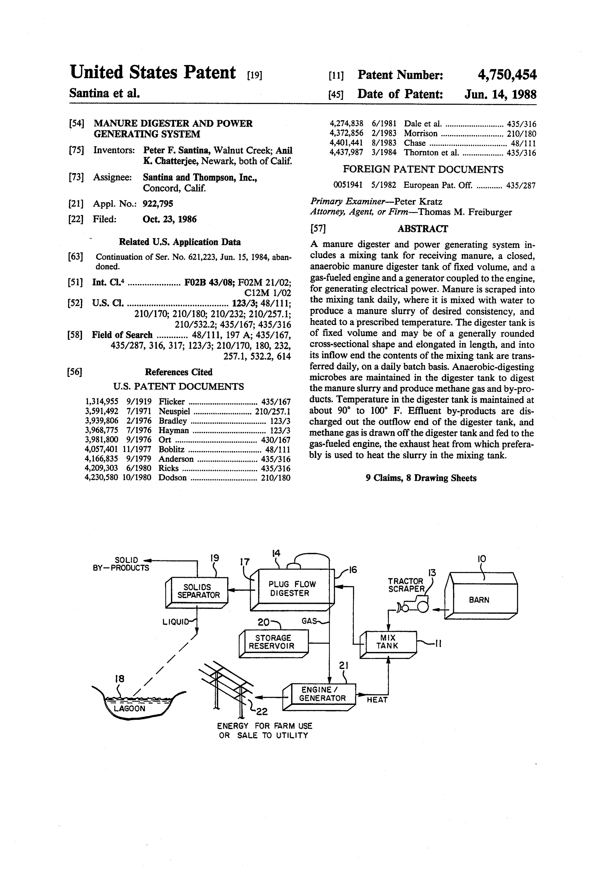
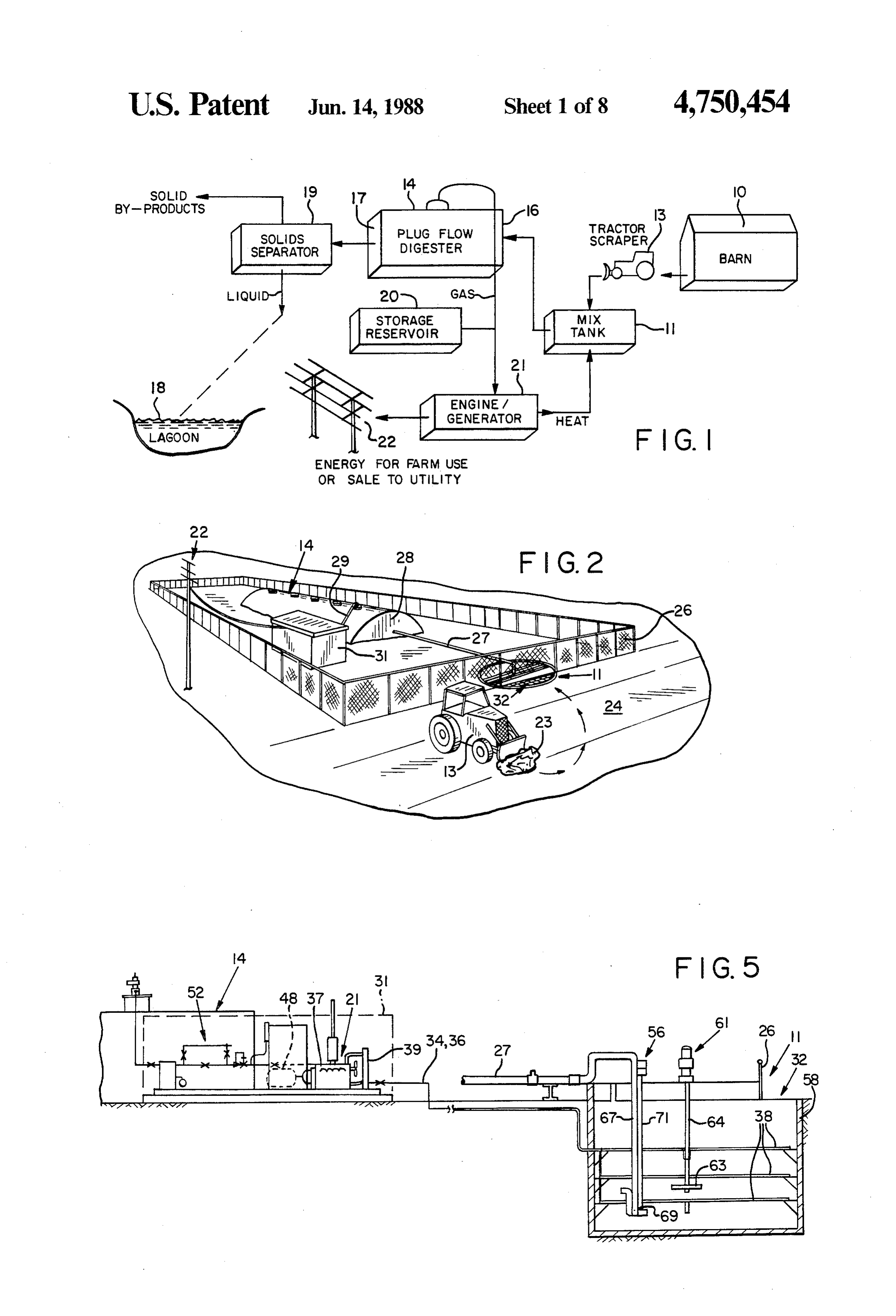
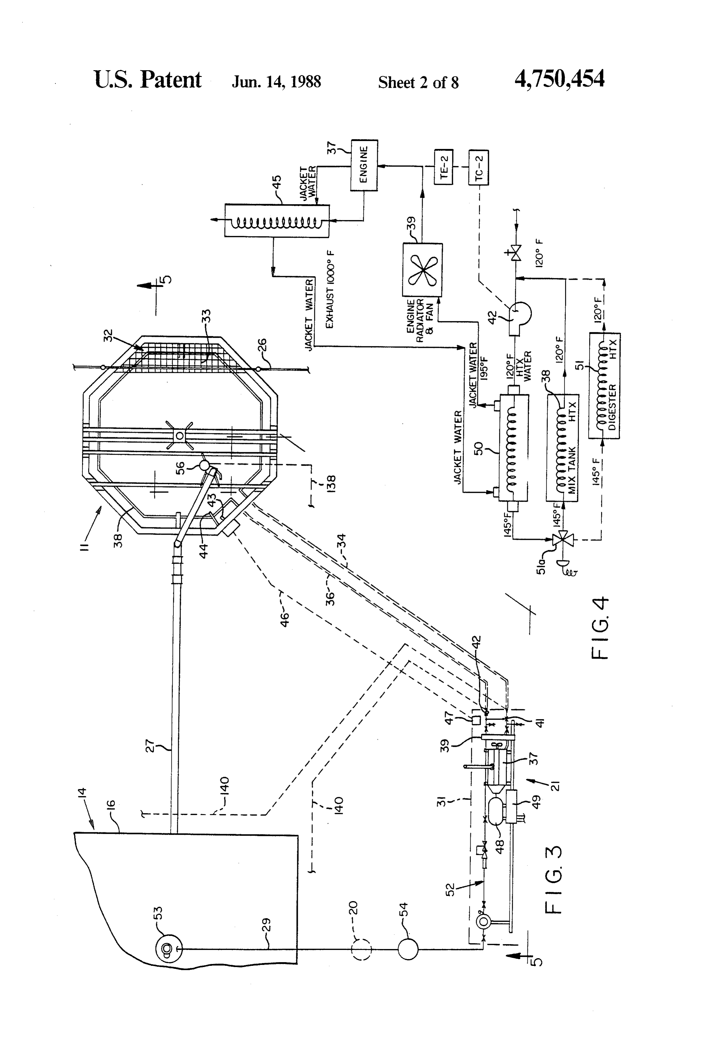
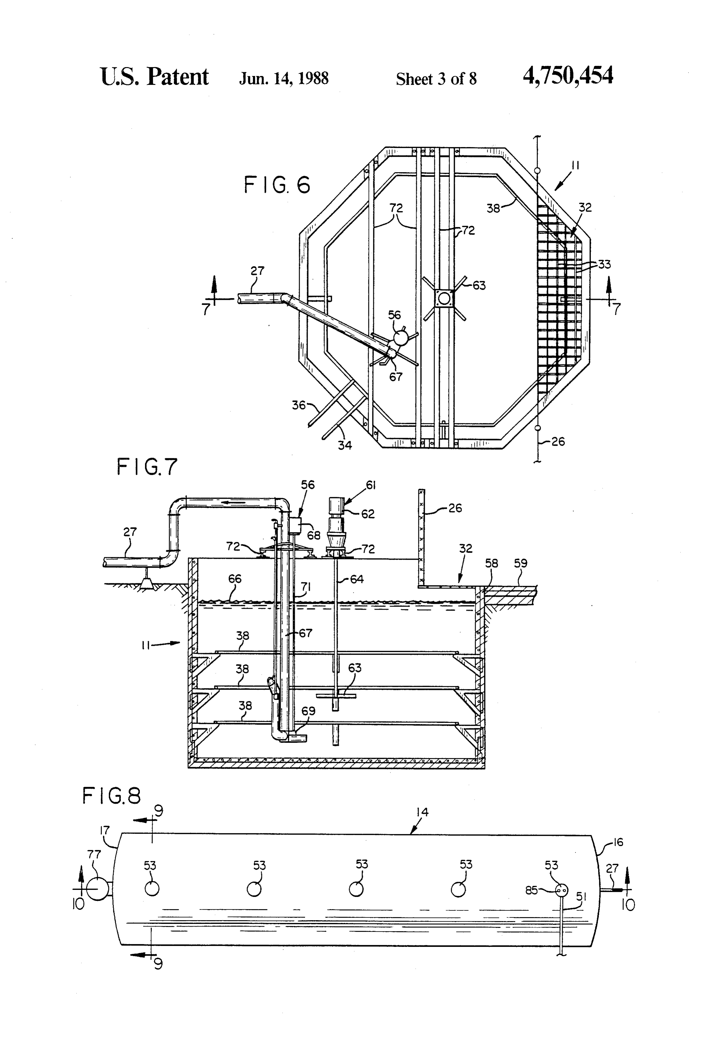
below the slurry level in the digester. Effluent flows DESCRIPTION OF THE DRAWINGS through the outlet chamber opening while maintaining 65 a gas-tight seal in the interior of the digester. The efflu FIG. 1 is a diagrammatic representation in the nature ent contains all the nitrogen, phosphorous and potas of a flow chart or block diagram indicating the steps sium of the original manure. If it is de-watered with a and major components of the system of the invention.
Page 12
FIG. 2 is a perspective view showing an example manure slurry at an inflow end 16, preferably on a daily arrangement of a diary manure digesting system of the batch-by-batch basis. The plug flow digester 14 is elon invention. gated, so that when the fresh manure slurry is added FIG. 3 is a plan view, partially schematic, showing daily at the inflow end 16, digested effluent exits the the layout of the mixing tank, the digester tank, the outflow end 17. The digested effluent may enter a la engine-generator set and the interconnection of these goon. 18, as indicated in FIG. 1, or may go directly to a components, relative to the system of the invention. solids separator 19 to have the liquid substantially re FIG. 4 is a block diagram showing the use of engine moved from the solids. The resulting liquids may be exhaust heat to augment the temperature of the water sprayed on crops as fertilizer through an irrigation sys from the engine's water jacket, for heating the manure 10 tem, or discharged to the lagoon, and the solids may be slurry in the mixing tank. used as fertilizer, bedding materials or bulk material for FIG. 5 is an elevation view, partially in section and feed.
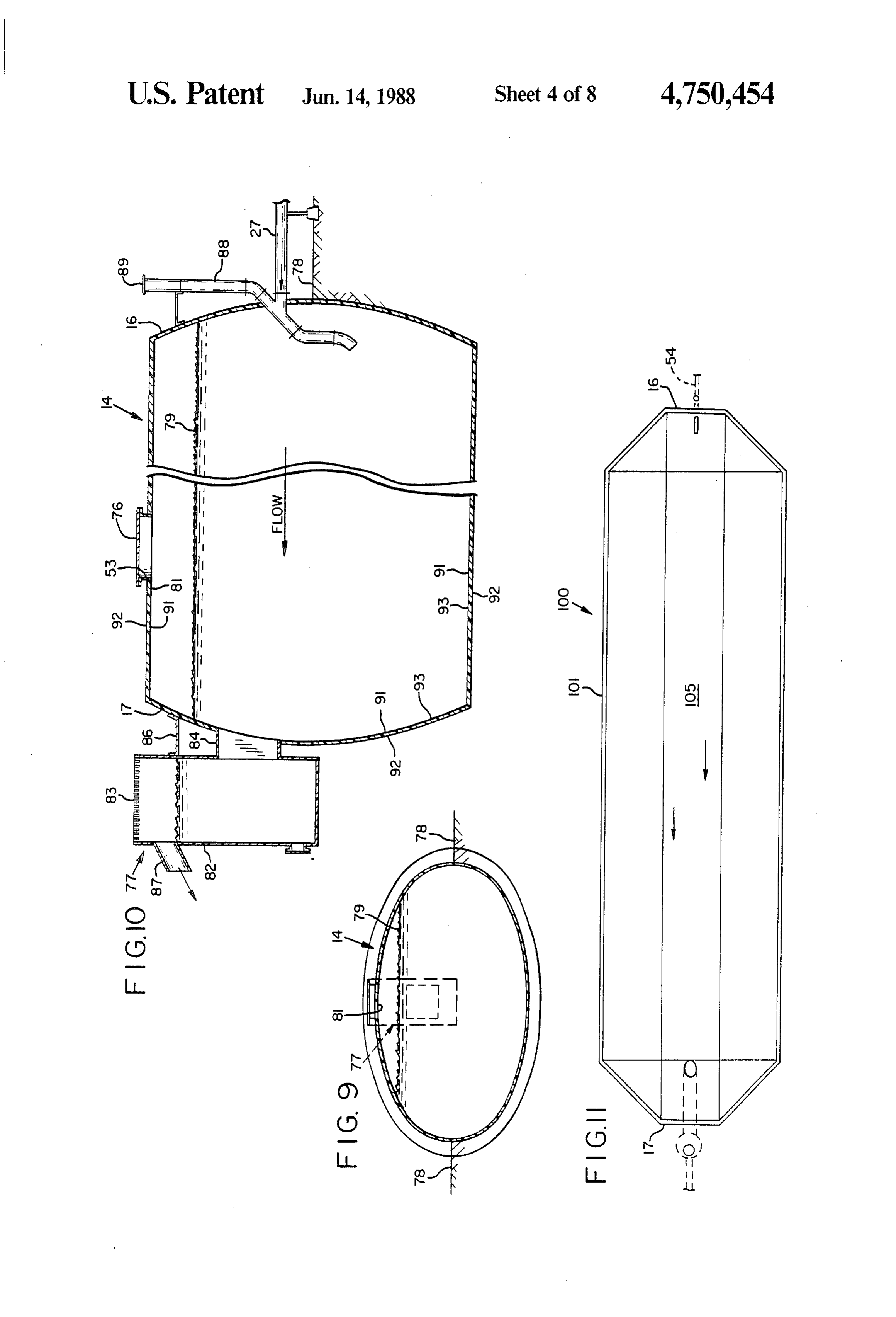
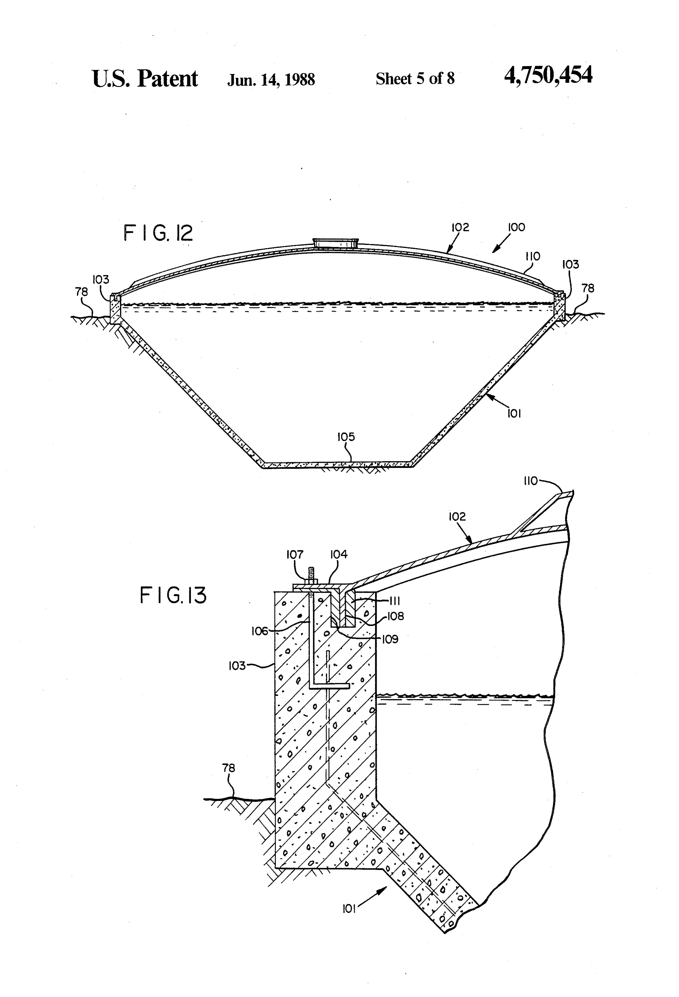
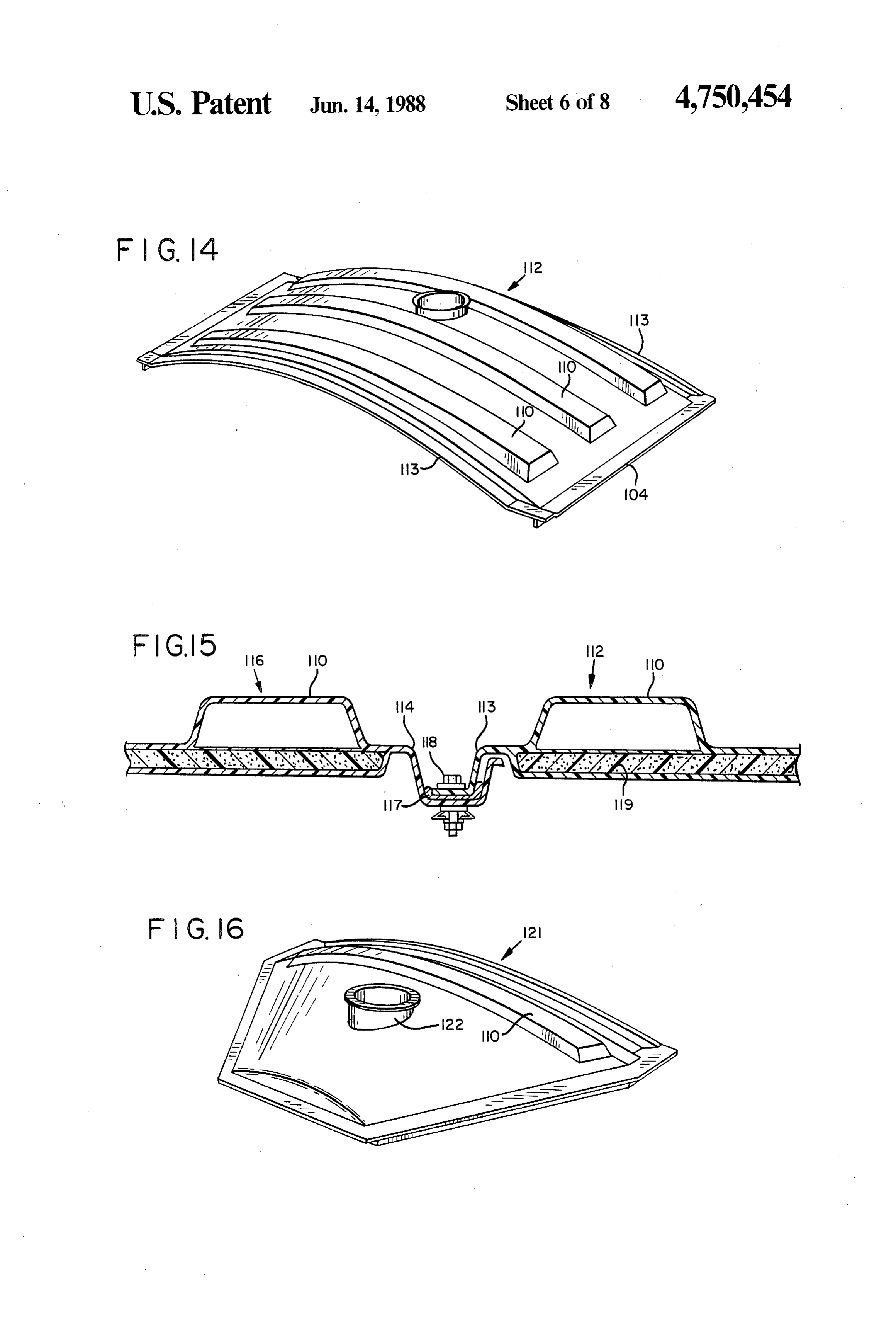
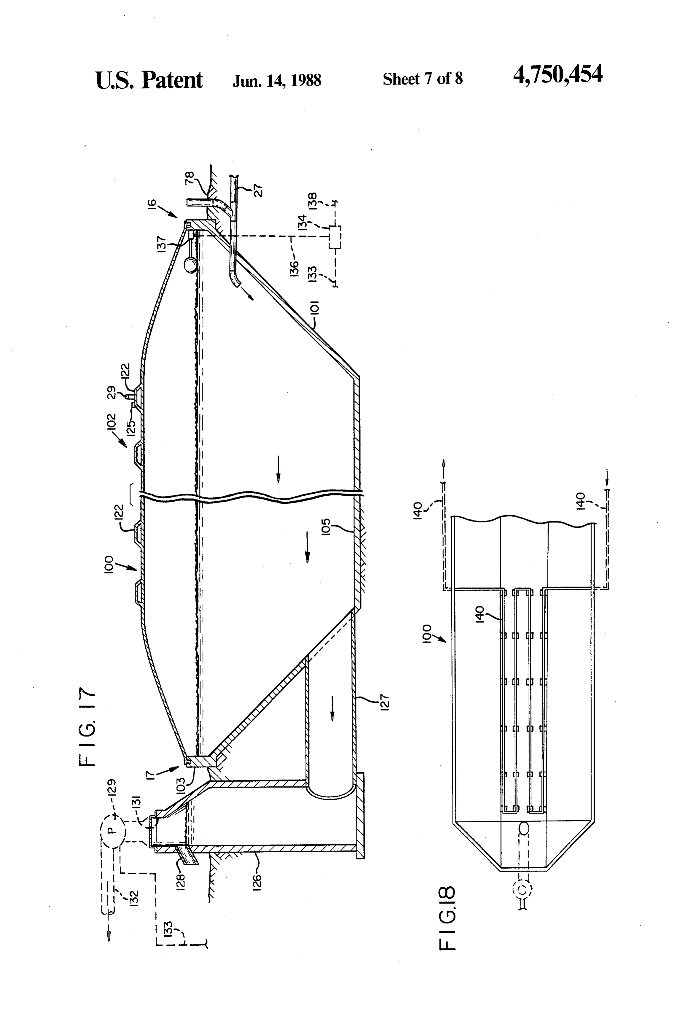
partially viewed underground, taken generally along As indicated in FIG. 1, biogas, principally methane the line 5-5 of FIG. 3. gas, is conducted from the digester tank 14 to an en FIG. 6 is a plan view showing the mixing tank in 15 gine/generator set 21, which uses the gas as fuel to greater detail. generate power for farm use and/or putting into the FIG. 7 is a sectional elevation view of the mixing utility power grid 22. For surplus gas storage, a pressure tank, as viewed along the line 7-7 in FIG. 6. reservoir 20 may be included. Heat from the engine of FIG. 8 is a plan view of the digester tank. the engine/generator set 21 is preferably delivered to FIG. 9 is a sectional elevation view of the digester 20 the mixing tank 11 for preheating of the manure slurry tank, as viewed along the line 9-9 in FIG. 8. within the tank. Thus, heat otherwise wasted is used FIG. 10 is a fragmented sectional elevation view of efficiently for slurry preheating. It is an important fea the digester tank, as viewed generally along the line ture of the invention that the manure slurry be pre 10-10 in FIG. 8. heated in the mixing tank 11, for optimum digestion and FIG. 11 is a plan view showing an alternate form of 25 production of gas in the digester 14, and the heating is digester tank. m most efficiently accomplished by use of engine heat. FIG. 12 is a partially diagrammatic sectional view of FIG. 2 shows generally the exterior appearance of the digester tank of FIG. 11. some of the components of the manure digester and FIG. 13 is an enlarged, detail sectional view showing power generating system of the invention. As illus a portion of the structure of the digester tank of FIG. 30 trated, the tractor scraper 13 scrapes manure 23 from an 11. alleyway 24, which may be of concrete and which is FIG. 14 is a perspective view showing a cover sec positioned to receive dairy manure dropped by cattle as tion of the digester tank of FIG. 11. they are feeding. The manure 23 is scraped and dumped FIG. 15 is a detail sectional view showing the manner into the mixing tank 11, a portion of which may extend in which two adjacent cover sections are connected. 35 outside a fence 26. The portion of the tank extending FIG.16 is a perspective view showing a special cover outside the fence 26 preferably is open-topped, or with section as occurs at the ends of the digester tank of FIG. a removable cover (not shown), so that the manure 11. scrapings can conveniently be dumped therein. FIG. 17 is a fragmented, partially schematic view in The manure slurry mixed and preheated in the mixing side elevation of the digester tank. tank 11 is conducted via a pipe 27 to the digester tank FIG. 18 is a schematic, partial plan view showing an 28, which preferably may be of an ellipitcal cross-sec arrangement of heat exchanger pipes in the digester tional shape, as described and illustrated below, accord tank. ing to one embodiment of the invention. The digester 28 FIG. 19 is a schematic logic diagram showing a con is approximately half below ground, as indicated in the trol system by which the system of the invention may be 45 drawing. Biogas produced in the digester 28 by anaero operated. bic digestion collects in the top approximately 2 feet of DESCRIPTION OF A PREFERRED the digester, under pressure, and flows through a con EMBODIMENT duit or pipe 29 to the engine/generator 21 housed within a shed 31 as shown. As shown in FIG. 1, the
In the drawings, FIG. 1 shows diagrammatically the 50 system may include a pressure reservoir 20 for storing method, apparatus and system of the present invention. surplus gas, particularly when the engine/generator set The system can be for a dairy farm or for poultry or any 21 is shut down.
other livestock wherein manure can be collected from FIG. 3 shows in plan view, partially schematic, the one general area, but it is described herein specifically manure digester and power generating system repre with respect to a dairy operation. The only differences 55 sented in FIGS. 1 and 2. The mixing tank 11 is shown between systems for dairy and poultry, for example, are partially extending beyond the fence 26, with its open principally in the operating parameters, size of tanks, portion 32 protected by a steel grid 33. The remainder etc. of the mixing tank 11 may be closed at its top to reduce Manure is scraped, preferably on a daily batch basis, heat losses, although no cover is shown in FIG. 3. The from a barn 10, a chicken coop or manure alleyway 60 mixing tank may be octagonal, as shown, to avoid sharp adjacent to where the livestock are fed, into a mixing internal corners where material may not mix properly. tank 11. The scraping operation is usually performed A rounded shape is optimal, but difficult to form for with a tractor scraper 13, as indicated in FIG. 1. pouring in place in concrete.
In the mixing tank 11, the manure is mixed with water Coolant lines 34 and 36, preferably buried under to a prescribed consistency, to about 14% solids, and ground, lead from the engine/generator housing 31 to preheated, preferably to 95 to 100 F. in the case of the mixing tank 11, as indicated. There heated coolant dairy manure. The heated, mixed slurry is then pumped from the engine 37, or other liquid which has ex into a plug-flow digester tank 14, which receives the changed heat with the engine coolant, is circulated
Page 13
through one or more heat exchanger pipes 38 arranged during times when the utility power is off. An induction generally annularly within the mixing tank 11, at levels generator automatically cuts off in this situation, since wherein they will be submerged in the batch of manure electric power must be input to its coils to generate slurry. The mixing tank and heat exchanger 38 are also power.
shown in the elevation views of FIGS. 5 and 7 and the As also indicated in FIG. 3, heated, mixed slurry is enlarged plan view of FIG. 6. delivered from the mixing tank 11 to the inflow end 16 Referring again to FIG. 3, the heat exchanger con of the digester 14 through the pipe 27, delivered by a duits 34 and 36 may be connected to the cooling system slurry pump 56 within the mixing tank 11. of the engine 37, which may include a radiator 39 and FIGS. 5 through 7 show the mixing tank 11 and re appropriate valves and pump 41 and 42 for circulating O lated apparatus in greater detail. As indicated in the the coolant as required, depending upon temperature elevation views of FIGS. 5 and 7, the tank 11 is set within the mixing tank 11. The tank 11 includes a liquid almost entirely underground. At the open-topped por level sensor 43 and a thermocouple sensor 44, con tion 32, it preferably has a lower wall 58, which may be nected through wiring in a conduit 46 to a box 47 in the set flush with a concrete surface 59 for the convenient engine/generator housing 31, for control of the pump 15 scraping of manure into the tank. The fence 26 is shown 42. The pump 42 is set to circulate the coolant liquid to in FIG. 7, acting as a barrier at the inner edge of the heat the slurry only when the liquid level sensor 43 open portion 32.
determines that the slurry is up to the prescribed level, To the manure scraped into the tank 11 is added an and the thermocouple sensor 44 determines that more appropriate amount of water to reach the desired slurry heat is required.
According to an important and preferred feature of consistency of about 12% to 15% (or 7%-9% for poul try). A slurry mixer 61 has a motor 62 at the top of the the invention, the exhaust gas from the engine 37 is also tank and a paddle-type mixing device 63 down in the used to heat the slurry. FIG. 4 shows this schematically, with exemplary temperatures. Hot jacket water exits slurry, motor 62.
rotated by a vertical shaft 64 extending from the the cooling system of the engine, at about 190' F. It 25 The slurry is brought to a prescribed level 66, and passes through a heat exchanger/silencer 45, where its heated by the heat exchanger pipes 38 extending around temperature is boosted by exchange with 1000' F. ex the interior haust gas. It then exchanges heat in a second stage heat pipes 38 are of the tank. Although the heat exchanger exchanger 50 with recirculated mixing tank heater layered arrangement,inthey shown FIGS. 5-7 in a simple horizontal water or other coolant. As FIG. 4 illustrates, the jacket positioned around the tankmay
more advantageously be water then passes through the engine's radiator 39 and loops as a single continuous tube, vertically
so that solids will not returns to the engine 37, pumped by the engine's water tend pump. When the engine has just started and is cold, the mixedtoslurry, settle and collect on the exchanger. The heated at the proper consistency, is drawn out jacket water merely follows this path without exchange from with the mixing tank or the digester tank. As the tem leading to the bottom 35 near the of the tank via a riser pipe 67 slurry conduit pipe 27. The slurry is perature of the jacket water increases, this is sensed by pumped by the pump 56, preferably comprising an a temperature element TE-2, connected to a controller
TC-2 which sends a signal to start the pump 42 for upper motor 68 driving a submerged pump 69 via a circulating water or other coolant through the mixing vertical shaft 71, as shown. As also shown in FIGS. 6 tank exchanger 38. As indicated, the digester tank may and 7, the slurry mixer 61 and pump 56, riser pipe 67 and also optionally be heated, on a back-up basis, by a heat associated apparatus may be supported on horizontal exchanger 51 in the digester (see also heat exchange beams 72 extending across the top of the mixer tank 11. FIGS. 8, 9 and 10 show the construction of a first lines 140, FIGS. 3 and 18, discussed below). A solenoid embodiment valve 51a controls this function. When no additional of the digester tank 14. FIG. 8 shows in heat is needed in the mixing tank or the digester, as 45 tank plan view that the fiberglass-reinforced-plastic or steel sensed by other temperature sensors (not shown), the is elongated, having a much greater length than its pump 42 is shut off and the fan of the engine radiator 39 width, principally to accommodate the plug flow diges is activated, via an electric clutch (not shown). tion concept as discussed above. The inflow end 16 and As indicated schematically in FIG. 3, the engine 37 the outflow end 17 are preferably convexly rounded, as drives a generator 48 to produce electrical power, dis 50 indicated in FIGS. 8 and 10. If the tank is of steel, it tributed through a box indicated at 49. The engine 37 is preferably is fabricated from corrugated sheet steel. powered by biogas conducted to the engine through the The digester tank 14 preferably includes a series of conduit 29 and piping, valving and pressure regulating manholes 53 on its top, fitted with metal covers 76 components 52 within the housing 31, from a connec (FIG. 10). Manure slurry enters the inflow end 16 of the tion at a manhole riser 53 on the top of the digester tank 55 digester via the conduit pipe 27, and the digested efflu 14. A gas conditioner 54 may be included along the line ent leaves the outflow end of the digester via an effluent 29. overflow outlet box 77.
The engine/generator set may, for example, comprise As shown in FIG. 9, the digester tank 14 is most the following: a four-stroke, liquid-cooled, turbo advantageously formed in an oval or elliptical shape, charged engine, No. THD 800-6A manufactured by 60 with the major axis horizontal, and may be positioned Minneapolis Moline Corp., coupled with a 125 KVA, halfway below the level of the exterior grade 78. The 60 Hz generator manufactured by Kato Engineering elliptical cross-sectional configuration is strong, effi Co. The generator may be either an induction generator cient from a storage volume standpoint, and is devoid of or a synchronous generator, the latter having perma "dead spaces' wherein manure slurry could be trapped nent magnets and producing electricity without any 65 without full digestion and progressive daily movement electric power being input to the generator. Safety along with the remainder of the slurry. The slurry level devices must be employed with a synchronous genera 79 is indicated in FIG. 9, preferably about two feet tor, to shut off power going into the utility power grid below the top center 81 of the digester tank 14.
Page 14
In FIG. 10, a fragmented, shortened elevational sec FIGS. 14, 15 and 16 show in greater detail the struc tion view of the digester tank 14, the effluent overflow ture of the cover 102, which is in bolted-together sec box 77 at the outlet end 17 of the digester 14 is shown in tions. FIG. 14 shows one of the main sections 112, cor greater detail. It comprises a manhole 82 with a cover rugated as shown for strength with corrugations or ribs 83, connected to the end 17 of the tank 14 by a large 5 110. Each coversection has either a "male' or "female' outlet conduit 84 and a structural brace member 86. The transverse edge configuration for securing to the next manhole 82 preferably has an outflow weir 87, through adjacent cover section, which is of the opposite edge which the digested slurry exits to a lagoon 18 or solids configuration. The cover section 112 shown in FIG. 14 separator 19 (see Fig. 1). As illustrated, the slurry level is of the male configuration, with both transversely at the outflow spout 87 is somewhat higher than the 10 extending edges 113 being the same. FIG. 15 shows the level in the digester's interior, because of the pressur edge 113 of a male cover section 112 secured to the ized gas in the space above the slurry in the digester edge 114 of an adjacent female cover section 116. The tank. The gas preferably is under pressure of about nine two edges 113 and 114 are sealed by means of a strip of inches water head, limited by a relief valve 85 (FIG. 8). 15 silicon or elastomeric sealant 117 between them, com At the inflow end 16 of the digester tank 14, the pressed by a series of bolts or other suitable fasteners slurry delivery pipe 27 is shown, carrying raw slurry 118.
pumped from the mixing tank, and connected to a clean By having "male' and "female' sections, each of out pipe 88 extending upwardly to about the level of the which has two identical edges, either both male or both tank top, and covered by a removable cap 89. female, it is possible to gain access to the interior of the The digester tank may be of a double-walled fiber 20 digester tank by simply removing one male cover sec glass construction, connected together in several sec for tion. To this end, the fasteners 118 should be accessible tions through the length of the tank, with inner and outside removal from the outside, and replaceable from the outer walls 91 and 92 of fiberglass reinforced plastic, alone.
and with several inches of insulation 93 sandwiched As also shown in FIG. 15, the cover sections 112 and between the walls. Additional insulation may be 25 tain 116 preferably include insulation 119 for helping main sprayed onto the outside of the exterior wall 92, to anerobic the desired temperature in the digester tank for provide still better insulation and heat retention in the acts as andigestion.
insulator.
The concrete trough 101 itself also tank 14. As mentioned above, the tank 14 may alterna FIG. 16 shows a generally trapezoidally shaped end tively be of corrugated steel, again double-walled and 30 cover 121, one of which is secured at each end of the insulated.
FIGS. 11-16 show another embodiment of a digester digester tank 100. The sections 121 are secured to the 100, comprising a poured-in-place concrete trough 101 concrete trough 101, i.e. the grade beam 103, in the with a fiberglass-reinforced-plastic or corrugated steel same manner as shown for the longitudinal edges of the main cover sections in FIG. 13. As illustrated in FIG.
cover 102 connected to the trough in sealed relationship 35 16, the end cover sections 121 may include a manhole to form a closed, fixed-volume digester tank. The con 122 for access.
crete trough digester is preferred in the case of subsoil FIG. 17 shows, partially schematically and frag conditions which do not permit excavation to a 16 or 18 mented in length, the concrete-trough digester tank 100, foot depth, or conditions wherein subsurface water is so in side elevation. This view is similar to FIG. 10, which pervasive that the fiberglass digester tank 14 would tend illustrated the fiberglass or steel tank of the first embodi to float up. ment. As indicated in FIG. 17, the slurry delivery pipe As indicated in FIGS. 11 and 12, the concrete trough 27 from the mixing tank enters the inflow end 16 of the 101 preferably is formed with planar surfaces, for econ concrete trough 101 below the slurry level, and a omy of forming, but without sharp internal corners capped cleanout pipe assembly 88 extends up from the which could cause "dead spaces' as discussed above. In 45 pipe 27 as in the previously described embodiment, FIG. 12 it is illustrated that the digester tank 100 may be terminating above-ground as shown. mostly below grade 78, with the concrete trough 101 A series of covered manholes 122 may be included including a grade beam 103 to which the cover 102 is along the length of the cover 102, in some of the corru secured. The bottom 105 of the concrete trough prefer gated fiberglass or steel sections making up the length of ably slopes from the influent end 16 toward the effluent SO the cover 102, shown schematically in FIG. 17. From end 17, and the slope may be about 1%. This is an im one manhole 122 the gas delivery line 29 leads to the portant feature of the tank design, in assisting the flow engine/generator set, as described previously, and the of slurry along the bottom toward the effluent end, and same manhole or the pipe 29 may include a flame especially in assuring that settled solids on the bottom arrested relief valve 125, for maintaining the desired progress toward the effluent end. 55 pressure (about 9" water) in the digester tank. FIG. 13 shows the connection of the preferably fiber At the effluent end 17 of the digester tank 100 is a glass cover 102 to the grade beam 103 in greater detail. stovepipe type effluent overflow structure 126, which As indicated, the fiberglass cover 102 is connected in may comprise a cast eccentric manhole as shown (or a sealing relationship to the grade beam 103 by bolting of metal or fiberglass manhole). This structure is con a horizontal flange 104 of the cover to the grade beam 60 nected to the effluent end of the concrete trough 101 by via a threaded stud 106 set into the concrete, with a nut a horizontal connector pipe 127 which may be of about 107. A vertical flange 108 of the cover extends down three-foot diameter, entering at the tank bottom 105 as into a channel or recess 109 in the grade beam, and shown. The pipe 127 may continue the same slight sealing is preferably accomplished by silicon sealer or downward slope (preferably about ) as the trough other elastomeric sealer 111. 65 bottom 105. In connection with the downward slope of In this embodiment of the invention, the level of the the trough bottom, the stovepipe design and low con slurry along the midline of the digester tank may be nector pipe, at the trough bottom, form a swept-bottom about three to four feet below the cover 102. design and assure efficient outflow of settled solids from
Page 15
the bottom of the digester tank. The effluent overflow tions will be apparent to those skilled in the art and may structure 126 has a weir or overflow pipe 182, in the be made without departing from the essence and scope event the effluent liquid/solid slurry is to be discharged of the invention as defined in the following claims. into a lagoon. However, if the effluent slurry is to be put What is claimed is:
through a solids separator (see water separator 19 in 5 1. A manure digester and power generating system, FIG. 1), with the advantages discussed above, then a comprising:
suction pump 129 (dashed lines) may be connected to a mixing tank for receiving manure, and for mixing the top opening 131 in a sealed connection. From the water with the manure to produce a manure slurry pump 129, which may be a centrifugal pump, a dis of desired consistency;
charge conduit 132 leads toward a solids separator. 10 a closed anaerobic digester tank of fixed volume, The operation of the pump 129, if included, is auto elongated in length, having an inflow end and an matically controlled by timer or float, with its operation outflow end, and means for maintaining anaerobic coordinated with the operation of the mixing tank pump digesting microbes therein to digest the manure 56 (FIGS. 3, 5 and 6). The rate of effluent withdrawal slurry and produce biogas and by-products, with from the stovepipe effluent structure is maintained ap 15 insulation means for retaining heat in the digester proximately equal to the pumping rate of the slurry tank;
pump. A single pump can be designed to serve multiple the mixing tank being separate from and spaced from digesters. Electric wiring 133 is shown schematically in the digester tank;
FIG. 17, leading from the pump 129 to a control box pumping and conduit means for transferring the con 134, which in turn is connected by wiring 136 to a float 20 tents of the mixing tank to the digester tank, level sensing device 137 (or other appropriate elec through the inflow end, on a periodic batch-by tronic or mechanical level sensing device) and by wir batch basis;
ing 138 to the mixing tank pump 56 (see FIG. 3). automatic control means, associated with the pump It should be understood that the pump 129 and associ ing means, for monitoring and controlling tempera ated components just described can be employed in 25 ture and volume of the contents of the mixing tank connection with the steel or fiberglass digester tank 14 before transfer to the digester tank; and overflow box. 77 of the first described embodiment means for discharging effluent by-products out the of FIGS. 8-10, in the event a solids separator is to be outflow end of the digester tank; used with that digester tank. a gas-fueled engine and a generator coupled to the FIG. 18 shows in schematic representation a layout 30 engine, for generating electrical power; of a heat exchanger line 140 in the digester tank 100, for heater means, associated with the engine and the a back-up heating arrangement as discussed above. Heat mixing tank, for heating the manure slurry in the is circulated through the looped line 140 from the water mixing tank to a temperature sufficient for anaero jacket of the engine 39 (FIG. 3), when outside tempera bic digestion;
tures are too low for the insulated digester tank 100 to 35 the heater means including means for cooling the maintain the required temperature in the slurry, which engine with liquid coolant and for circulating the has been preheated in the mixing tank 11. Normally, coolant in order to effect heat exchange from the when the mixing tank is being emptied, the hot water hot coolant to the manure slurry in the mixing tank; will be recirculated through the digester heat exchanger and the heater means further including a separate heat tubes 140. The arrangement shown is merely exem 40 exchanger outside the engine and the mixing tank, plary, and a similar or modified arrangement may be for taking waste heat from the engine's high-tem used in the digester tank 14 of the first-described em perature exhaust and using it to boost the tempera bodiment. ture of the coolant much higher than its tempera FIG. 19 is a schematic logic diagram illustrating con ture in the engine, before the coolant is circulated trol of the manure digesting and power generating sys 45 to the mixing tank;
tem of the invention, by a programmable logic control means for drawing off biogas from the digester tank (PLC). In FIG. 19, the following symbols are used for and for conducting it to the engine as fuel, and control components: wherein the manure slurry is heated sufficiently, prior TE=Temperature Element (sensor) to introduction into the digester tank and sepa TC=Temperature Control 50 rately from the digester tank, to prevent tempera LS = Level Switch ture shock of already digesting slurry in the di LS-M=Level Switch to control Mixer gester tank when the slurry is introduced into the LS-L = Level Switch-Low Level digester tank.
LS-P=Level Switch-operate Pump 2. The system of claim 1, further including digester LE=Level Element (sensor) 55 heating means associated with said heat exchange LC=Level Control means, for heating the slurry in the digester tank by heat Ms Motor exchange with said liquid coolant, when required. As indicated in FIG. 19, mixing of the manure slurry 3. The system of claim 1, wherein at least a portion of in the digester tank may be required for poultry manure, the top of the mixing tank is open, the system including although not for dairy manure. The digester mixers are cattle manure alleyways adjacent to the open portion, only included in poultry digester systems. so that manure can be scraped into the mixing tank Control of all major components may be manual efficiently.
when necessary or desirable, as indicated in FIG. 19. 4. The system of claim 1, wherein the digester tank Normally, control of these components is automatic, comprises a poured-in-place concrete trough and a under control of the PLC. 65 cover comprising a series of outwardly convex rigid The preferred embodiment described herein is in cover sections, means securing and sealing the cover tended to be purely illustrative and not limiting of the sections together, and means securing and sealing the scope of the invention. Other embodiments and varia cover sections to the concrete trough.
Page 16
5. The system of claim 4, wherein the effluent over- the mixing tank being separate from and spaced from flow structure includes an above-ground overflow weir the digester tank and at least a portion of the top of for discharging effluent slurry to a lagoon. the mixing tank being open, the system including 6. The system of claim 4, including a stovepipe-type cattle manure alleyways adjacent to the open por effluent overflow structure oriented vertically adjacent 5 tion, so that manure can be scraped into the mixing to the outflow end of the concrete trough, and a hori- tank efficiently;
zontal connector pipe connecting the lower end of the pumping and conduit means for transferring the con overflow structure to the concrete trough at its bottom, tents of the mixing tank to the digester tank, such that the bottom of the connector pipe is substan- through the inflow end, on a periodic batch-by tially aligned with the bottom of the concrete trough, 10 batch basis;
for efficient outflow of settled solids from the bottom of automatic control means, associated with the pump the digester tank. ing means for monitoring and controlling tempera 7. The system of claim 6, further including an effluent ture and volume of the contents of the mixing tank pump connected at its suction side to an opening in the before transfer to the digester tank; effluent overflow structure to draw effluent liquid-solid 15 means for discharging effluent by-products out the slurry, and a solids separator connected to the pressure outflow end of the digester tank; side of the pump for separating the liquids from the a gas-fueled engine and a generator coupled to the solids for beneficial uses of both, and means for coordi- engine, for generating electrical power; nating the operation of the effluent pump with the entry heater means, associated with the engine and the of batches of manure slurry from the mixing tank for 20 mixing tank, for heating the manure slurry in the maintaining a substantially constant level of slurry in mixing tank to a temperature sufficient for anaero the digester tank. bic digestion;
8. The system of claim 4 wherein the rigid cover the heater means including means for cooling the sections include insulation means for retaining heat in engine with liquid coolant and for circulating the the digester tank. 25 coolant in order to effect heat exchange from the 9. A manure digester and power generating system, hot coolant to the manure slurry in the mixing tank; comprising: and the heater means further including a separate heat a mixing tank for receiving manure, and for mixing exchanger outside the engine and the mixing tank, water with the manure to produce a manure slurry for taking waste heat from the engine's high-tem v. of desired consistency; 30 perature exhaust and using it to boost the tempera s a closed anaerobic digester tank of fixed volume, ture of the coolant much higher than its tempera .- ; - elongated in length, having an inflow end and an ture in the engine, before the coolant is circulated outflow end, and means for maintaining anaerobic- to the mixing tank;
digesting microbes therein to digest manure slurry means for drawing off biogas from the digester tank and produce biogas and by-products, with insula- 35 and for conducting it to the engine as fuel; and tion means for retaining heat in the digester tank, wherein the manure slurry is heated sufficiently, prior the digester tank comprising a poured-in-place to introduction into the digester tank and sepa concrete trough and a cover comprising a series of rately from the digester tank, to prevent tempera outwardly convex rigid cover sections, means se- ture shock of already digesting slurry in the di curing and sealing the cover sections together, and 40 gester tank when the slurry is introduced into the means securing and sealing the cover sections to digester tank.
c. the concrete trough; :k it 2 k sk
Provenance
- Collection
- Cited prior art
- Original PDF
- patentimages.storage.googleapis.com →
- Filed
- 1986-10-23
- Pages
- 16
- Method
- pdftotext (the PDF's own text layer) + pdftoppm 300dpi page scans
- Source
- Google Patents bibliographic record
- Granted
- 1988-06-14
- Inventors
- Peter F. Santina; Anil K. Chatterjee; Santina and Thompson Inc
- Transcribed from
- patentimages.storage.googleapis.com →