patent · US4437813
Gas receiving and transmitting system
20 March 1984
Page 1 — bibliographic record
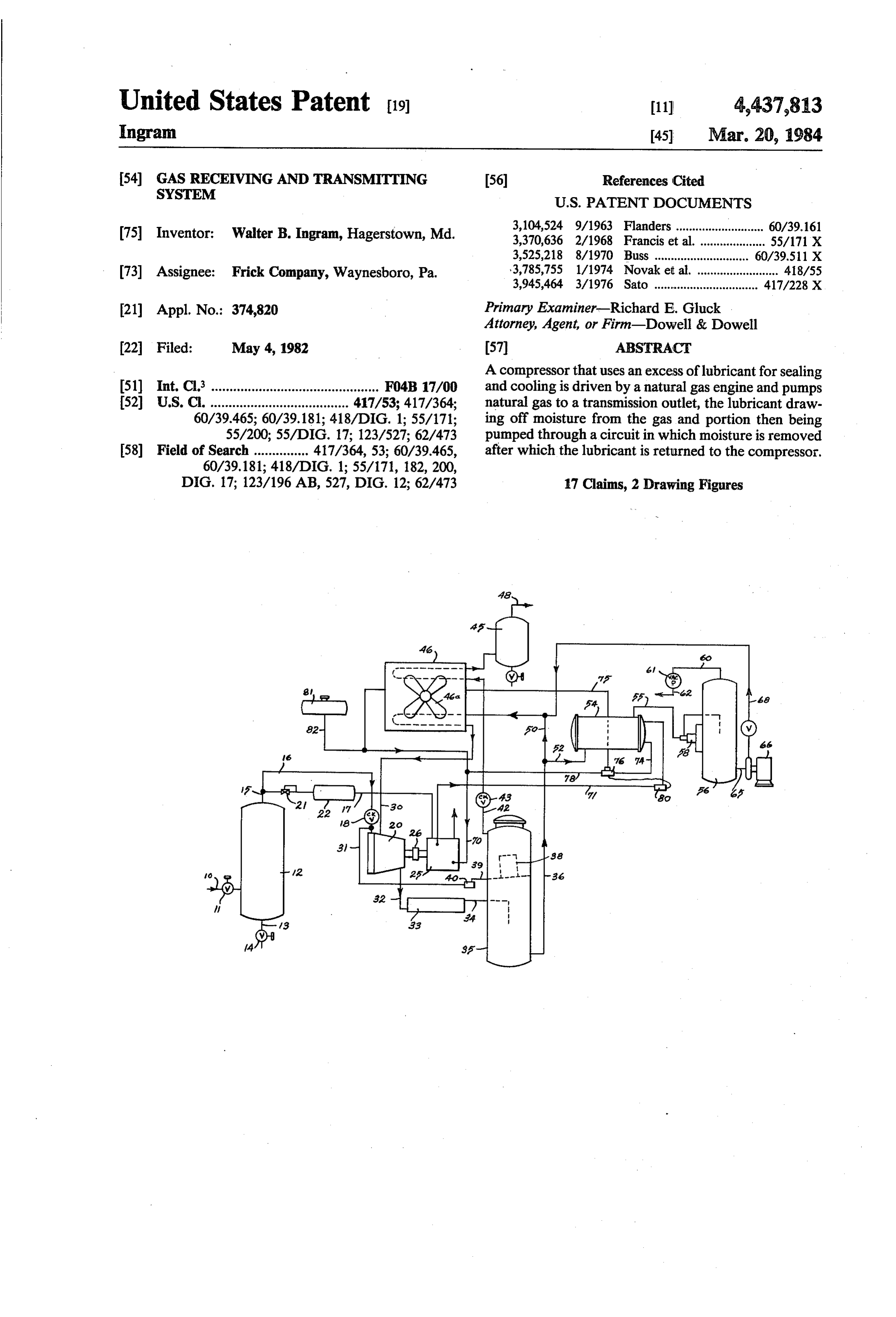
United States Patent (19) 11 4,437,813 Ingram 45 Mar. 20, 1984 (54) GAS RECEIVING AND TRANSMITTING (56) References Cited
SYSTEM
(75) Inventor: Walter B. Ingram, Hagerstown, Md. 3,104,524 9/1963 Flanders ........................... 60/39.161
3,525,218 8/1970 Buss ................. 60/39.511 X (73) Assignee: Frick Company, Waynesboro, Pa. 3,785,755 1/1974 Novak et al. ......................... 418/55 3,945,464 3/1976 Sato ................................ 417/228 X 21) Appl. No.: 374,820 Primary Examiner-Richard E. Gluck Attorney, Agent, or Firm-Dowell & Dowell 22 Filed: May 4, 1982 57 ABSTRACT
A compressor that uses an excess of lubricant for sealing (51) Int. Cl. .............................................. F04B 17/00 and cooling is driven by a natural gas engine and pumps (52) U.S. C. ...................................... 417/53; 417/364; natural gas to a transmission outlet, the lubricant draw 60/39.465; 60/39.181; 418/DIG. 1; 55/171; ing off moisture from the gas and portion then being 55/200; 55/DIG. 17; 123/527; 62/473 pumped through a circuit in which moisture is removed 58) Field of Search ............... 417/364, 53; 60/39.465, after which the lubricant is returned to the compressor.
DIG. 17; 123/196 AB, 527, DIG. 12; 62/473 17 Claims, 2 Drawing Figures
Page 2
Drawing sheet — no readable text.
Page 3
being diverted in heat exchange relation with coolant
GAS RECEIVING ANDTRANSMITTING SYSTEM from the engine and then placed under reduced pressure in order to remove the moisture, the moisture free oil
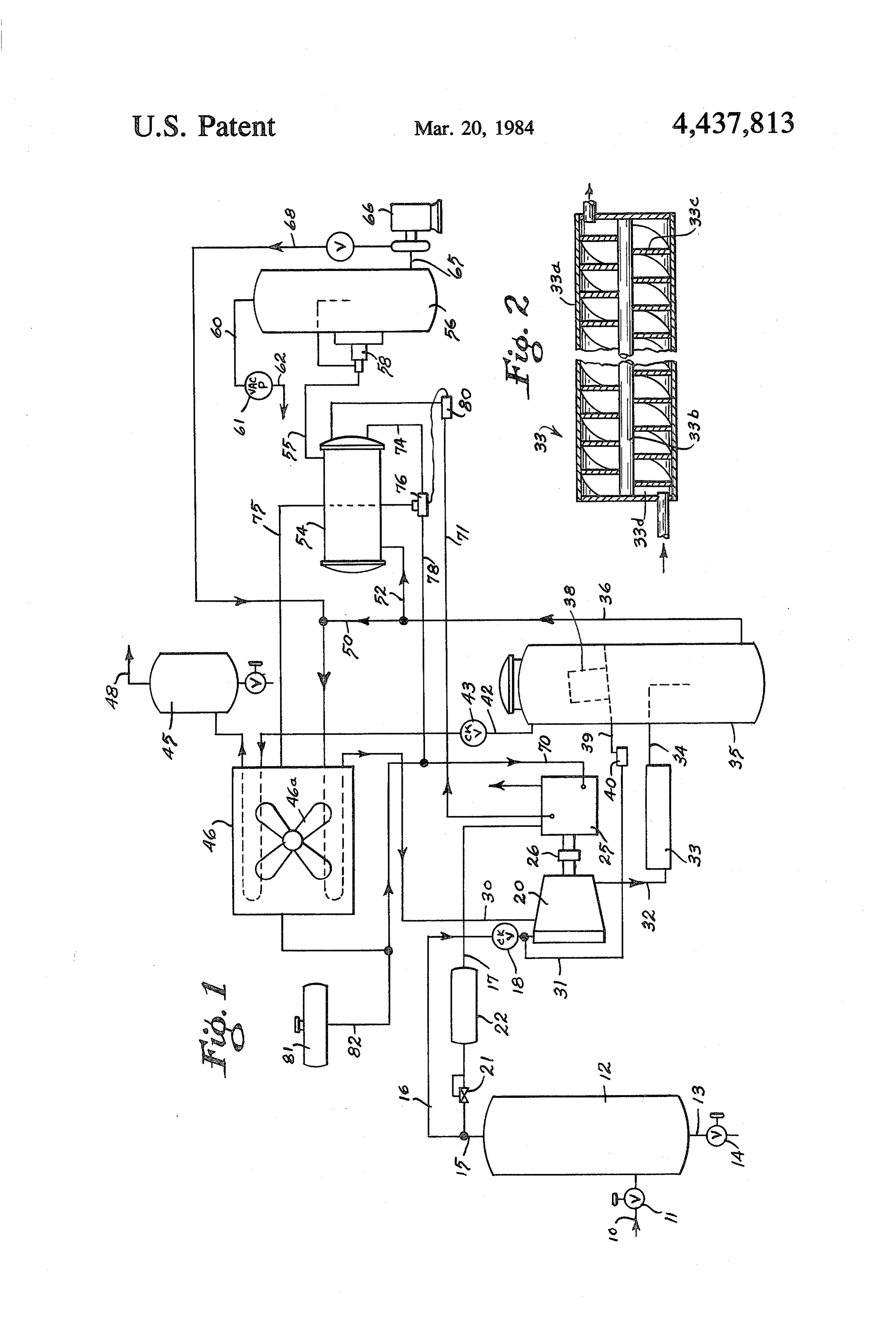
BACKGROUND OF THE INVENTION then being recirculated back to the compressor. This invention relates to the gathering or receiving 5 BRIEF DESCRIPTION OF THE DRAWING and pumping of natural gas in its raw state from wells and from sources fed by wells to a transmission line or FIG. 1 is a schematic layout of a system embodying other point of use. the invention.
Heretofore the pumping or compressing has ordinar 10 FIG. 2 is an enlarged section of the swirl tube. ily been done by reciprocating compressors due to the DESCRIPTION OF THE PREFERRED problem of moisture and other contaminants in the raw EMBODIMENT gas. The use of compressors that employ an excess of lubricant for sealing and cooling has apparently not With further reference to the drawings a supply pipe been feasible because of the problem of the moisture 15 10 having gate valve 11 feeds natural or raw gas into contaminating the lubricant. Thus various advantages separator 12. The gas is obtained from a well or other inherent in the use of a rotary compressor of the oil source and ordinarily is at a pressure of from two to injection type have not been possible in the pumping of fifteen pounds per square inch gauge. Raw gas com raw gas due to the contamination problem. monly has contaminants such as moisture and may in
clude droplets of water and hydrocarbons. In the sepa rator 12 such liquid contaminants are collected and may
The present invention relates to the pumping of fluids be drained from time to time through outlet 13 having particularly natural gas in which the gas provides the valve 14.
energy for the compressor and in which moisture is At the top of the separator 12 there is an outlet pipe removed from the oil continuously, and also from the 15 having a primary conduit 16 and a secondary branch
17. Conduit 16 has a one-way valve 18 to the inlet of
Compressors that employ an excess of lubricant for andBranch line 17 includes a pressure regulating valve 21 sealing and cooling are known in the art. These may gine 25 underdamper pulsation control 22 to an internal combustion en of a conventional gas engine include the screw type as referred to generally in the 30 governor system, not shown.
patent to Bulkley U.S. Pat. No. 3,856,493, the sliding pressor 20 through conventionalEngine 25 drives com coupling 26.
vane type as in the Sato U.S. Pat. No. 3,945,464, and the The compressor receives lubricant through inlet Nash-Hytor type as disclosed in the U.S. Pat. to pipes 30 and 31 and discharges gas under pressure hav Lowther No. 3,994,074. In Lowther, sulphuric acid is ing some lubricant entrained therewith through outlet used to remove water from a gas stream, the sulphuric pipe 32. Pipe
32 is connected to swirl tube 33 which acid being regenerated by an electrolytic process. An tends to throw the lubricant and water outwardly to other U.S. patent illustrative of the art is Novak et al. promote mixing thereof,
No. 3,785,755. the gas thus tending to separate The above patents also disclose various means of from the oil and water in the tube. From the tube an separating the oil from other components of the com 40 outlet pipe 34 discharges into oil separator 35. The swirl tube 33 is illustrated in more detail in FIG.
pressor discharge stream in order that the oil may be in satisfactory condition for recirculation through the 2. It includes an outer shell 33a, a center mandrel or compressor. shell 33b and a plurality of spaced fins 33c which are Wymer U.S. Pat. No. 4,279,628 discloses the use of wrapped on edge in a helical manner between the man triethylene glycol for mixing with water in a gas stream 45 drel and the outer shell, thereby providing separated and subsequent separation of the water by centrifugal flow channels 33d through the tube. The proportions of action. the tube may vary depending upon the size of the sys Brown U.S. Pat. No. 3,234,879 discloses a vacuum tem. An example is a tube approximately 50' (127 cm) pump which utilizes a single screw submerged in water in length and having a diameter of 6' (15.2 cm) and 12 with the vortex action producing vacuum. Lubricants 50 fins. The arrangement causes continuous rotation of the are not involved and water in the gas is separated by flowing gaseous materials between the outer shell and gravity. Brown also discloses pumping natural gas and inner mandrel.
using a portion of it as fuel for the engine that drives the The lubricant is preferably a synthetic oil, well pump. known in the art, which is miscible with water in order The use of turbines for pumping natural gas in which 55 that moisture may be more effectively removed from a portion is used as fuel is disclosed in various patents the gas. However, a conventional mineral oil lubricant including U.S. Pat. Nos. Flanders 3,104,524, Fono may be used due to the fact that the means for separat 3,107,482, Buss 3,525,218, and Fomichev 4,273,508. ing water from oil, to be described later, is effective SUMMARY OF THE INVENTION with either type of oil. A preferred lubricant for exam 60 ple is polyglycol based. This lubricant is not miscible in
The invention includes a compressor that uses an hydrocarbons so that any hydrocarbon liquids that are excess of lubricant for sealing and cooling and that is present will separate and float on the surface in the arranged to pump a fluid, a portion of which powers the separator 35. Water on the other hand is miscible in the engine that drives the compressor, the compressed gas lubricant and will go into solution. Since the lubricant and the compressed fluid with the lubricant being dis 65 has affinity for water it will tend to dry the gas. charged into a separator from which the gas is transmit Within the oil separator. 35 the relatively dense oil ted to a point of use, the mixed oil and moisture being and entrained water collects in its lower portion for recirculated back to the compressor, a portion thereof discharge through an outlet pipe 36. A minor portion of
Page 4
the oil in vaporous or lighter form is drawn into a co cially in swirl tube 33. The compressed and relative alescent filter element 38 located in the upper portion of moisture free gas is discharged through line 42 through the oil separator housing 35 and drains to outlet conduit heat exchanger 46 and line 48. Oil vapors which collect 39 and trap 40 to return line 31 to the compressor. in filter element 38 drain into line 39 for return to the The gas in the oil separator discharges through line compressor. The oil with water mixed therein passes 42 having a one-way valve 43 therein and into final through lines 36 and 50 to heat exchanger 46 and is separator 45 after passing through air cooled heat ex returned to the compressor by line 30. Since a certain changer 46. The gas discharging from final separator 45 amount of moisture in the oil is desirable or tolerable for through conduit 48 has been further reduced in mois compressor operation, only a portion of the oil mixture ture content to the extent that water, initially carried 10 from the oil separator 35 is diverted for removal of the with the gas, has mixed with the oil and been removed. moisture. This diverted oil water mixture is passed The oil and water mixture leaving the oil separator through line 52 through heater 54 and line 55 into the oil through pipe 36 has a major portion, which may be dehydrator 56. In the dehydrator the pressure is low approximately 90%, returned to the compressor via line ered sufficiently to vaporize moisture from the oil by 50 which passes through the air cooled heat exchanger 15 vacuum pump 61 which draws the water vapor out of 46 and to inlet pipe 30 to the compressor. the dehydrator 56. The oil in the lower portion of the A branch line 52 from line 36 diverts a portion of the dehydrator is withdrawn by pump 66 which is sized and oil and water, say about 10%, into an oil heater 54 from operated at a rate to divert the predetermined propor which it is discharged to line 55 into oil dehydrator 56, tion of the oil and water mixture from line 36. The pump the level in which is controlled by conventional means 20 causes the moisture free oil to flow through line 68 and such as float control 58. The oil dehydrator is con back to line 30.
nected at the top to line 60 to a vacuum pump 61 which The compressor is driven by engine 25 powered by applies approximately 25 inches of mercury vacuum gas running through lines 15 and 17. Coolant from the within the oil dehydrator thereby causing the water in engine is supplied through line 71 to heater 54, the re the oil to boil off and be discharged through outlet 62. 25 turn flow being controlled by valve 76 and sensor 80 to The moisture free oil is drawn through pipe 65 by pump maintain a desired temperature of coolant. 66 and is delivered by conduit 68 to the return line 30 I claim:
back to the compressor 20. 1. A system for receiving relatively high moisture The engine 25 has a cooling water system with inlet content raw gas from a location and pumping it in a 70 and discharge 71 to the oil heater 54 in order to heat 30 relatively dry condition to an outlet, comprising an oil the oil by heat exchange for purposes described. From injection type rotary compressor, an internal combus the oil heater the cooled water exits into line 74 for tion engine connected to drive said compressor, first return to the engine through line 75 and line 70, line 70 pipe means for carrying said raw gas to the inlet of said passing through air cooled heat exchanger 46. Valve 76 compressor, second pipe means for carrying raw gas to between lines 74 and 75 may divert varying amounts of 35 said engine, third pipe means for carrying oil to said water to line 78 back to line 70, said valve being con compressor, fourth pipe means leading from said com trolled by temperature responsive element 80 in line 71 pressor to a separator housing, means in said fourth pipe in order that the temperature in the oil heater 54 may be means for intermingling the fluids discharged from said maintained at a proper level. compressor, means in said separator housing for sepa The proportion of the oil and water mixture that is 40 rating the gas from the oil and water mixture, means for diverted through line 52 is governed primarily by the discharging dry gas from the upper portion of said sepa capacity and operation of pump 66. It has been found rator housing, discharge means from the lower portion that a diversion of approximately 10% with removal of of said housing for the mixture of oil and water, means water therefrom is sufficient to maintain the quality of for returning a predetermined major portion of said oil the oil but this proportion may be varied depending 45 and water mixture to the third pipe means to said com upon desired conditions by means well known in the pressor, means for diverting the remainder of said oil art. and water mixture, heat exchange means between said Water makeup and expansion to line 70 is provided means for diverting the remainder and said engine by tank 81 connected by line 82 to line 70. thereby raising the temperature of said diverted remain At the start-up of operation the speed of the engine 25 50 der of said oil and water mixture, a dehydrator housing, is set to a rate to accommodate the available gas flow, means carrying said diverted remainder to said dehy such rate being controlled by the conventional gover drator housing, pump means for drawing liquid from nor system. the lower portion of said dehydrator housing, means Similarly, the rate of operation of the air cooling fan connected to the upper portion of said dehydrator hous 46a for the heat exchanger 46, the pump 66 and the 55 ing for creating a vacuum therein whereby water vapor vacuum pump 61 are set at appropriate rates and inter is removed from the oil and drawn off from said dehy locked for operation during operation of the engine 25. drator housing, and means for returning the water-free Thus for a fixed gas flow rate the internal control of the oil from said pump means of said dehydrator housing to system is automatic. Automatic override of the engine said third pipe means to said compressor. speed, within fixed limits, may be provided when the 2. A system for receiving relatively high moisture amount of gas supply is variable. Appropriately safety fluid from a location and pumping it in a relatively dry relief and shutdown elements, well known in the art, condition to an outlet, comprising a lubricant sealed may also be provided. compressor, first pipe means for carrying said fluid to In operation, as applied to a flow of natural raw gas, the inlet of said compressor, second pipe means for the gas from line 10 and initial separator 12 passes 65 carrying lubricant to said compressor, third pipe means through lines 15 and 16 into compressor 20 from which from the outlet of said compressor to lubricant separa it flows together with oil from line 30 into oil separator tor means, said separator means separating the fluid 35, the oil having mixed with moisture in the gas, espe from the lubricant and water mixture, first discharge
Page 5
means from said lubricant separator means for said fluid, 11. The invention of claim 7, and means for bypassing second discharge means from said lubricant separator a portion of said coolant around said further cooling means for the mixture of lubricant and water, means for means in response to the temperature of said coolant returning a portion of said lubricant and water mixture sensed at said heater means, and means for sensing the to the second pipe means to said compressor, means for temperature of said coolant at said heater means. diverting the remainder of said lubricant and water 12. The invention of claim 11, in which the tempera mixture to lubricant dehydrator means, pump means for ture sensing means senses the temperature of the cool drawing lubricant from said lubricant dehydrator ant entering said heater means. means, said lubricant dehydrator means having means 13. The method of collecting and transmitting natural for lowering the pressure and for removing water vapor 10 gas flow having significant moisture present, compris from the lubricant, and means for returning the rela of ing using a portion of said gas flow to power an engine the type that evolves heat, using the engine to drive tively water-free lubricant from said pump means to the a compressor second pipe means to said compressor. that uses a surplus of lubricant for sealing and cooling, compressing the remainder of said gas flow 3. The invention of claim 2, and heat evolving power 15 in said compressor, injecting means driving said compressor, and heater means for pressor, intimately mixing saida lubricant lubricant into said com raising the temperature of said diverted lubricant and order that the lubricant will mix with thewith the gas in water in the water mixture.
4. The invention of claim 3 in which a coolant circu gas, separating the lubricant and water mixture from the gas, discharging the compressed relatively moisture lates between said power means and said heater means 20 free gas, returning a predetermined portion of the lubri for raising the temperature of said mixture. cant and water mixture to the compressor, diverting the 5. The invention of claim 3, in which said heat evolv remainder of the mixture in heat exchange relations ing power means is powered by a portion of said rela with the engine to elevate the temperature of the mix tively high moisture fluid. ture, lowering the pressure of the mixture sufficiently to 6. The invention of claim 2, in which said pump 25 vaporize the water, withdrawing the water vapor, and means controls the proportionate amount of the lubri pumping the remaining lubricant back to the compres cant and water mixture that is diverted. SO.
7. The invention of claim 4, in which means is pro 14. The method of claim 13 in which the lubricant is vided for cooling the lubricant returning to said com the type that is relatively miscible with water but not pressor and means for further cooling said coolant after 30 miscible with hydrocarbons.
it exchanges heat with said diverted remainder of said 15. The method of claim 13 in which the engine has a lubricant. coolant flowing in a cooling system and the coolant 8. The invention of claim 2, said lubricant separator flows in heat exchange relation with the diverted mix having means for trapping vaporous lubricant, and 35 ture of lubricant and water, and sensing the temperature means for collecting and returning said trapped lubri of the coolant before it passes in heat exchange relation cant to said compressor. with the diverted mixture, and further cooling a portion 9. The invention of claim 2, said third pipe means of the coolant after said heat exchange relation, such having tube means for intermingling the fluid and lubri portion being determined in response to the said sensed temperature of the coolant.
cant discharged from said compressor. 40 16. The method of claim 13 in which the lubricant is 10. The invention of claim 9, said tube means having pumped back to the compressor at a predetermined rate internal flow directing means to cause helical move to control the portion of the mixture that is diverted. ment of said fluid and lubricant thereby producing cen 17. The method of claim 13 in which the lubricant is trifugal forces tending to cause said lubricant and the intimately mixed with the gas after compression by water in the fluid to flow outwardly toward the inner 45 subjecting them to centrifugal force so that the lubri periphery of said tube means thereby promoting mixing cant and water will mix more intimately. of the lubricant and the water. k k k
Provenance
- Collection
- Cited prior art
- Original PDF
- patentimages.storage.googleapis.com →
- Filed
- 1982-05-04
- Pages
- 5
- Method
- pdftotext (the PDF's own text layer) + pdftoppm 300dpi page scans
- Source
- Google Patents bibliographic record
- Granted
- 1984-03-20
- Inventors
- Walter B. Ingram; Frick Co Inc
- Transcribed from
- patentimages.storage.googleapis.com →