patent · US5027758
Fuel system for crankcase scavenged two cycle spark ignition engines
2 July 1991
Page 1 — bibliographic record
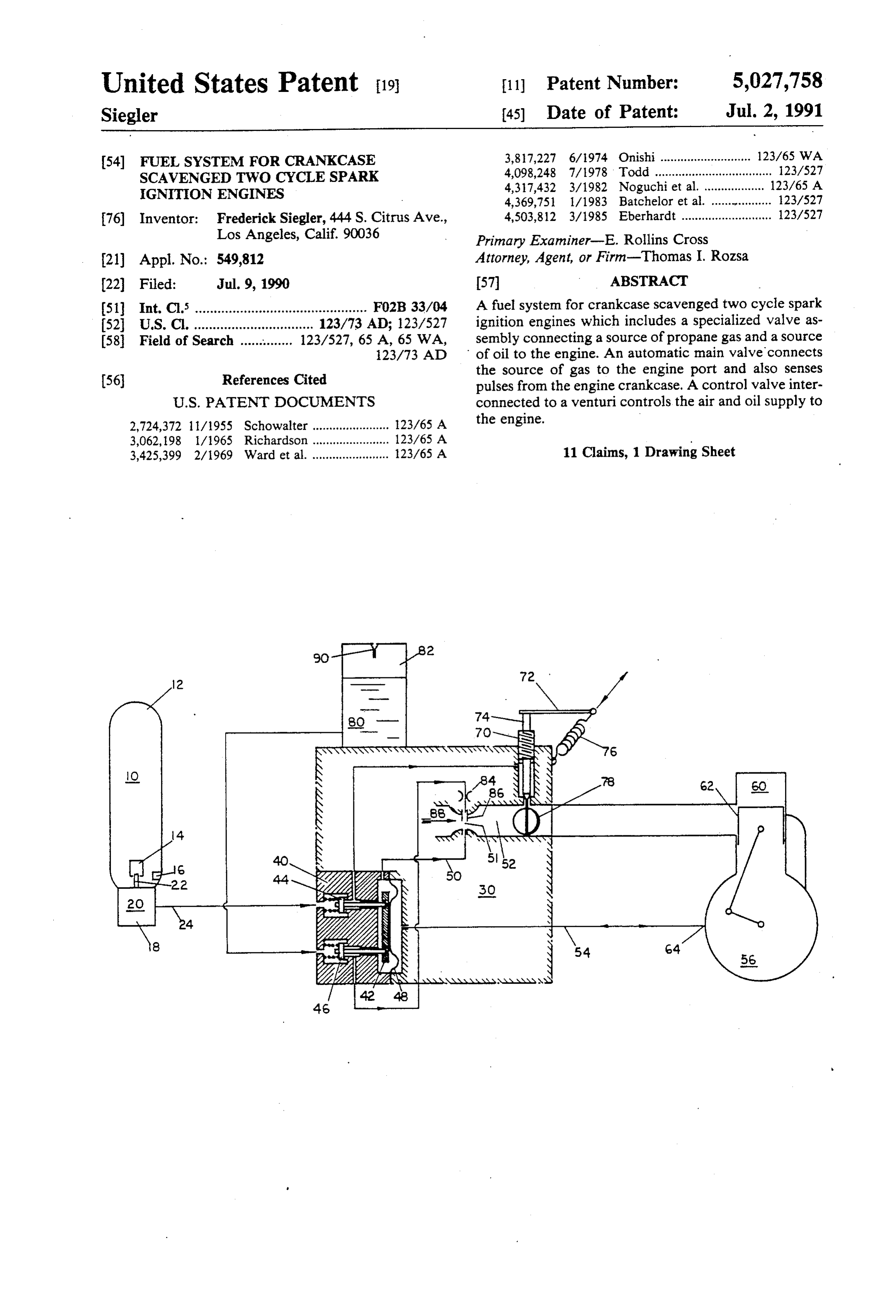
United States Patent (19) 11 Patent Number: 5,027,758 Siegler 45) Date of Patent: Jul. 2, 1991 (54) FUEL SYSTEM FOR CRANKCASE 3,817,227 6/1974 Onishi ........................... 123/65 WA SCAVENGED TWO CYCLE SPARK 4,098,248 7/1978 Todd ................................... 123/527 IGNITION ENGINES 4,317,432 3/1982 Noguchi et al. .................. 123/65 A
76) Inventor: Frederick Siegler, 444 S. Citrus Ave., 4,503,812 3/1985 Eberhardt ........................... 123/527 Los Angeles, Calif. 90036 Primary Examiner-E. Rollins Cross (21) Appl. No.: 549,812 Attorney, Agent, or Firm-Thomas I. Rozsa 22 Filed: Jul. 9, 1990 57 ABSTRACT (51) Int. Cl. .............................................. FO2B33/04 A fuel system for crankcase scavenged two cycle spark (52) U.S.C. ................................ 123/73 AD; 123/527 ignition engines which includes a specialized valve as (58 Field of Search ....... . . . . . . . 123/527, 65 A, 65 WA, sembly connecting a source of propane gas and a source 23/73 AD of oil to the engine. An automatic main valve connects
References Cited the source of gas to the engine port and also senses (56) pulses from the engine crankcase. A control valve inter
2,724,372 11/1955 Schowalter ....................... 23/65 A the engine.
3,425,399 2/1969 Ward et al. ....................... 123/65 A 11 Claims, 1 Drawing Sheet
Page 2
Drawing sheet — no readable text.
Page 3
the engine components. Because of the two cycle oper
FUEL SYSTEM FOR CRANKCASE SCAVENGED ating principle, part of the incoming mixture is dis
TWO CYCLE SPARK IGNITION ENGINES charged through the exhaust port as part of the scav enging process, leaving unburned hydrocarbons in the
BACKGROUND OF THE INVENTION 5 exhaust. Furthermore, much of the lubricating oil burns 1. Field of the Invention and contributes to smoke and unfavorable exhaust emis The present invention relates to the fuel system of sionTheandfuelodor.
Small two cycle crankcase scavenged spark ignition engine and system consists of a fuel tank attached to the engines typically used for yard blowers and trimmers 10 typically a connected membrane to a gasoline carburetor which is carburetor as manufactured by and similar equipment, to operate on LPG (liquified petroleum gas) such as propane, to eliminate air pollu Walbro Co., Tillotson and several domestic and foreign tion, fuel mixing and providing single step starting, manufacturers. This is a precision device consisting at making these engines more user friendly. The present least of thirty components and several minute holes. invention further relates to the substitution of a novel 15 The engine crankcase pressure pulses are used to oper fuel system and carburetor assembly to replace the gas ate a small pulse pump to feed a metering chamber oline fuel tank and gas line conventionally used with which dispenses fuel into the carburetor venturi as a such two cycle crankcase scavenged spark ignition function of air flow and throttle position. Providing engines. starting fuel at cranking speed and controlling fuel at 2. Description of the Prior Art peak power is a considerable task which explains the A conventional two stroke engine is provided with a 20 need for complexity and required precision of this type scavenging fan. At the start of the first stroke, the piston of carburetor. As a consequence, the cost of the carbu is in its highest position. When the compressed petrol retor is high and is a considerable part of the total en and-air over the piston is ignited, the latter is thrust gine cost. Furthermore, it is one of the weak points of downwards and, in so doing, releases the exhaust port. engine reliability and cause of hard starting. Starting of The burned gases in the cylinder, which are still under 25 these engines is accomplished with a rope starter which high pressure, can thus escape through this port. When has a spring rewind pulley and a ratchet that engages the piston descends further, its upper edge releases the the crankshaft through pawls. When the engine starts, inlet port, which admits fresh petrol-and-air mixtures, the pawls disengage due to the centrifugal force acting delivered by a fan, into the cylinder, so that the remain 30 on them. The starting procedure involves several steps ing burned gases are flushed out. When the piston rises which must be performed in sequence. If it is done again on the second stroke, all the ports are closed off incorrectly, the engine will not start which is the most for a time, and during this period the petrol-and-air frequent consumer complaint. The typical starting se mixture is compressed, so that a fresh cycle can com quence requires: to turn on the ignition, to close the eCe.
The crankcase-scavenged two-stroke engine has no 35 on choke, set the throttle to a starting position, briskly pull scavenging fan. Instead, the crankcase is hermetically openthethestarter until the first pop is heard, readjust or sealed, so that it can function as a pump in conjunction engine starts, warmbriskly choke, up the pull on the starter until the engine before loading. Start with the piston. When the piston ascends, a partial vac ing a warm engine has its own uum is produced in the crankcase, until the lower edge lock because of heat soak. Thereproblems such as vapor are also variations on of the piston releases the inlet port and thus opens the the above procedure such as hand priming prior to way to the fresh petrol-and-air mixture into the crank case. When the piston descends, the mixture in the starting.
crankcase is compressed a little so that, as soon as the fuelTherefore, there is a significant need for an improved system which operates on cleaner burning fuel such top of the piston releases the transfer port and overflow as duct which connects the crankcase to the cylinder, it 45 liquid propane and which eliminates or significantly can enter the cylinder. Meanwhile, what happens above reduces the problems addressed above. the piston is the same as in the fan scavenged engine. SUMMARY OF THE INVENTION The lubricating oil is mixed with the petrol or is, alter The present invention relates to an improved fuel natively, supplied to the points of lubrication dropwise by small lubricating oil pumps. The oil which enters the 50 system and assembly which replaces the conventional crankcase is liable to be carried through the overflow engines. fuel system in crankcase scavenged two cycle gasoline duct and transfer port into the cylinder, where it passes The present invention relates to a novel approach to through the exhaust port and into the exhaust system. resolve air pollution problems, to eliminate fuel mixture The two cycle crankcase scavenged spark ignition preparation, engines known as two cycle SI engines are predomi 55 these enginestouser-friendly simplify the starting procedure, to make and more acceptable for the nantly used to power hand tools made for the garden industry and to a lesser extent for the construction and consumer market with particular attention paid to the building industry. The power rating of these engines are environment.
from a few tenth of a horsepower to several horse The fuel system is retrofit with minor external modifi power. The two cycle SI engines dominate this field cations to the engine structure, such as replacing the because they provide mobility at a light weight and a gasoline fuel tank with an adapter to support an LPG reasonable initial cost. propane bottle.
The fuel for these engines is a mixture of gasoline and To resolve the exhaust emission problem, LPG pro lubricating oil in a predetermined ratio which must be pane was selected which is commercially available from mixed by the user. This is an unpleasant chore for the 65 any hardware store in 14.1 or 16.4 oz. capacities. consumer, often resulting in improper mixture ratio. Propane is used as a fuel on large engines such as fork The fuel mixture provides fuel for the combustion pro the lifts so that they can operate indoors without poisoning cess and the oil contained in it provides lubrication for atmosphere. Large engines are typically for cycle SI
Page 4
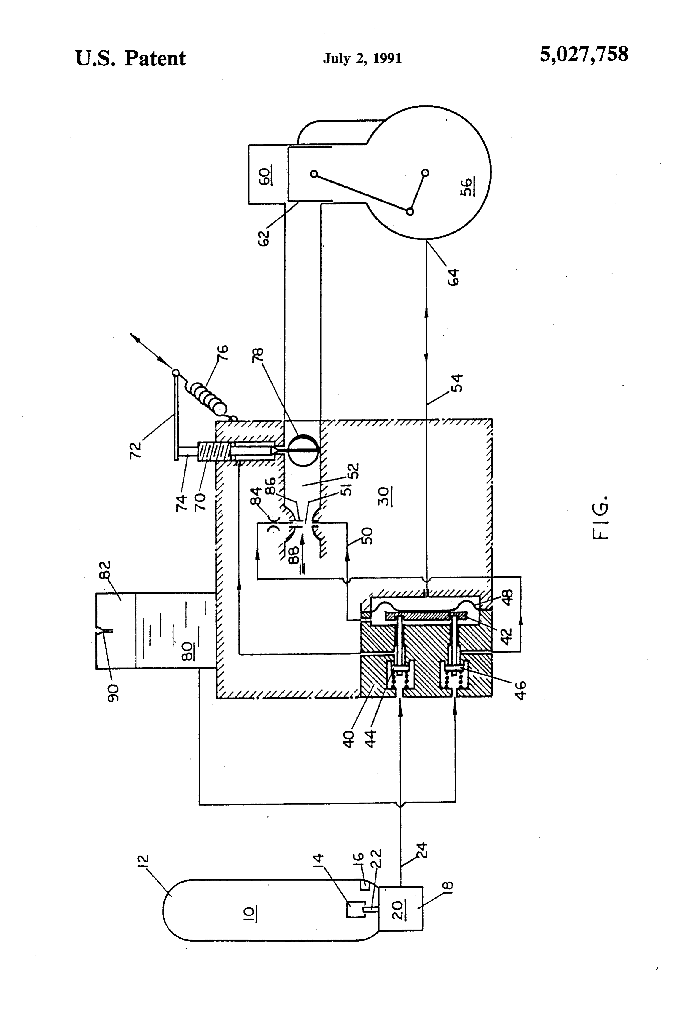
engines which have a separate fuel system and a sepa gas 10 to enter the regulator valve 20 which reduces the rate lubrication system. bottle pressure to system pressure and maintains this It has been discovered, according to the present in pressure regardless of flow.
vention, that if liquid propane is used instead of gasoline A conduit or gas line 24 with proper fittings to con to burn in crankcase-scavenged two cycle engines, then nect the pressure reducing and regulating valve with the engine will burn much cleaner. the carburetor body 30. The carburetor 30 may be con It has further been discovered, according to the pres nected to the engine cylinder 60 with a thin gasket to ent invention, that if the carburetor is modified to con assure maximum heat transfer to the carburetor 30. prise specialized valves and an oil reservoir to effi An automatic main valve 40 is down-stream from the ciently combine the propane fuel and oil, then the user 10 pressure regulating valve 20 and it is housed in the will not need to separately mix the fuel and oil. carburetor body 30 which is attached directly to the It is therefore an object of the present invention to intake port 62 of the cylinder 60 and in connection with provide an efficient and clean burning crankcase scav the pulse port 64 of the crankcase 56. The automatic enged two cycle engine. main valve 40 is a double valve with a single actuator It is an additional object of the present invention to 15 42, normally closed by spring load for initial seating and provide such a crankcase scavenged two cycle engine by the gas system pressure and oil head. The main valve which is run by liquid propane gas and not gasoline. 40 has a gas valve 44 and an oil valve 46. The main It is a further object of the present invention to pro valve 40 prevents gas from entering the carburetor vide a crankcase scavenged two cycle engine which has when the engine is not running and when the LPG automatic valves and an oil supply reservoir which can 20 bottle is attached to the engine. It also prevents oil from be combined with the propane gas to provide an effi draining when the engine is stored. The automatic main cient system for feeding the oil and fuel to the crankcase valve 40 is normally closed by the system pressure and and cylinder of the two cycle engine without the re spring load. The automatic main valve 40 also has quirement for the user to separately mix the fuel and oil. means to sense the engine rotation to thereby open due Further novel features and other objects of the pres 25 to crankcase pulse or venturi vacuum or the combina ent invention will become apparent from the following tion of the two. When the rope starter is activated and detailed description, discussion and the appended claim, the engine is turned over, vacuum 50 is generated in the taken in conjunction with the drawings. carburetor venture 52 and pressure pulses 54 in the
BRIEF DESCRIPTION OF THE DRAWINGS
crankcase 56. A diaphragm actuator 48 senses the pres 30 sure differential between the carburetor venture 52 and
Referring particularly to the drawings for the pur the crankcase pulses 54 which, in turn, acts on the gas pose of illustration only and not limitation, there is valve 44 and cracks it open, permitting gas 10 to enter illustrated: carburetor 30. When the engine starts, the carburetor The FIGURE is a schematic diagram of the present. venture vacuum 50 becomes predominant and keeps the invention fuel system for crankcase scavenged two 35 main valve 40 open while the engine runs. When the cycle spark ignition engines. engine is stopped by cutting out the ignition, the main valve 40 automatically closes and prevents the gas 10 or
DETAILED DESCRIPTION OF THE oil 80 from entering the carburetor 30.
PREFERRED EMBODIMENT The control valve 70 is down-stream from the auto Although specific embodiments of the invention will matic main valve 40. This is a needle valve rotatably now be described with reference to the drawings, it seated in the carburetor body 30. Its function is to con should be understood that such embodiments are by trol the gas flow to the engine cylinder 60 by closing or way of example only and merely illustrative of but a opening. This is accomplished by a spring biased arm 72 small number of the many possible specific embodi attached to the control valve stern 74. The spring 76 ments which can represent applications of the principles 45 tends to close the valve 70 and is acting against a manual of the invention. Various changes and modifications control force typically generated by a finger trigger obvious to one skilled in the art to which the invention mechanism to open the valve 70 to increase speed. The pertains are deemed to be within the spirit, scope and preferred orientation of the needle valve is on center contemplation of the invention as further defined in the with the venture 50 and perpendicular to its axis. It can appended claims. 50 thereby control both air and gas flow. To the extension The FIGURE is a schematic diagram of the present of the small end of the needle valve, a butterfly valve 78 invention fuel system for crankcase scavenged two may be attached to control air/fuel ratio and also to cycle spark ignition engines. The source of fuel is liquid facilitate the mixing of air, gas and oil in the venturi propane gas 10 which is housed inside a liquid propane prior to entering the engine. Test engines operated satis gas bottle 12. By way of example, the liquid propanegas 55 factorily without the butterfly valve 78 where air/fuel bottle 12 may be a Standard 14.1 or 16.4 oz. LPG pro ratio was controlled by venturi throat size and control pane bottle with a standard threaded adapter, built-in valve opening.
check valve and pressure relief valve as per DOT Oil 80 is housed in an oil reservoir 82. Oil flow to the 39NRC 228/286. The built in check valve is illustrated engine is controlled by a properly sized orifice 84 which at 14 and the pressure relieve valve is illustrated at 16. is down-stream from an automatic main valve 40 and its A standard pressure reducing and regulating valve 20 oil valve 46. The differential pressure between the oil such as sold by the Coleman Co., is mounted to a metal reservoir 82 and the venturi vacuum 50 forces the oil 80 part of the engine such as the fan housing to support one into the venturi throat 51. The form of oil discharge can end 18 of the LPG propane bottle 12 and to warm the be controlled by the oil exit hole to the venturi. A pro propane gas with engine heat as it tends to cool when its 65 truding tube 86 into the air stream 88 provides atomiza pressure is reduced. When the LPG bottle 12 is attached tion of the oil 80. Elimination of the discharge tube 86 to the engine, its internal check valve 14 is opened by permits the oil 80 to ooze out of the hole and forced to the regulator valve prong 22 and permits the propane the engine port 62 on the venturi wall by the air motion.
Page 5
A proper compromise between these two limits can use, since the same may be modified in various particu minimize suspended oil in the air to leave the engine lars or relations without departing from the spirit or during the scavenging period. For lubrication, approxi scope of the claimed invention hereinabove shown and mately 7cc. oil is needed per 14.1 oz. propane. The oil described of which the apparatus is intended only for reservoir 82 must be transparent so that the oil level can 5 illustration ment and and for disclosure of an operative embodi not to show all of the various forms of modifi be observed. It may be attached to the carburetor or it may be remotely mounted depending from the installa cation in which the invention might be embodied or tion. The oil reservoir 82 is equipped with a rubber operated. The invention has been described in considerable check valve 90 permitting air to enter and preventing oil to spill. The gravity feed arrangement is the most 10 detail in order to comply with the patent laws by pro cost-effective and sufficient for string trimmer and viding full public disclosure of at least one of its forms. blower installation. This does not exclude a more so However, such detailed description is not intended in phisticated system such as an all position metering any way to limit the broad features or principles of the pump. The gravity fed oil supply 82 also may include invention, or the scope of patent monopoly to be means to automatically shut off when the engine control 15 granted.
is deactivated. This prevents oil from draining into the What is claimed is:
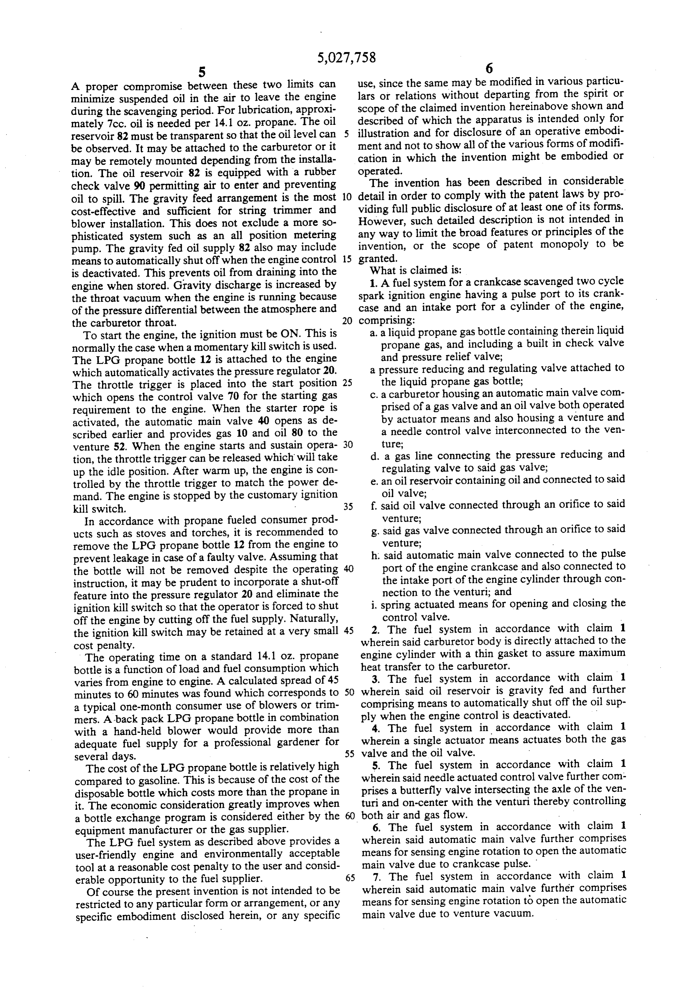
engine when stored. Gravity discharge is increased by spark 1. A fuel system for a crankcase scavenged two cycle the throat vacuum when the engine is running because ignition engine having a pulse port to its crank of the pressure differential between the atmosphere and case and an intake port for a cylinder of the engine, the carburetor throat. 20 comprising:
To start the engine, the ignition must be ON. This is a. a liquid propane gas bottle containing therein liquid normally the case when a momentary kill switch is used. propane gas, and including a built in check valve The LPG propane bottle 12 is attached to the engine and pressure relief valve; which automatically activates the pressure regulator 20. a pressure reducing and regulating valve attached to The throttle trigger is placed into the start position 25 the liquid propane gas bottle; which opens the control valve 70 for the starting gas c. a carburetor housing an automatic main valve com requirement to the engine. When the starter rope is prised of a gas valve and an oil valve both operated activated, the automatic main valve 40 opens as de by actuator means and also housing a venture and scribed earlier and provides gas 10 and oil 80 to the a needle control valve interconnected to the ven venture 52. When the engine starts and sustain opera 30 ture;
tion, the throttle trigger can be released which will take d. a gas line connecting the pressure reducing and up the idle position. After warm up, the engine is con regulating valve to said gas valve; trolled by the throttle trigger to match the power de e, an oil reservoir containing oil and connected to said mand. The engine is stopped by the customary ignition oil valve;
kill switch. 35 f, said oil valve connected through an orifice to said In accordance with propane fueled consumer prod venture;
ucts such as stoves and torches, it is recommended to g. said gas valve connected through an orifice to said remove the LPG propane bottle 12 from the engine to venture;
prevent leakage in case of a faulty valve. Assuming that h. said automatic main valve connected to the pulse the bottle will not be removed despite the operating 40 port of the engine crankcase and also connected to instruction, it may be prudent to incorporate a shut-off the intake port of the engine cylinder through con feature into the pressure regulator 20 and eliminate the nection to the venturi; and ignition kill switch so that the operator is forced to shut i. spring actuated means for opening and closing the off the engine by cutting off the fuel supply. Naturally, control valve.
the ignition kill switch may be retained at a very small 45 2. The fuel system in accordance with claim 1 cost penalty. wherein said carburetor body is directly attached to the The operating time on a standard 14.1 oz. propane engine cylinder with a thin gasket to assure maximum bottle is a function of load and fuel consumption which heat transfer to the carburetor.
varies from engine to engine. A calculated spread of 45 3. The fuel system in accordance with claim 1 minutes to 60 minutes was found which corresponds to 50 wherein said oil reservoir is gravity fed and further a typical one-month consumer use of blowers or trim comprising means to automatically shut off the oil sup mers. A back pack LPG propane bottle in combination ply when the engine control is deactivated. with a hand-held blower would provide more than 4. The fuel system in accordance with claim 1 adequate fuel supply for a professional gardener for wherein a single actuator means actuates both the gas several days. 55 valve and the oil valve.
The cost of the LPG propane bottle is relatively high 5. The fuel system in accordance with claim 1 compared to gasoline. This is because of the cost of the wherein said needle actuated control valve further com disposable bottle which costs more than the propane in prises a butterfly valve intersecting the axle of the ven it. The economic consideration greatly improves when turi and on-center with the venturi thereby controlling a bottle exchange program is considered either by the both air and gas flow.
equipment manufacturer or the gas supplier. 6. The fuel system in accordance with claim The LPG fuel system as described above provides a wherein said automatic main valve further comprises user-friendly engine and environmentally acceptable means for sensing engine rotation to open the automatic tool at a reasonable cost penalty to the user and consid main valve due to crankcase pulse.
erable opportunity to the fuel supplier. 65 7. The fuel system in accordance with claim 1 Of course the present invention is not intended to be wherein said automatic main valve further comprises restricted to any particular form or arrangement, or any means for sensing engine rotation to open the automatic specific embodiment disclosed herein, or any specific main valve due to venture vacuum.
Page 6
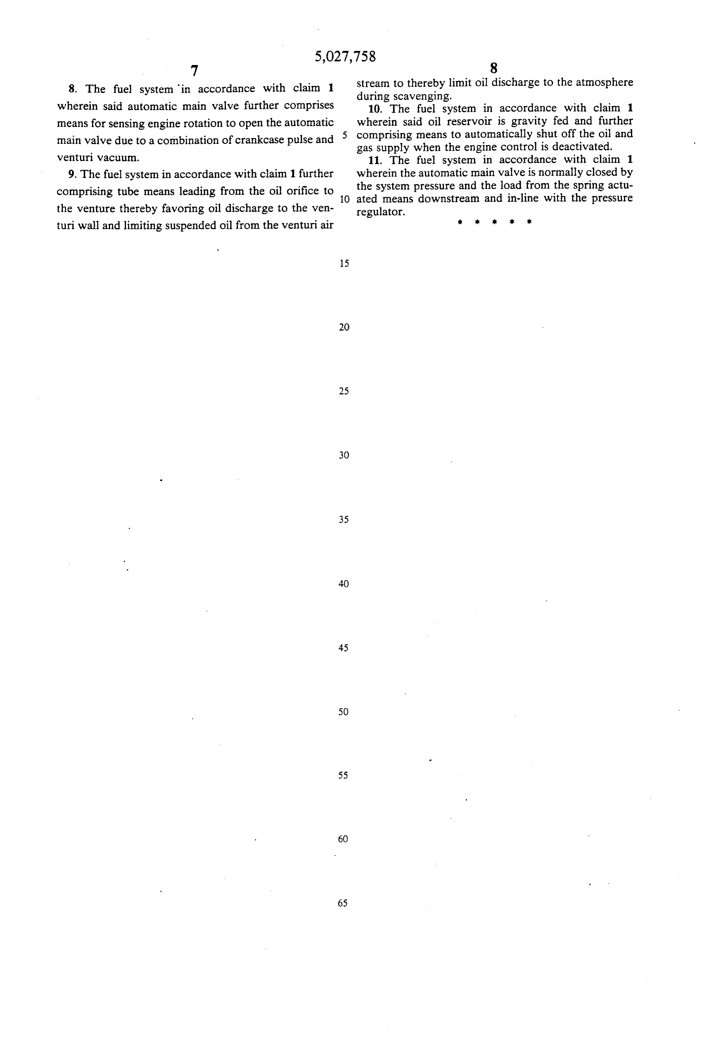
8. The fuel system in accordance with claim 1 stream to thereby limit oil discharge to the atmosphere during scavenging.
wherein said automatic main valve further comprises 10. The fuel system in accordance with claim 1 means for sensing engine rotation to open the automatic wherein said oil reservoir is gravity fed and further comprising means to automatically shut off the oil and main valve due to a combination of crankcase pulse and 5 gas supply when the engine control is deactivated. venturi vacuum. 11. The fuel system in accordance with claim 1 9. The fuel system in accordance with claim 1 further wherein the automatic main valve is normally closed by comprising tube means leading from the oil orifice to 10 the system pressure and the load from the spring actu ated means downstream and in-line with the pressure the venture thereby favoring oil discharge to the ven regulator.
turi wall and limiting suspended oil from the venturi air
Page 7
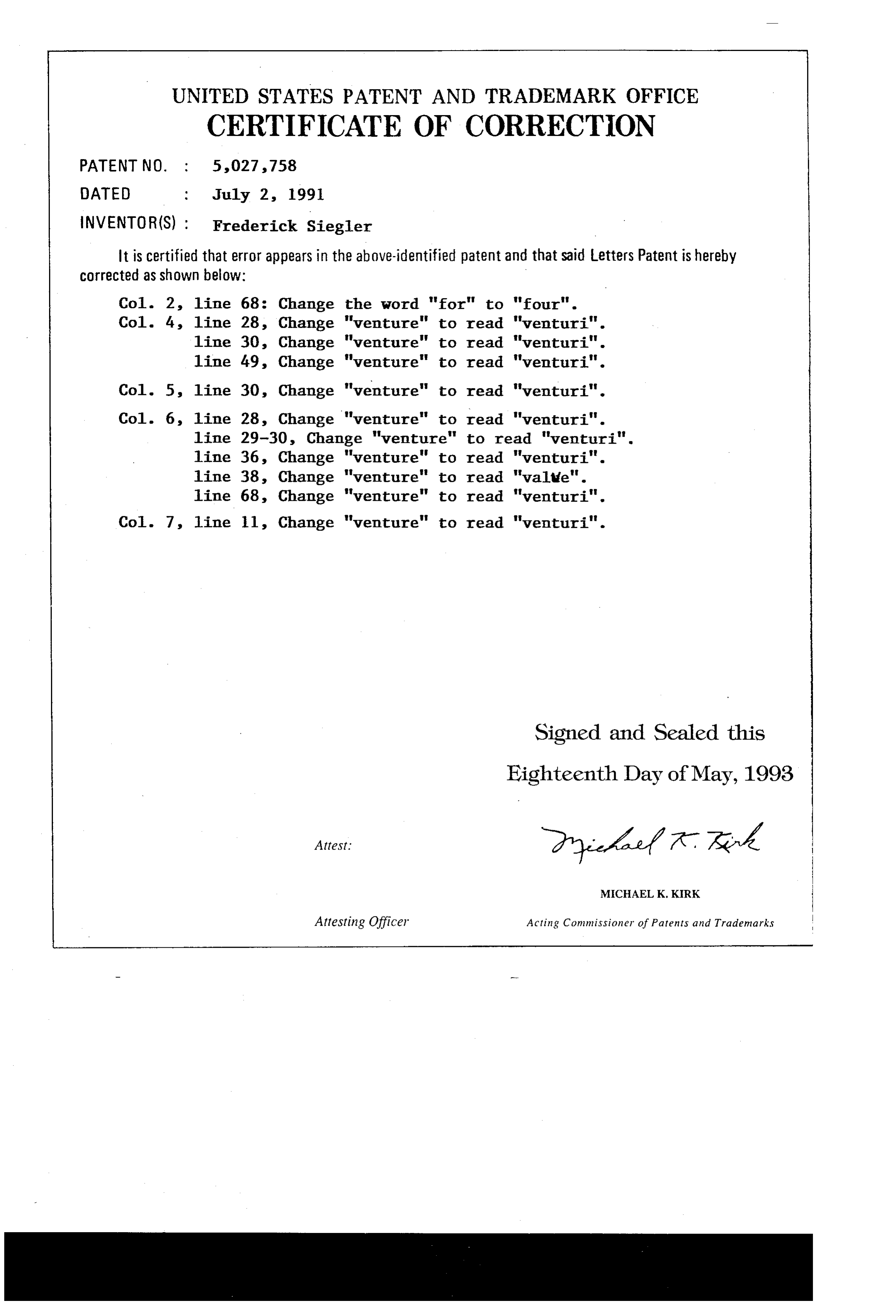
UNITED STATES PATENT AND TRADEMARK OFFICE
CERTIFICATE OF CORRECTION
INVENTOR(S) : Frederick Siegler
It is certified that error appears in the above-identified patent and that said Letters Patent is hereby Corrected as shown below:
Col. 2, line 68: Change the word "for" to "four". Col. 4, line 28, Change "venture" to read "venturi". line 30, Change "venture" to read "venturi". line 49, Change "venture" to read "venturi". Col. 5, line 30, Change "venture" to read "venturi". Col. 6, line 28, Change "venture" to read "venturi". line 29-30, Change "venture" to read "venturi". line 36, Change "venture" to read "venturi". line 38, Change "venture" to read "valle". line 68, Change "venture" to read "venturi". Col. 7, line ll, Change "venture" to read "venturi".
Signed and Sealed this
Eighteenth Day of May, 1993
MICHAEL K. KRK
Attesting Officer Acting Commissioner of Patents and Trademarks
Provenance
- Collection
- Cited prior art
- Original PDF
- patentimages.storage.googleapis.com →
- Filed
- 1990-07-09
- Pages
- 7
- Method
- pdftotext (the PDF's own text layer) + pdftoppm 300dpi page scans
- Source
- Google Patents bibliographic record
- Granted
- 1991-07-02
- Inventors
- Frederick Siegler
- Transcribed from
- patentimages.storage.googleapis.com →