patent · US4697553
Lubricating oil input system
6 October 1987
Page 1 — bibliographic record
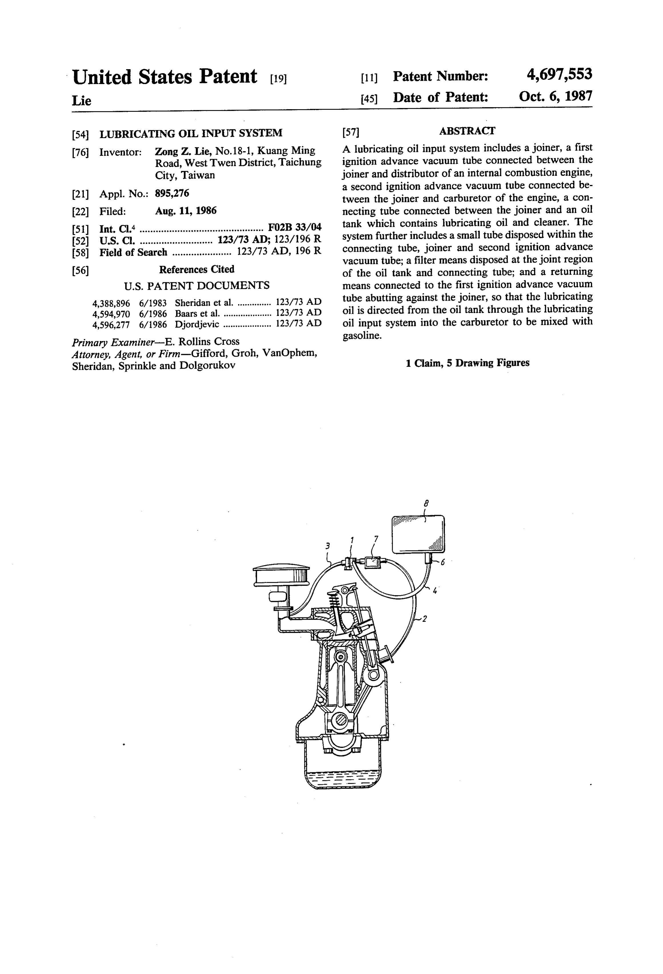
United States Patent (19) 11 Patent Number: 4,697,553 Lie 45) Date of Patent: Oct. 6, 1987 (54) LUBRICATING OIL INPUT SYSTEM 57 ABSTRACT 76 Inventor: Zong Z. Lie, No. 18-1, Kuang Ming A lubricating oil input system includes a joiner, a first Road, West Twen District, Taichung ignition advance vacuum tube connected between the City, Taiwan joiner and distributor of an internal combustion engine, (21) Appl. No.: 895,276 a second ignition advance vacuum tube connected be tween the joiner and carburetor of the engine, a con 22 Filed: Aug. 11, 1986 necting tube connected between the joiner and an oil 51) Int. Cl. .............................................. FO2B33/04 tank which contains lubricating oil and cleaner. The 52) U.S. Cl. .............. ... 123/73 AD; 123/196R system further includes a small tube disposed within the 58) Field of Search ...................... 123/73 AD, 196R connecting tube, joiner and second ignition advance vacuum tube; a filter means disposed at the joint region 56) References Cited of the oil tank and connecting tube; and a returning
4,388,896 6/1983 Sheridan et al. .............. 123/73 AD tube abutting against the joiner, so that the lubricating 4,594,970 6/1986 Baars et al. . ... 123/73 AD oil is directed from the oil tank through the lubricating 4,596,277 6/1986 Djordjevic .................... 123/73 AD oil input system into the carburetor to be mixed with Primary Examiner-E. Rollins Cross gasoline.
Attorney, Agent, or Firm-Gifford, Groh, VanOphem,
Sheridan, Sprinkle and Dolgorukov 1 Claim, 5 Drawing Figures
areera
Peka
Page 2
Drawing sheet — no readable text.
Page 3
Drawing sheet — no readable text.
Page 4
Drawing sheet — no readable text.
Page 5
Drawing sheet — no readable text.
Page 6
Drawing sheet — no readable text.
Page 7
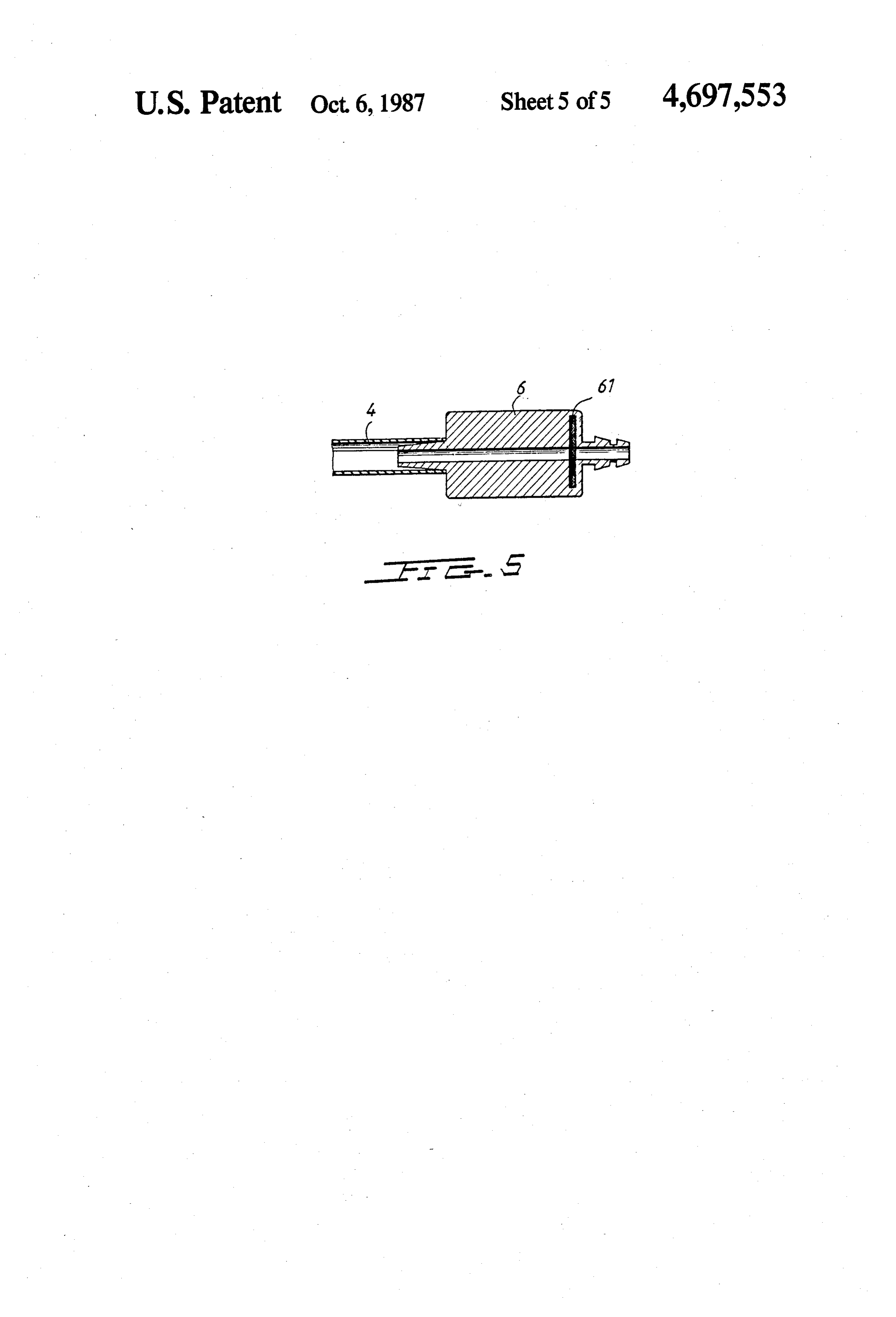
FIG. 5) disposed at the base of the oil tank (8) which on
LUBRICATING OIL NPUT SYSTEM the other end joins with the connecting tube (4). A filter medium (61) is disposed at the output side of the filter
BACKGROUND OF THE INVENTION means (6) to filter the lubricating oil. The returning 5 means (7) is disposed on the first ignition advance vac
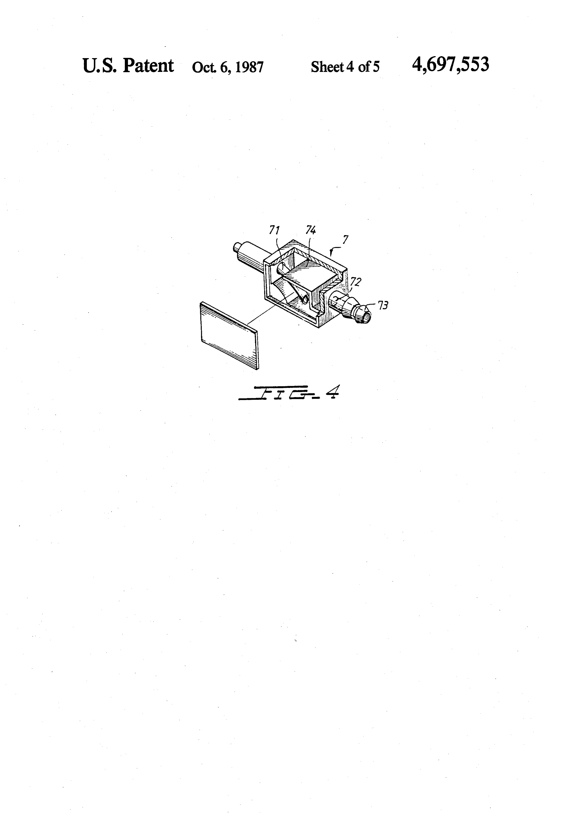
Gasoline must be mixed with lubricating oil and then uum tube (3) and abuts against the joiner (1). Referring be sent into the cylinder of engine to be burned. In the to FIG. 4, it can be seen that a separating plate (74) prior art, lubricating oil was added into the gasoline tank directly and automatically mixed with gasoline. separates shown in the returning means (7) into two spaces. As
FIG. 4, the left space of the returning means
The mixed oil-and-gasoline was sent into the engine to be burned. However, adjusting the mixing rate of oil 10 joiner (7) has a returning tube (71) which is connected to and gasoline was not very convenient. Thus, when the (1). An aperture (72) is drilled on the right side gasoline was added, the lubricating oil had to be added wall of the housing of the returning means (7). A one simultaneously. This was not a convenient operation way valve (73) is fixed proximate to the aperture (72) either. and projects out from the returning means housing (7) Therefore, it is the purpose of the present invention to 15 to be connected to the first ignition advance vacuum mitigate and/or obviate the abovementioned problems tube (3).
in the manner set forth in the detailed description of the The oil tank (8) may contain lubricating oil and clean preferred embodiment. ers (optional). When the driver presses the accelerator
SUMMARY
(i.e. adds more gasoline into engine), the lubricating oil 20 (with or without cleaner) will simultaneously be di
A primary objective of this invention is to provide a rected into the engine. Even if the gasoline in the gaso lubricating oil input system which can input lubricating line tank runs low and the driver has to fill has gas tank, oil into the engine and easily control the mixing rate of it is not necessary to simultaneously fill lubricating oil. the oil and gasoline. This is because the lubricating oil mixes with the gaso Another objective of this invention is to provide a 25 line at a slow rate, so that once the driver fills the oil lubricating oil input system which comprises a return tank (8) with oil, the oil will not have to be refilled for ing means to receive any back flow of lubricating oil. a long period of time. In addition, a control means can Further objectives and advantages of the present be arranged with the carburetor and used to control the invention will become apparent as the following de 30 rate of oil addition. This design can be easily made by a scription proceeds, and the feature of novelty which general technician.
characterizes the invention will be pointed out with As can be seen in the above description, as long as the particularity in the claims annexed to and forming a part driver presses the accelerator, oil flows from the oil of this invention. tank (8) through filter means (6), and eventually to the BRIEF DESCRIPTION OF THE DRAWINGS 35 carburetor, where it mixes with gasoline and air to be
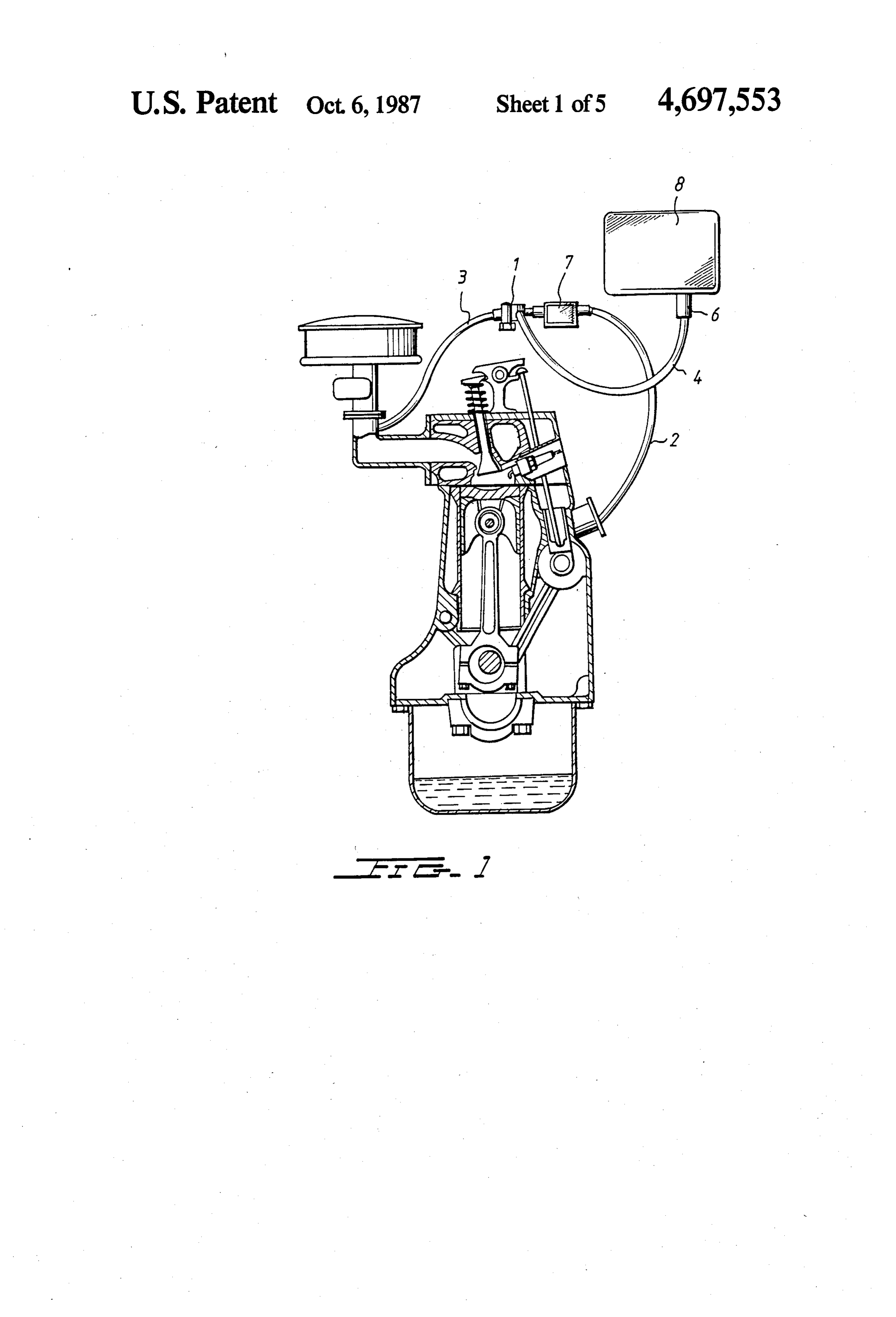
FIG. 1 shows the lubricating oil input system of the sent intotheengine. However, when the driver presses the present invention attached to an internal combustion brake, flow of oil may be reversed, in which the returning means (7) would receive the back flow of oil.
engine, wherein the piston is at the top position.
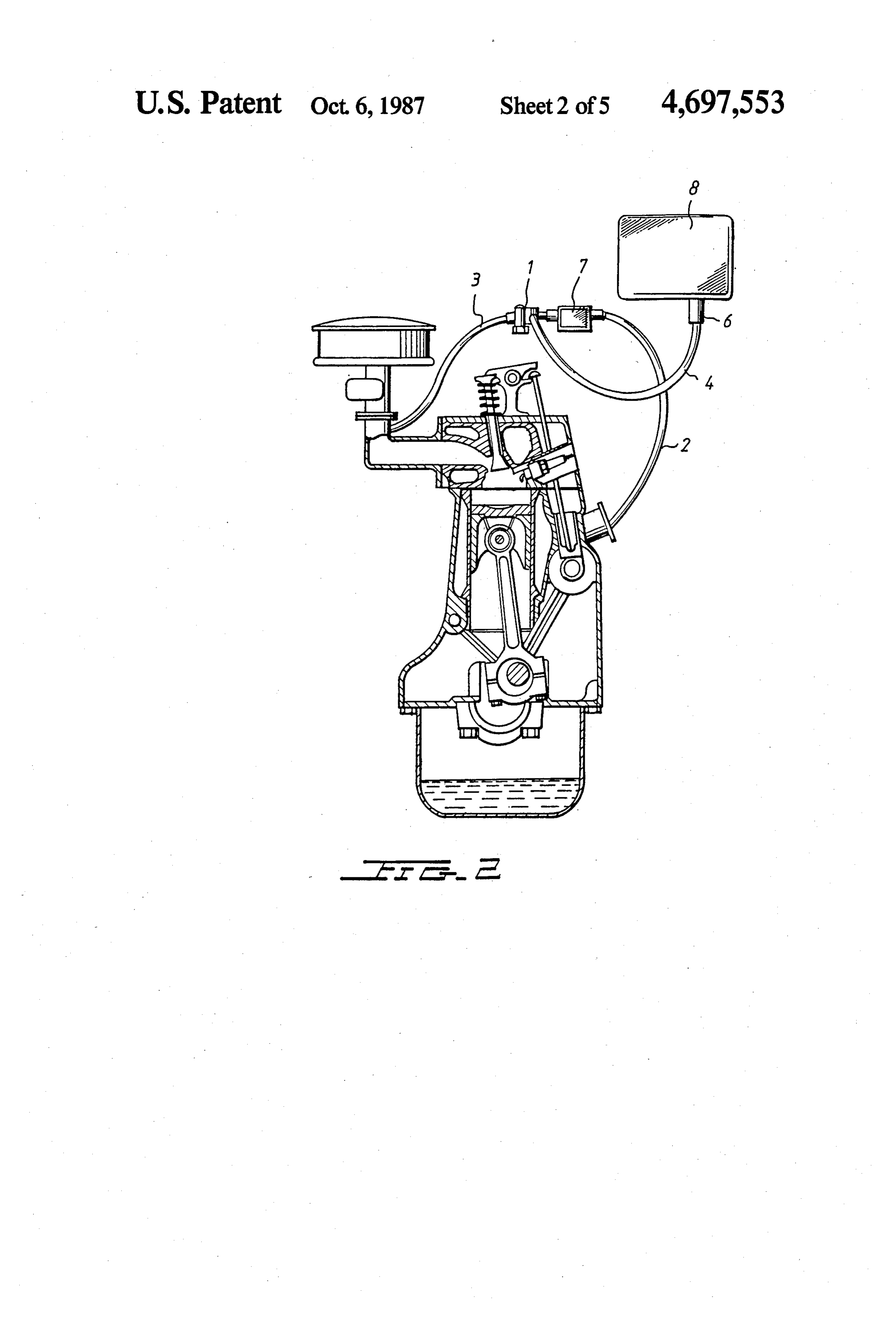
FIG. 2 shows the lubricating oil input system of the theAsabove various possible embodiments might be made of invention without departing from the scope
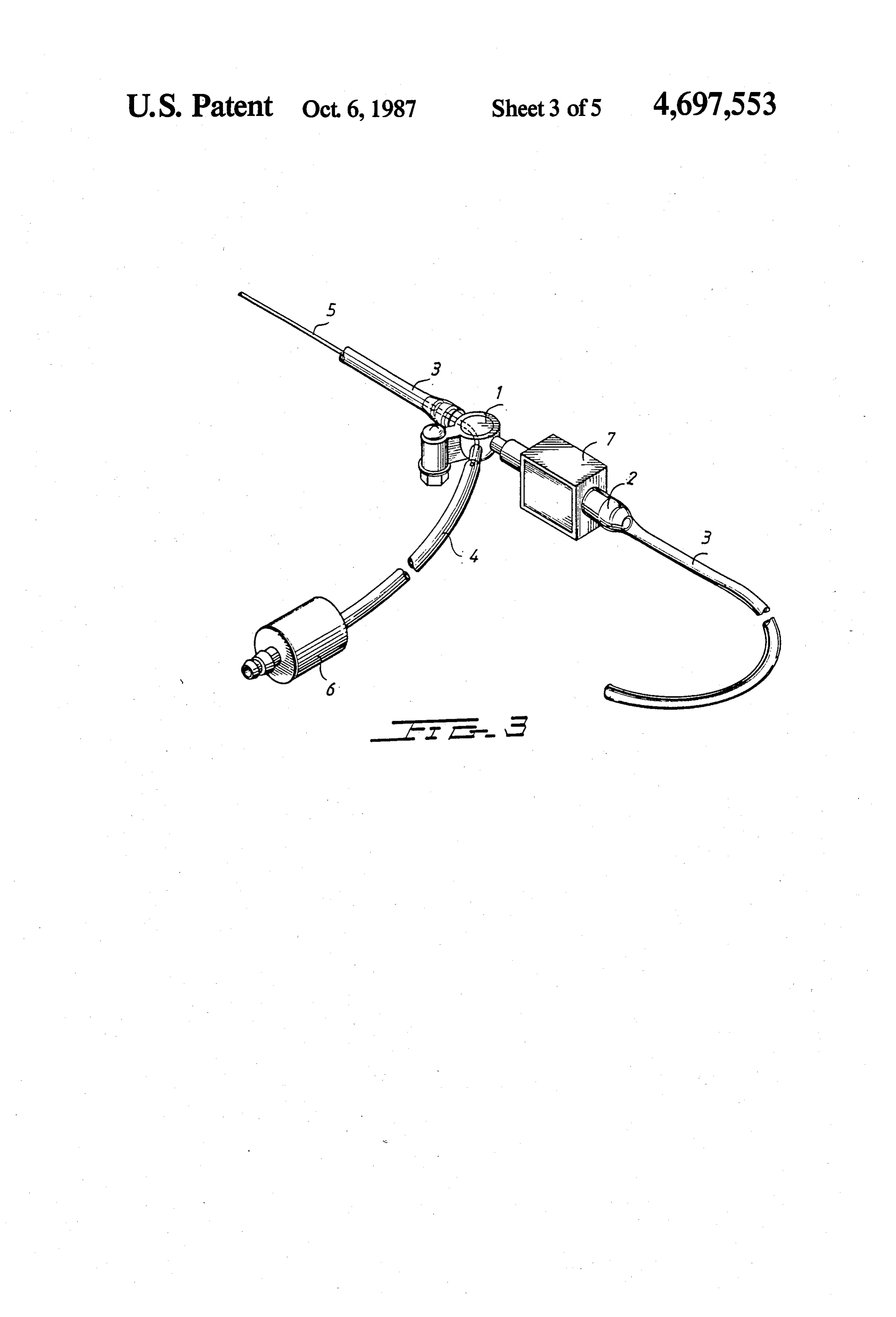
present invention attached to an engine, wherein the of the invention, piston is at the bottom position. it is to be understood that all matter FIG. 3 is perspective view of the lubricating oil input to be interpreted asshown herein described or in the accompany drawing is illustrative and not in a limiting system of the present invention. sense. Thus, it will be appreciated that the drawings are FIG. 4 is a cutaway view showing the interior of the exemplary of a preferred embodiment of the invention. returning means of the present invention. 45
I claim:
FIG. 5 is a cross-sectional view of the filter means of the present invention. 1. A lubricating oil input system which is connected to an internal combustion engine comprising:
DETAILED DESCRIPTION OF THE a joiner having a fixing seat to be fixed to the vehicle PREFERRED EMBOEDIMENT 50 body;
Referring to the drawings, the lubricating oil input a first ignition advance vacuum tube connected be system comprises a joiner (1), a first ignition advance tween said joiner and the distributor of said internal vacuum tube (3), a second ignition advance vacuum combustion engine;
tube (2), a connecting tube (4), a small tube (5), a filter a second ignition advance vacuum tube connected means (6), a returning means (7) and an oil tank (8). As 55 between said joiner and the carburetor of said in can be seen in FIG. 1 and FIG. 3, the joiner (1) is ar ternal combustion engine; ranged with a fixing seat to be fixed to vehicle (not a connecting tube connected between said joiner and shown). The second ignition advance vacuum tube (2) is an oil tank which is used for containing lubricating connected between the joiner (1) and the carburetor of oil and optionally containing an added cleaner; the engine (the carburetor is not shown in the draw- 60 a small tube which is disposed in said connecting ings). The first ignition advance vacuum tube (3) is tube, said joiner, and said second ignition advance connected between the joiner (1) and the distributor of vacuum tube;
the engine (the distributor is not shown in the draw a filter means which is disposed at the joint region of ings). The connecting tube (4) is connected between the said oil tank and said connecting tube, said filter joiner (1) and the oil tank (8) which contains lubricating 65 means comprising a filter medium to filter the lubri oil. A small tube (5) is disposed in the connecting tube cating oil which flows from the oil tank; (4), the joiner (1) and the second ignition advance vac a returning means which is disposed on said first uum tube (2). There is a filter means (6) (referring to ignition advance vacuum tube abutting against the
Page 8
joiner, said returning means comprising a separat- valve being fixed proximate to said aperture which ing plate to separate the returning means into two protrudes from one end of the returning means spaces, the left space having a returning tube con- housing so as to connect to said first ignition ad nected to said joiner and the right space having an Vance vacuum tube.
aperture on the right side wall thereof; a one-way 5 sk
Provenance
- Collection
- Cited prior art
- Original PDF
- patentimages.storage.googleapis.com →
- Filed
- 1986-08-11
- Pages
- 8
- Method
- pdftotext (the PDF's own text layer) + pdftoppm 300dpi page scans
- Source
- Google Patents bibliographic record
- Granted
- 1987-10-06
- Inventors
- Zong Z. Lie
- Transcribed from
- patentimages.storage.googleapis.com →