patent · US5300819
Automatic power regulator for induction type biogas generator
5 April 1994
Page 1 — bibliographic record
United States Patent (19) 11) Patent Number: 5,300,819 Lee (45) Date of Patent: Apr. 5, 1994 (54 AUTOMATIC POWER REGULATORFOR (56) References Cited NDUCTION TYPE BOGAS GENERATOR U.S. PATENT DOCUMENTS 4,211,932 7/1980 Geary, Jr. ............................. 290/52 (75) Inventor: Ching-Ping Lee, Hsinchu, Taiwan 4,262,209 4/1981 Berner .....................
73) Assignee: Industrial Technology Research Primary Examiner-A. D. Pellinen Institute, Hsinchu, Taiwan Assistant Examiner-Aditya Krishnan
Attorney, Agent, or Firm-Fish & Richardson 21 Appl. No.: 856,478 57 ABSTRACT Disclosed is an automatic power regulator for control ling an induction type biogas generator via an electri 22 Filed: Mar. 24, 1992 cally controlled governor. The biogas generator is di rectly coupled with a commercial AC power network.
The regulator controls the power output of the genera 51) int. Cl. ................................................ FO2G 3/00 tor to follow the power consumption of a load accord 52 U.S. C. ...................................... 307/47; 123/357; ing to the difference between the power output and the 123/358; 123/359; 123/3 power consumption. Positive and negative references 58) Field of Search ....................... 307/52, 57, 68, 47, are set to avoid oscillation of the system.
359, 3,350 2 Claims, 7 Drawing Sheets
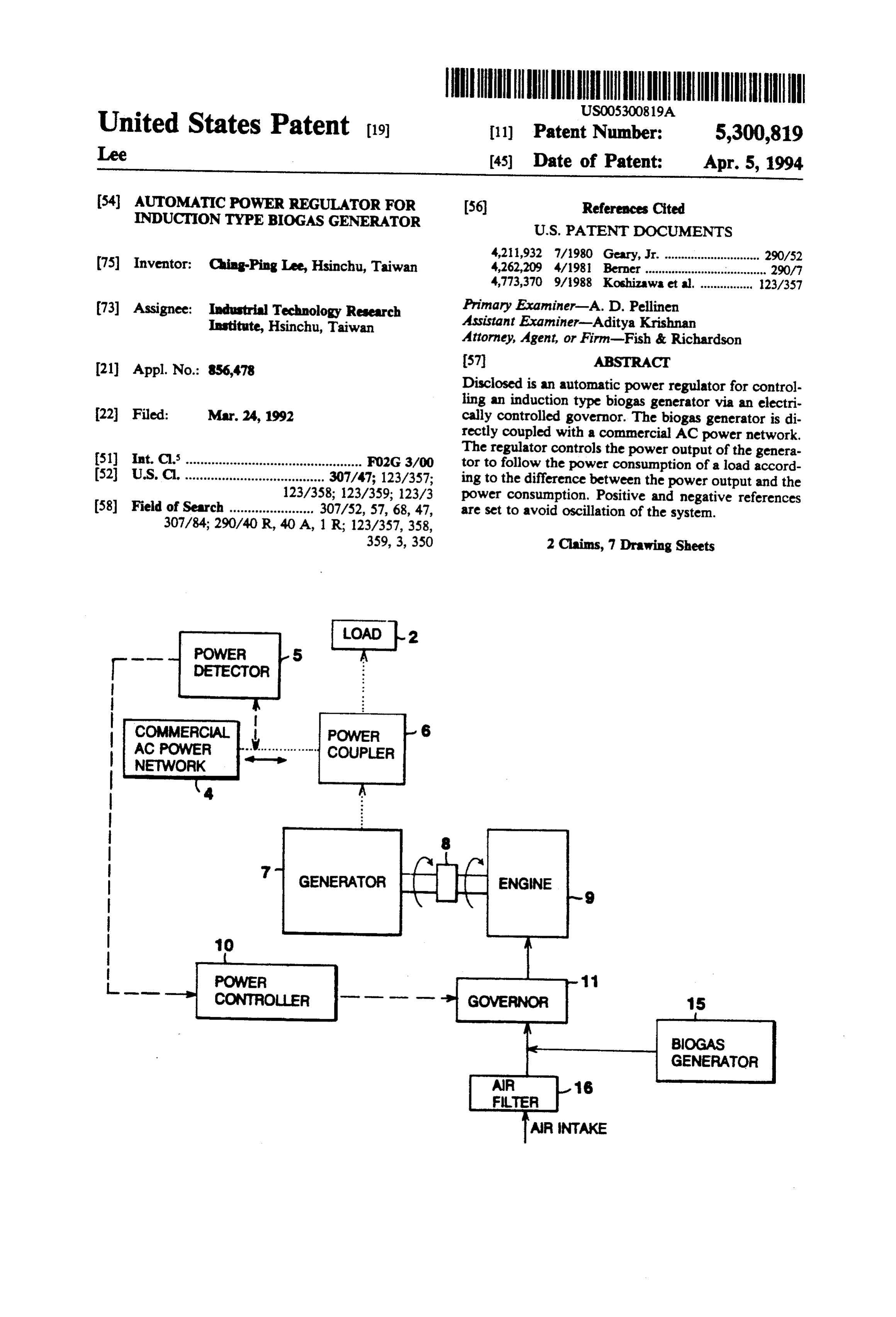
LOAD -2
DETECTOR
" " " COUPLER
BIOGAS
GENERATOR
Page 2
Drawing sheet — no readable text.
Page 3
Drawing sheet — no readable text.
Page 4
Drawing sheet — no readable text.
Page 5
Drawing sheet — no readable text.
Page 6
Drawing sheet — no readable text.
Page 7
Drawing sheet — no readable text.
Page 8
Drawing sheet — no readable text.
Page 9
AUTOMATIC POWER REGULATOR FOR SUMMARY OF THE INVENTION NDUCTION TYPE BOGAS GENERATOR It is therefore an object of this invention to provide a
FIELD OF THE INVENTION
power regulator for automatically controlling the in duction type biogas generator.
The present invention relates to an automatic power The power regulator according to the present inven regulator, especially to an automatic power regulator tion is featured in a power controller which controls the for an induction generator using a biogas engine as the amount of biogas intake according to the difference power source. 10 between the power output of biogas generator and the
BACKGROUND OF THE INVENTION
power consumption of load. Therefore less electricity is supplied by or fed into the commercial AC power net
The excrement and urine from pigs are highly-con work.
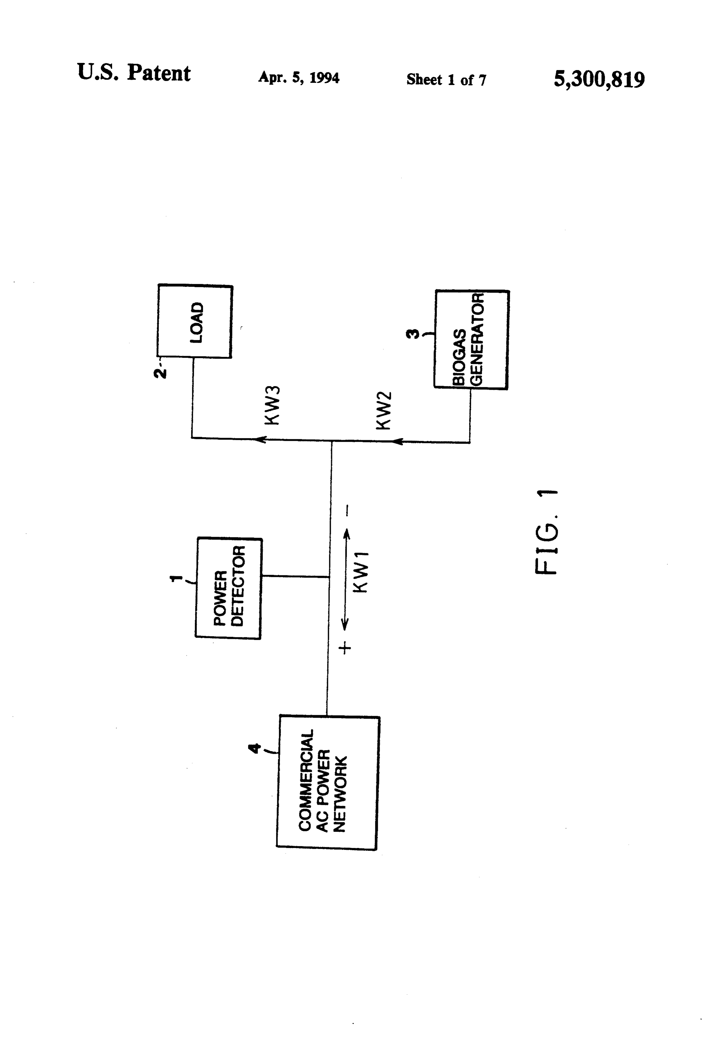
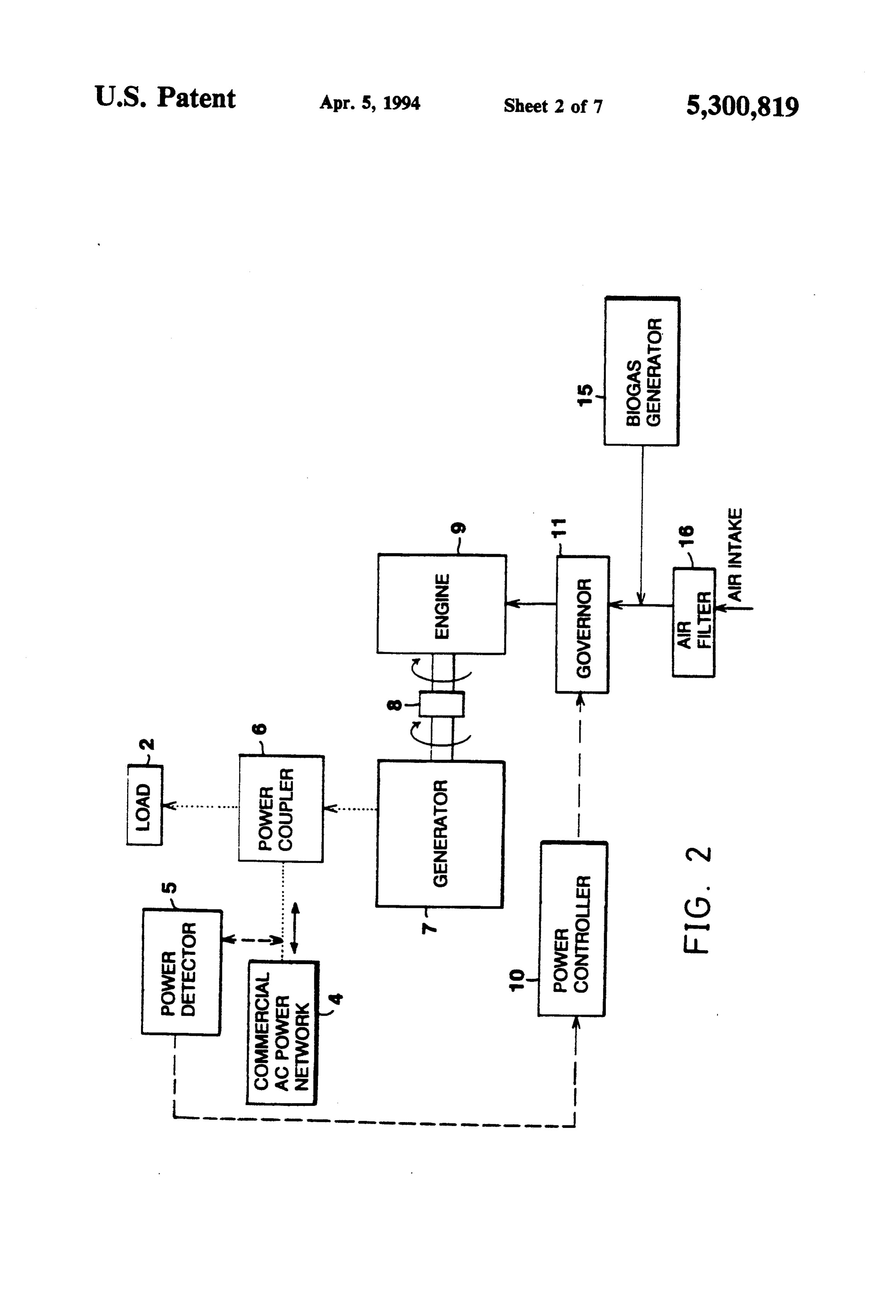
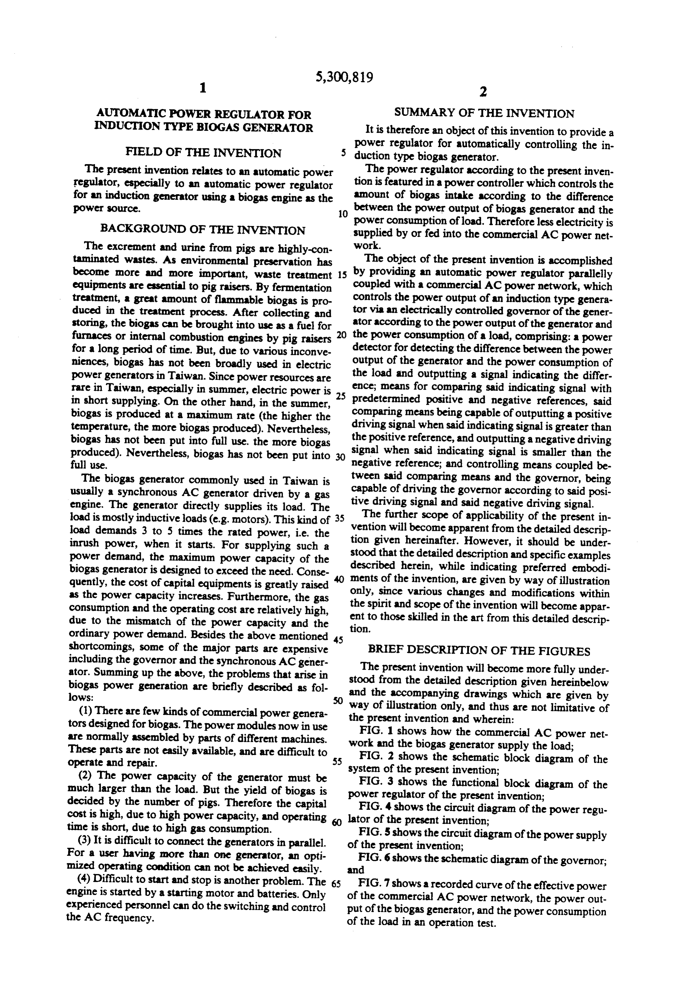
taminated wastes. As environmental preservation has The object of the present invention is accomplished become more and more important, waste treatment 15 by providing an automatic power regulator parallelly equipments are essential to pig raisers. By fermentation coupled with a commercial AC power network, which treatment, a great amount of flammable biogas is pro controls the power output of an induction type genera duced in the treatment process. After collecting and tor via an electrically controlled governor of the gener storing, the biogas can be brought into use as a fuel for ator according to the power output of the generator and furnaces or internal combustion engines by pig raisers the power consumption of a load, comprising: a power for a long period of time. But, due to various inconve detector for detecting the difference between the power niences, biogas has not been broadly used in electric output of the generator and the power consumption of power generators in Taiwan. Since power resources are the load and outputting a signal indicating the differ rare in Taiwan, especially in summer, electric power is 25 ence; means for comparing said indicating signal with in short supplying. On the other hand, in the summer, predetermined positive and negative references, said biogas is produced at a maximum rate (the higher the comparing means being capable of outputting a positive temperature, the more biogas produced). Nevertheless, driving signal when said indicating signal is greater than biogas has not been put into full use. the more biogas the positive reference, and outputting a negative driving produced). Nevertheless, biogas has not been put into signal when said indicating signal is smaller than the full use. negative reference; and controlling means coupled be The biogas generator commonly used in Taiwan is tween said comparing means and the governor, being usually a synchronous AC generator driven by a gas capable of driving the governor according to said posi engine. The generator directly supplies its load. The tive driving signal and said negative driving signal. load is mostly inductive loads (e.g. motors). This kind of 35 The further scope of applicability of the present in load demands 3 to 5 times the rated power, i.e. the vention will become apparent from the detailed descrip inrush power, when it starts. For supplying such a tion given hereinafter. However, it should be under power demand, the maximum power capacity of the stood that the detailed description and specific examples biogas generator is designed to exceed the need. Conse described herein, while indicating preferred embodi quently, the cost of capital equipments is greatly raised ments of the invention, are given by way of illustration as the power capacity increases. Furthermore, the gas only, since various changes and modifications within consumption and the operating cost are relatively high, the spirit and scope of the invention will become appar due to the mismatch of the power capacity and the tion. ent to those skilled in the art from this detailed descrip ordinary power demand. Besides the above mentioned 45 shortcomings, some of the major parts are expensive BRIEF DESCRIPTION OF THE FIGURES including the governor and the synchronous AC gener ator. Summing up the above, the problems that arise in stood The present invention will become more fully under biogas power generation are briefly described as fol and from the detailed description given hereinbelow lows: the accompanying drawings which are given by (1) There are few kinds of commercial power genera waypresent of illustration only, and thus are not limitative of tors designed for biogas. The power modules now in use theFIG. 1 invention and wherein:
shows how the commercial AC power net are normally assembled by parts of different machines. work and the biogas generator supply the load; These parts are not easily available, and are difficult to FIG. 2 shows the schematic block diagram of the operate and repair. 55 system of the present invention;
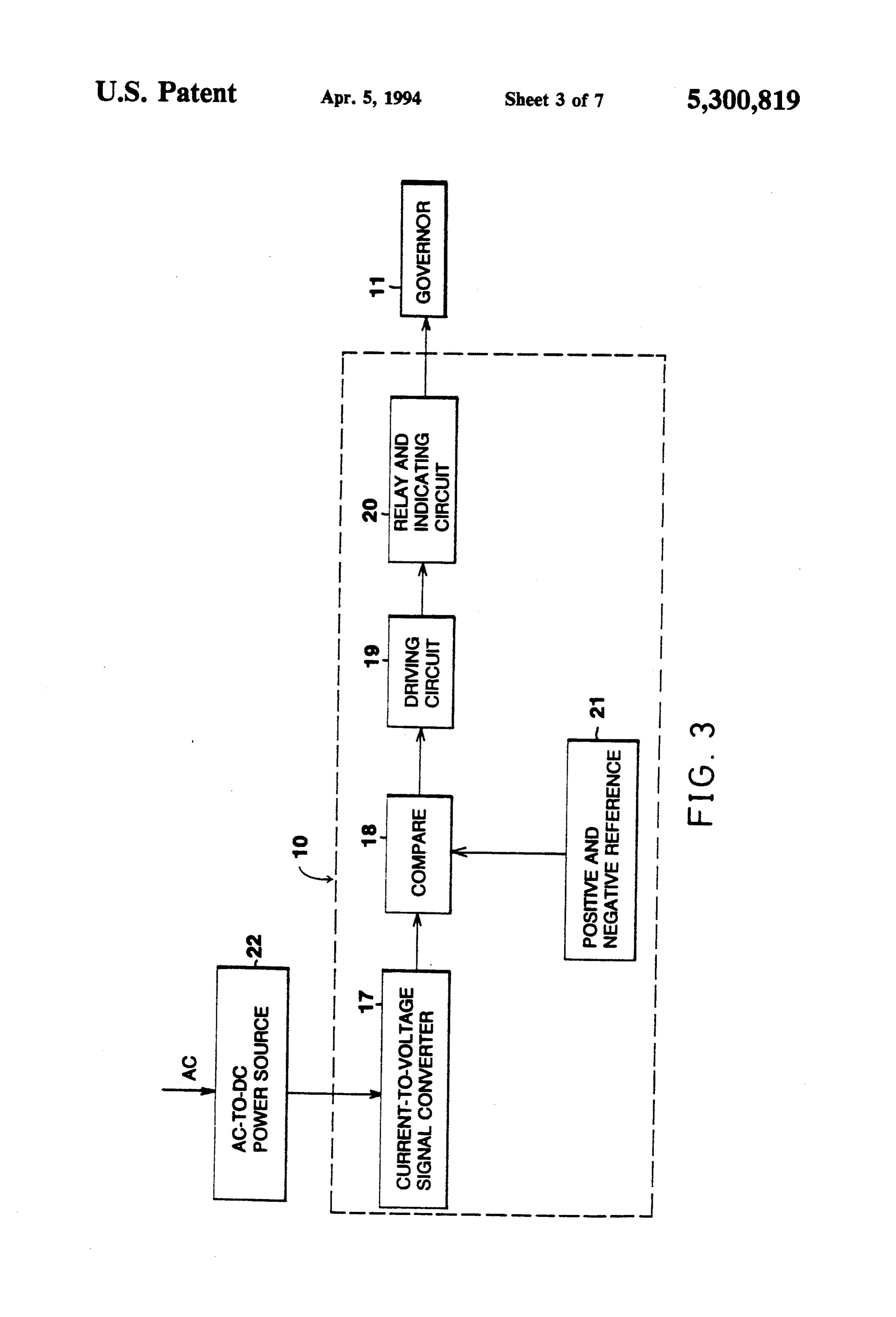
(2) The power capacity of the generator must be FIG. 3 shows the functional block diagram of the much larger than the load. But the yield of biogas is power regulator of the present invention; decided by the number of pigs. Therefore the capital cost is high, due to high power capacity, and operating lator of4theshows
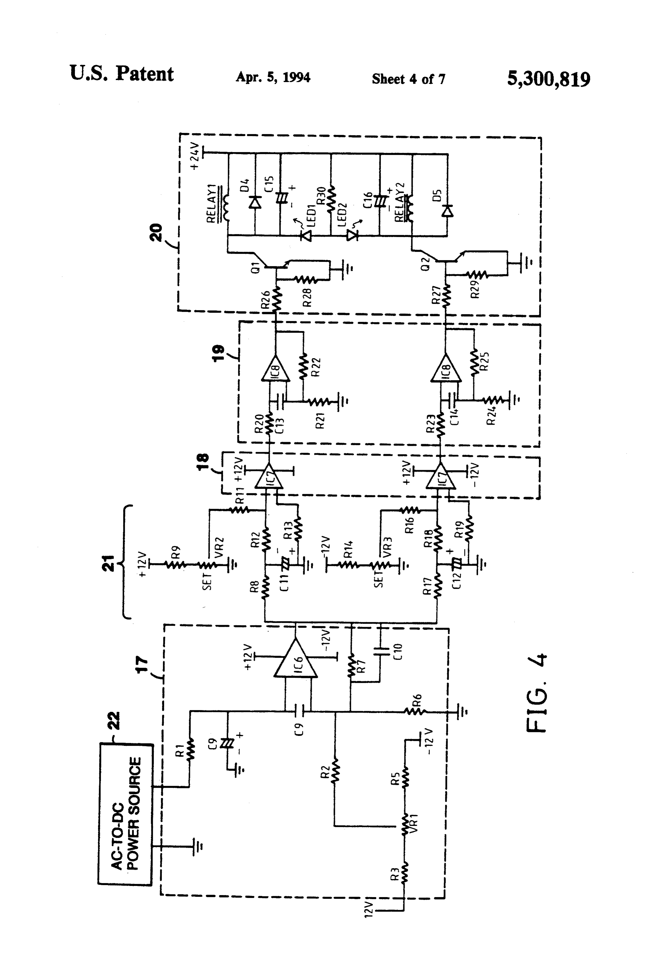
FIG. the circuit diagram of the power regu present invention;
time is short, due to high gas consumption.
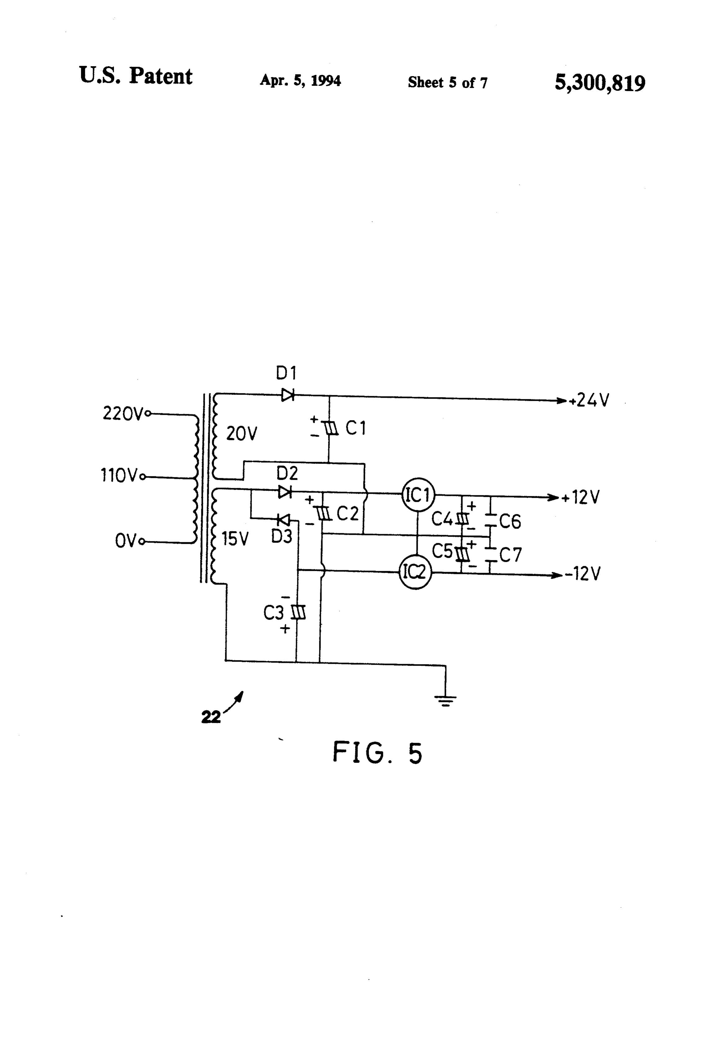
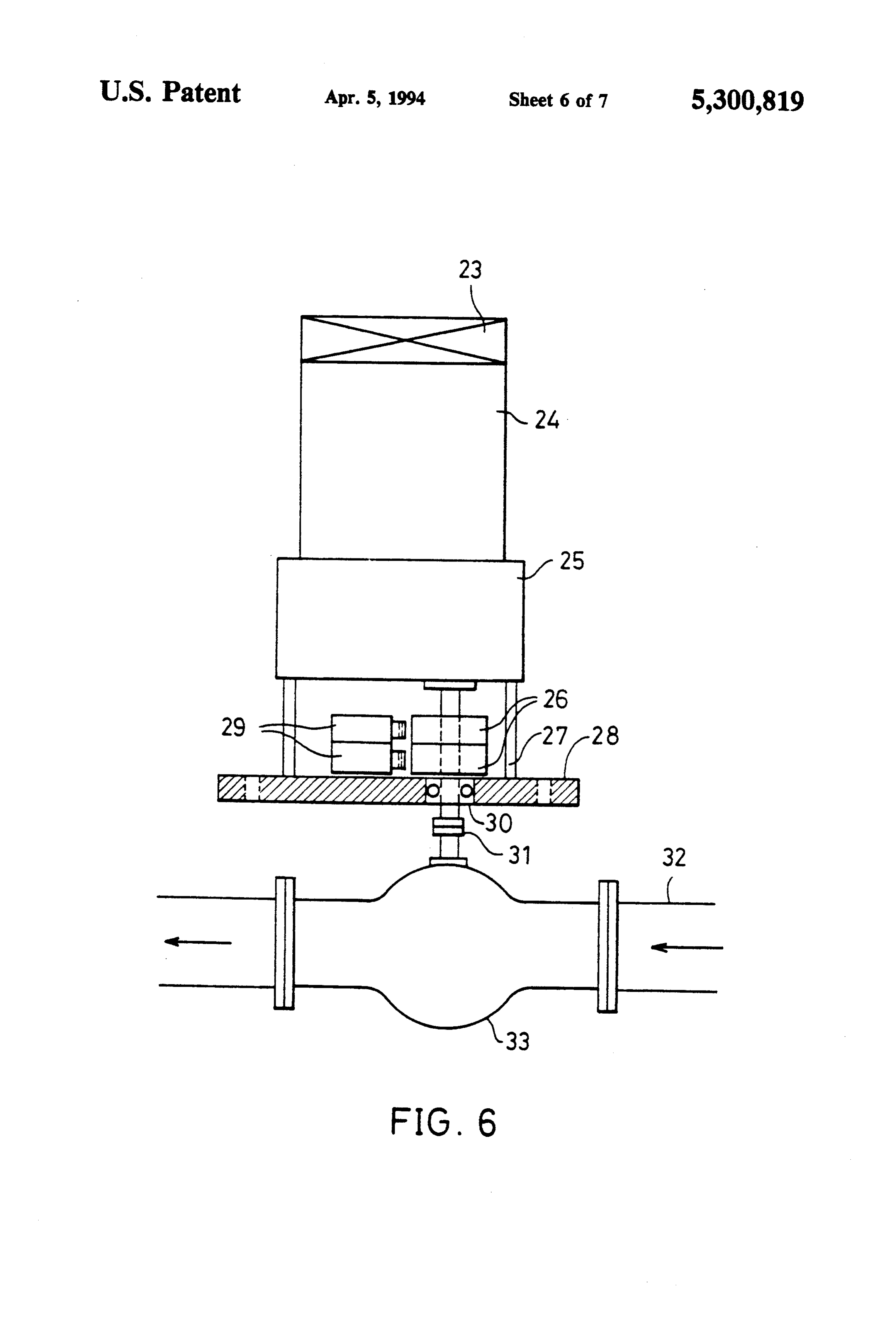
(3) It is difficult to connect the generators in parallel. of the present invention; diagram of the power supply FIG. 5 shows the circuit
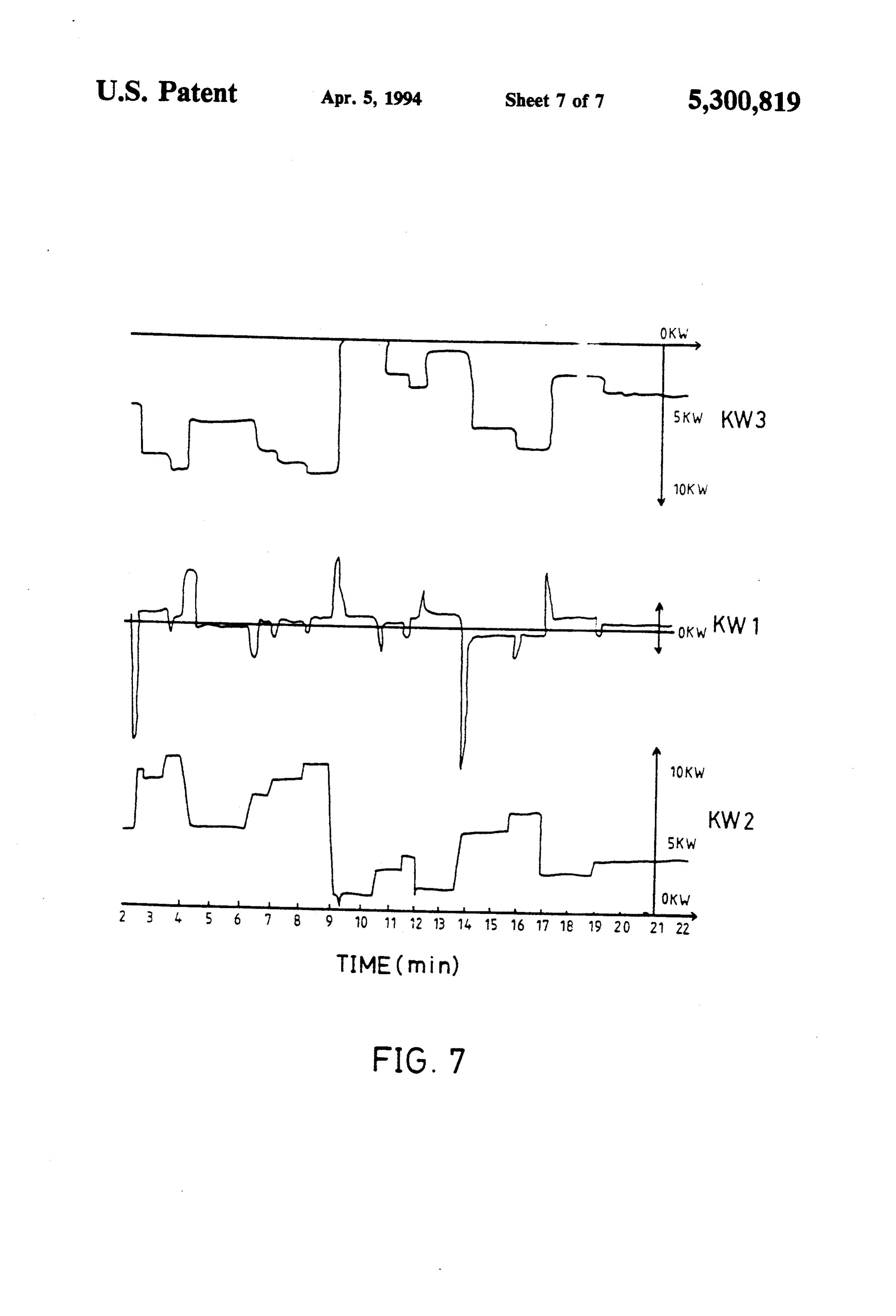
For a user having more than one generator, an opti FIG. 6 shows the schematic diagram of the governor; mized operating condition can not be achieved easily. and (4) Difficult to start and stop is another problem. The 65 engine is started by a starting motor and batteries. Only ofFIG.7 the shows a recorded curve of the effective power commercial AC power network, the power out experienced personnel can do the switching and control put of the biogas generator, and the power consumption the AC frequency. of the load in an operation test.
Page 10
DETALED DESCRIPTION OF PREFERRED Power detector 5 is a conventional device which is EMBODIMENT utilized to detect the effective power of the commercial AC power network, KW1. Conventional digital elec
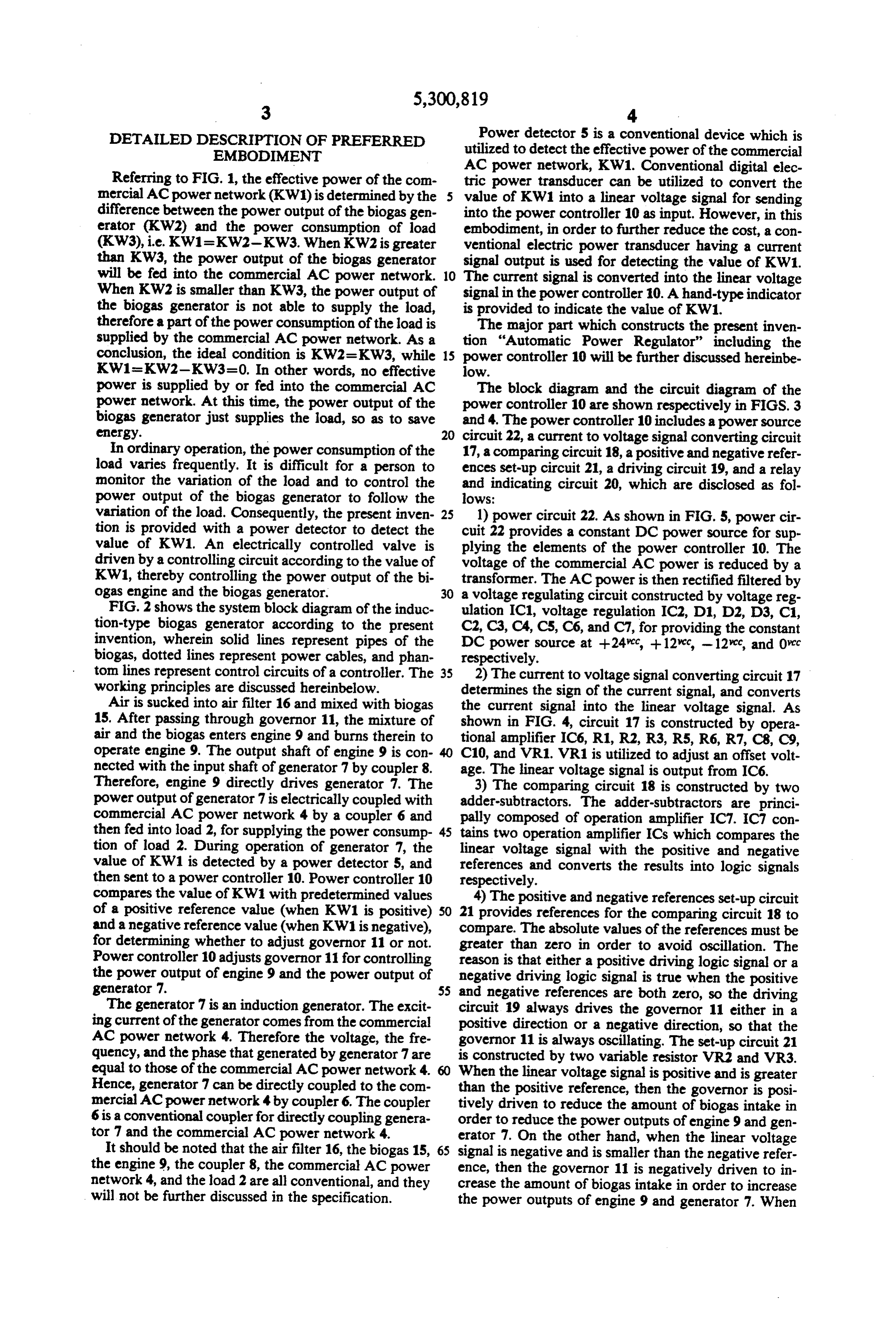
Referring to FIG. 1, the effective power of the com tric power transducer can be utilized to convert the mercial AC power network (KW1) is determined by the value of KW1 into a linear voltage signal for sending difference between the power output of the biogas gen into the power controller 10 as input. However, in this erator (KW2) and the power consumption of load embodiment, in order to further reduce the cost, a con (KW3), i.e. KW1=KW2-KW3. When KW2 is greater ventional electric power transducer having a current than KW3, the power output of the biogas generator signal output is used for detecting the value of KW1. will be fed into the commercial AC power network. 10 The current signal is converted into the linear voltage When KW2 is smaller than KW3, the power output of signal in the power controller 10. A hand-type indicator the biogas generator is not able to supply the load, is provided to indicate the value of KW1. therefore a part of the power consumption of the load is The major part which constructs the present inven supplied by the commercial AC power network. As a tion "Automatic Power Regulator' including the conclusion, the ideal condition is KW2=KW3, while 15 power controller 10 will be further discussed hereinbe KW1=KW2-KW3=0. In other words, no effective low.
power is supplied by or fed into the commercial AC The block diagram and the circuit diagram of the power network. At this time, the power output of the power controller 10 are shown respectively in FIGS. 3 biogas generator just supplies the load, so as to save and 4. The power controller 10 includes a power source energy. 20 circuit 22, a current to voltage signal converting circuit In ordinary operation, the power consumption of the 17, a comparing circuit 18, a positive and negative refer load varies frequently. It is difficult for a person to ences set-up circuit 21, a driving circuit 19, and a relay monitor the variation of the load and to control the and indicating circuit 20, which are disclosed as fol power output of the biogas generator to follow the lows:
variation of the load. Consequently, the present inven 25 1) power circuit 22. As shown in FIG. 5, power cir tion is provided with a power detector to detect the cuit 22 provides a constant DC power source for sup value of KW1. An electrically controlled valve is plying the elements of the power controller 10. The driven by a controlling circuit according to the value of voltage of the commercial AC power is reduced by a KW1, thereby controlling the power output of the bi transformer. The AC power is then rectified filtered by ogas engine and the biogas generator. 30 a voltage regulating circuit constructed by voltage reg FIG. 2 shows the system block diagram of the induc ulation IC1, voltage regulation IC2, D1, D2, D3, C1, tion-type biogas generator according to the present C2, C3, CA, C5, C6, and C7, for providing the constant invention, wherein solid lines represent pipes of the DC power source at +24.cc, +12cc, -12cc, and 0cc biogas, dotted lines represent power cables, and phan respectively.
tom lines represent control circuits of a controller. The 35 2) The current to voltage signal converting circuit 17 working principles are discussed hereinbelow. determines the sign of the current signal, and converts Air is sucked into air filter 16 and mixed with biogas the current signal into the linear voltage signal. As 15. After passing through governor 11, the mixture of shown in FIG. 4, circuit 17 is constructed by opera air and the biogas enters engine 9 and burns therein to tional amplifier IC6, R1, R2, R3, R5, R6, R7, C8, C9, operate engine 9. The output shaft of engine 9 is con 40 C10, and VR1. VR1 is utilized to adjust an offset volt nected with the input shaft of generator 7 by coupler 8. age. The linear voltage signal is output from IC6. Therefore, engine 9 directly drives generator 7. The 3) The comparing circuit 18 is constructed by two power output of generator 7 is electrically coupled with adder-subtractors. The adder-subtractors are princi commercial AC power network 4 by a coupler 6 and pally composed of operation amplifier IC7. IC7 con then fed into load 2, for supplying the power consump 45 tains two operation amplifier ICs which compares the tion of load 2. During operation of generator 7, the linear voltage signal with the positive and negative value of KW1 is detected by a power detector 5, and references and converts the results into logic signals then sent to a power controller 10. Power controller 10 respectively.
compares the value of KW1 with predetermined values 4) The positive and negative references set-up circuit of a positive reference value (when KW1 is positive) 50 21 provides references for the comparing circuit 18 to and a negative reference value (when KW1 is negative), compare. The absolute values of the references must be for determining whether to adjust governor 11 or not. greater than zero in order to avoid oscillation. The Power controller 10 adjusts governor 11 for controlling reason is that either a positive driving logic signal or a the power output of engine 9 and the power output of negative driving logic signal is true when the positive generator 7. 55 and negative references are both zero, so the driving The generator 7 is an induction generator. The excit circuit 19 always drives the governor 11 either in a ing current of the generator comes from the commercial positive direction or a negative direction, so that the AC power network 4. Therefore the voltage, the fre governor 11 is always oscillating. The set-up circuit 21 quency, and the phase that generated by generator 7 are is constructed by two variable resistor VR2 and VR3. equal to those of the commercial AC power network 4. When the linear voltage signal is positive and is greater Hence, generator 7 can be directly coupled to the com than the positive reference, then the governor is posi mercial AC power network 4 by coupler 6. The coupler tively driven to reduce the amount of biogas intake in 6 is a conventional coupler for directly coupling genera order to reduce the power outputs of engine 9 and gen tor 7 and the commercial AC power network 4. erator 7. On the other hand, when the linear voltage It should be noted that the air filter 16, the biogas 15, 65 signal is negative and is smaller than the negative refer the engine 9, the coupler 8, the commercial AC power ence, then the governor 11 is negatively driven to in network 4, and the load 2 are all conventional, and they crease the amount of biogas intake in order to increase will not be further discussed in the specification. the power outputs of engine 9 and generator 7. When
Page 11
the linear voltage signal is greater than the negative limit switches 29 will be triggered by cams 26 to shut off reference and is smaller than the positive reference, the the power of motor 24, so as to insure that the valve 33 governor 11 is not driven. The references are set so that rotates between these two positions. Valve 33 is not the difference between the positive and negative refer ences corresponds to 1/10 of the total power output fully closed at the idle position because the engine needs a little gas when idling.
capacity, preferably, so as to achieve a stable and eco The governor is a conventional device which is nomic operation. broadly used. The governor stated above is one of the 5) The driving circuit 19 amplifies the logic signal commercial which comes from the comparing circuit 18 in order to nors can alsoavailable governors. Other types of gover drive power transistors of the relay and indicating cir 10 It should also be notedinthat be utilized the present invention.
the fuel of the engine 9 is cuit 20. The driving circuit 19 is principally constructed not limited only to biogas. Other fuels like methane, by IC8 which contains two operational amplifiers.
6) The relay and indicating circuit 20 receives the used if the engine is adequately selectedetc.to can natural gas, petroleum gas, gasoline, fit also be
driving signals from the driving circuit 19 and drives relays and indicating LEDs which indicates the operat 15 ofFIG. the 7 is a record of the curves of the effective power commercial AC power network, KW1, the ing condition. Circuit 20 is principally constructed by two power transistors Q1 and Q2, RELAY1, and RE power output of the biogas generator, KW2, and the power consumption of the load, KW3, in an operation
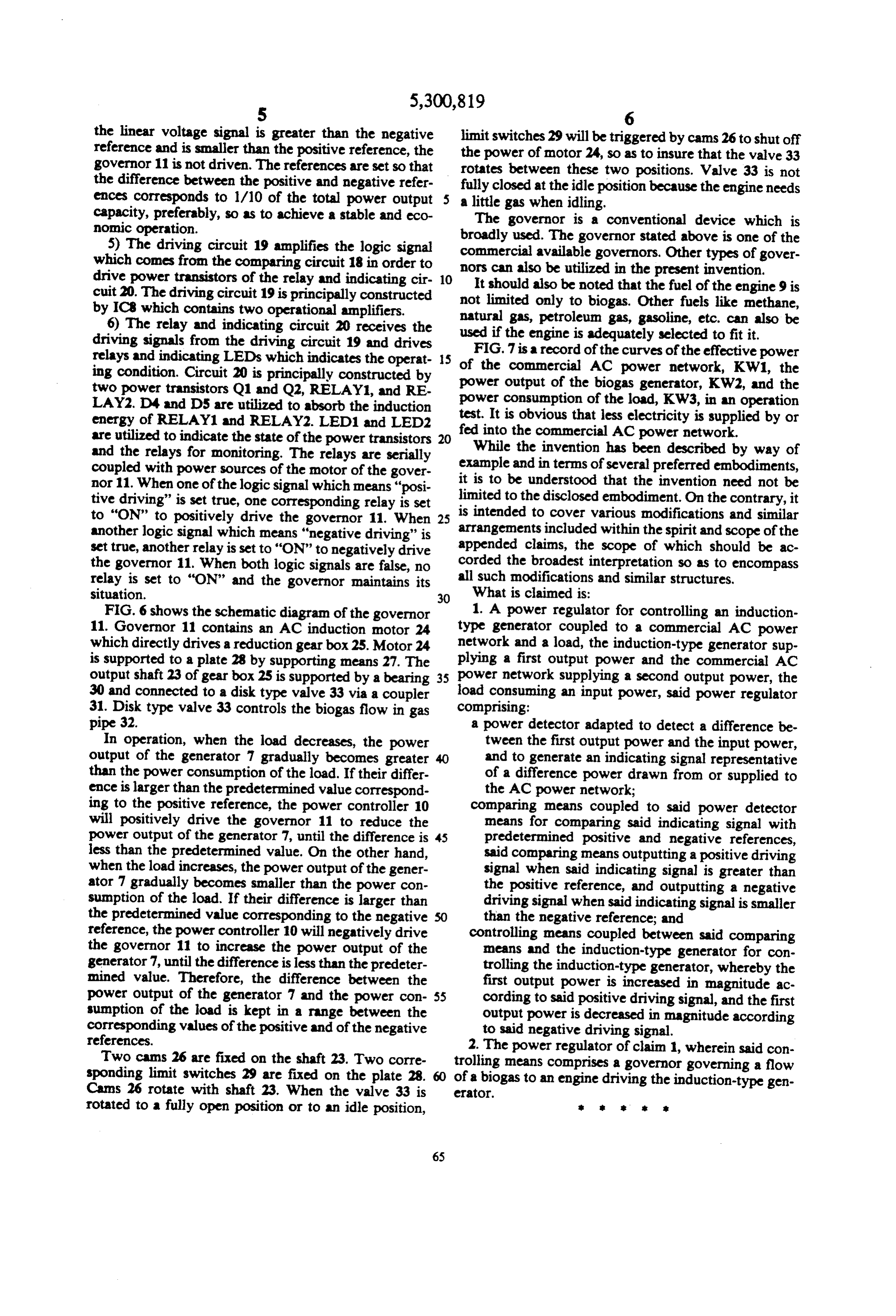
LAY2. D4 and D5 are utilized to absorb the induction energy of RELAY1 and RELAY2. LED1 and LED2 fed into test. It is obvious that less electricity is supplied by or are utilized to indicate the state of the power transistors 20 the commercial AC power network. and the relays for monitoring. The relays are serially While the invention has been described by way of coupled with power sources of the motor of the gover example and in terms of several preferred embodiments, nor 11. When one of the logic signal which means "posi it is to be understood that the invention need not be tive driving' is set true, one corresponding relay is set limited to the disclosed embodiment. On the contrary, it to “ON” to positively drive the governor 11. When 25 is intended to cover various modifications and similar another logic signal which means "negative driving' is arrangements included within the spirit and scope of the set true, another relay is set to “ON” to negatively drive appended claims, the scope of which should be ac the governor 11. When both logic signals are false, no corded the broadest interpretation so as to encompass relay is set to "ON" and the governor maintains its allWhat such modifications and similar structures. is claimed is:
situation. 30
FIG. 6 shows the schematic diagram of the governor 1. A power regulator for controlling an induction 11. Governor 11 contains an AC induction motor 24 type generator coupled to a commercial AC power which directly drives a reduction gearbox25. Motor 24 network and a load, the induction-type generator sup is supported to a plate 28 by supporting means 27. The plying a first output power and the commercial AC output shaft 23 of gear box 25 is supported by a bearing 35 power network supplying a second output power, the 30 and connected to a disk type valve 33 via a coupler load consuming an input power, said power regulator 31. Disk type valve 33 controls the biogas flow in gas comprising:
pipe 32. a power detector adapted to detect a difference be In operation, when the load decreases, the power tween the first output power and the input power, output of the generator 7 gradually becomes greater and to generate an indicating signal representative than the power consumption of the load. If their differ of a difference power drawn from or supplied to ence is larger than the predetermined value correspond the AC power network;
ing to the positive reference, the power controller 10 comparing means coupled to said power detector will positively drive the governor 11 to reduce the means for comparing said indicating signal with power output of the generator 7, until the difference is 45 predetermined positive and negative references, less than the predetermined value. On the other hand, said comparing means outputting a positive driving when the load increases, the power output of the gener signal when said indicating signal is greater than ator 7 gradually becomes smaller than the power con the positive reference, and outputting a negative sumption of the load. If their difference is larger than driving signal when said indicating signal is smaller the predetermined value corresponding to the negative than the negative reference; and reference, the power controller 10 will negatively drive controlling means coupled between said comparing the governor 11 to increase the power output of the means and the induction-type generator for con generator 7, until the difference is less than the predeter trolling the induction-type generator, whereby the mined value. Therefore, the difference between the first output power is increased in magnitude ac power output of the generator 7 and the power con 55 cording to said positive driving signal, and the first sumption of the load is kept in a range between the output power is decreased in magnitude according corresponding values of the positive and of the negative to said negative driving signal. references. 2. The power regulator of claim 1, wherein said con Two cans 26 are fixed on the shaft 23. Two corre trolling means comprises a governor governing a flow sponding limit switches 29 are fixed on the plate 28. of a biogas to an engine driving the induction-type gen Cans 26 rotate with shaft 23. When the valve 33 is erator.
rotated to a fully open position or to an idle position,
Provenance
- Collection
- Cited prior art
- Original PDF
- patentimages.storage.googleapis.com →
- Filed
- 1992-03-24
- Pages
- 11
- Method
- pdftotext (the PDF's own text layer) + pdftoppm 300dpi page scans
- Source
- Google Patents bibliographic record
- Granted
- 1994-04-05
- Inventors
- Ching-Ping Lee; Industrial Technology Research Institute ITRI
- Transcribed from
- patentimages.storage.googleapis.com →