patent · US2738861
Engine cylinder lubricating means
20 March 1956
Page 1
Drawing sheet — no readable text.
Page 2
United States Patent Office 1.
Patiented Mar. 20, 1956
ture system.
considerably increasing the cost
of the complete
It is therefore an object of the invention to devise a
ENGINE CYLNDER LUBRICATING MEANS simple and reliable device that can readily be joined with 5 a high-pressure lubricant circulation system to apply to
Günther Wilhelm Emele, Munich-Obermenzing, and Otto the piston-run surfaces of the cylinders or the like spots Hirsch, Beiberach (Riss), Germany, assignors to Krauss
Maffei Aktiengesellschaft, Munich-Allach, Geriuany, a to be additionally lubricated an accurately metered and constrainedly delivered quantity of lubricant from the corporation of Germany circulatory system by means of a metering fresh-oil pump
Application July 9, 1952, serial No. 297,958 10 of the type requiring, for accurate metering, the mainte nance of an only slight pressure at its suction side.
7 Claims. (Cl. 184-6) To this end, and in accordance with the invention, the piston-run surfaces of the engine cylinders are lubri
The invention relates to devices for lubricating the pis 5 cated with lubricant branched-off from the high-pressure lubricant circulation system of the engine which is sup ton-run surfaces of the cylinders of reciprocating engines, plied in cleaned condition to the suction side of an inter particularly internal-combustion engines, with an additional oil pump of adjustable delivery.
the aid of posed fresh-oil lubricating pump of the above-mentioned type at a slight and still permissible pressure and in a
It is a known expedient to use such a pump for addi tionally lubricating the cylinder slide surfaces with ac pre-metered lubrication.
quantity as required for the desired cylinder
In such a device, the branched-off lubricant curately metered quantities of fresh oil. Today, how line leading from a pressure point of the high-pressure ever, such a fresh-oil lubrication is used only rarely with circulatory system to the fresh-oil pump extends first internal-combustion engines because the known fresh-oil through a springless pressure-reduction device and thence lubricating devices are too cumbersome and are dependent . through an oil filter or strainer with a pertaining pressure upon careful attendance since lack of fresh oil due to 25 relief valve.
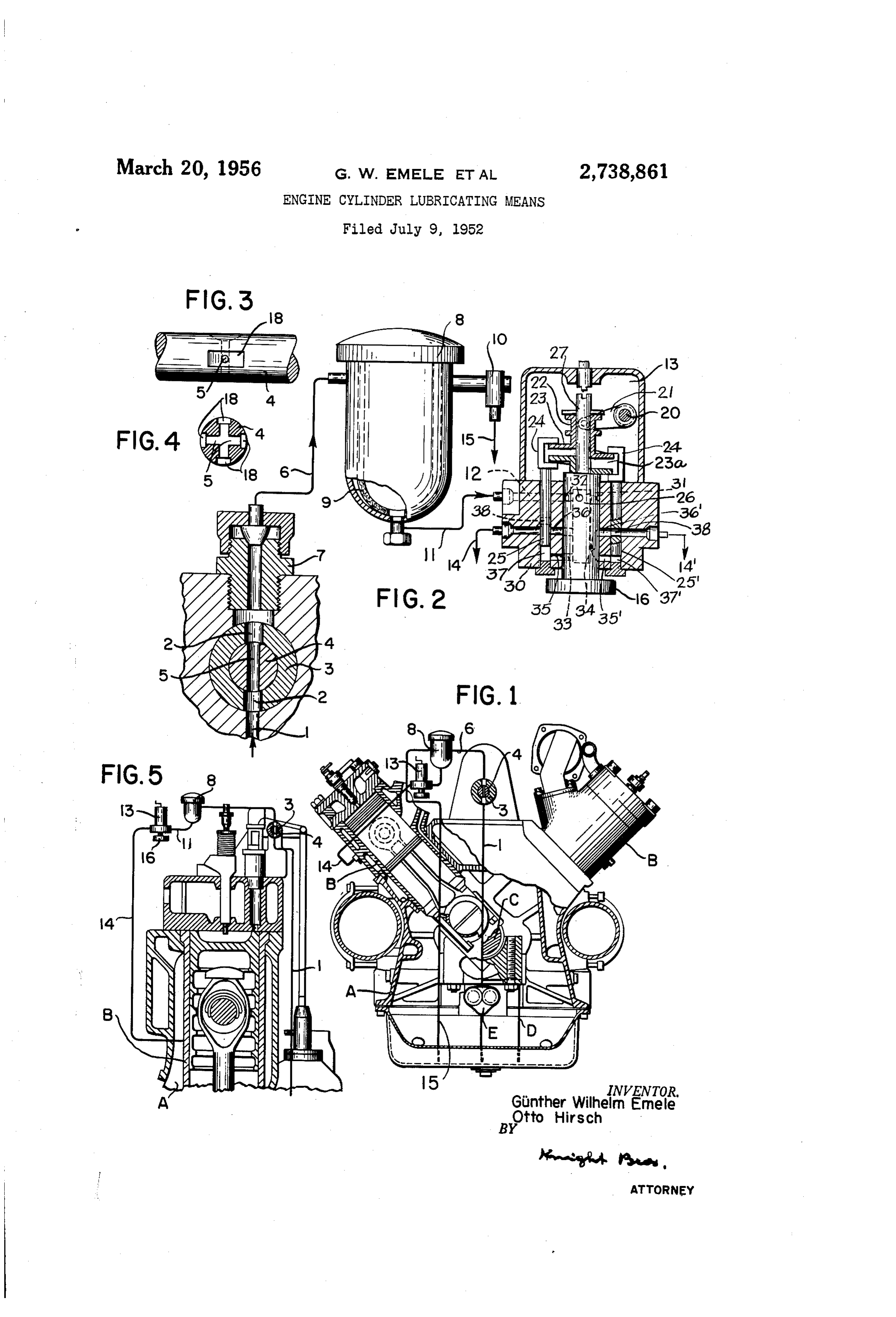
inattentive maintenance may endanger the engine. !: These and other features of the invention will be ap On the other hand, an additional and accurately ad parent from the following description in conjunction with justable lubrication of the piston-run surfaces is highly the embodiment of the invention exemplified by the draw desirable especially in large internal-combustion engines ing in which: - operating with high combustion pressures. Certain known 30 Fig. 1 shows a partially sectional front view of an en lubricating pumps of small size, composed of a number gine with a superimposed schematic illustration of a lub of pump elements, and delivering through separate pres ricating device according to the invention; sure lines a metered and accurately adjustable oil quan Fig. 2 is a non-detailed illustration of the lubrication tity to the respective spots to be lubricated, are suitable device showing the pertaining pressure-reduction means only for the application of fresh oil. For instance, these and pump in cross section;
pumps cannot be inserted into the circuit of a pressure Fig. 3 is a partial side view and Fig. 4 is a cross sec lubrication system because their working and control pis tion of a shaft member pertaining to the device accorring tons fit closely against their respective bores so that.im to Figs.1 and 2; and purities of the circulating pressure oil collecting in the nar Fig. 5 shows schematically a modified embodiment. row.interstices would soon impede the pump movements, 40 of a lubricating device according to the invention super desires, these fresh-oil lubricating pumps deliver the re imposed upon a partial and sectional view of an engine quired and adjusted oil quantity only when the suction cylinder structure.
side, common to all pump elements, is not subjected to over pressure or to more than a slight pressure gradient. of InanFigs. 1 and 5, the crankcase and oil sump structure internal-combustion piston engine is represented
Otherwise always the maximum quantity is delivered to 45 at A. Joined with the structure are the cylinders B whose the spots to be lubricated. Consequently, the provision respective reciprocating pistons act upon the crankshaft of a fresh-oil lubricating pump within the circuit of a C. of the engine. The engine is equipped with a high circulatory pressure lubrication system would be feasible pressure lubrication system which includes a main lubri only if at the suction side of this pump the circulating cation pump E and a circulation system. The lubricant pressure oil had no pressure or only a slight pressure, 50 circulation system, serving to pressure lubricate the main a well as a certain minimum degree of purity. crankshaft bearings and other component engine parts, . . While it has also become known to provide the lubri is represented by an only fragmentary showing of a con cant circulation system of machines with pressure re duit circuit D which extends from the pressure side of gulating devices followed by an oil strainer, these known 55 pump E to the points to be lubricated and thence back to regulating devices are attached to the lubricant circulation the oil sump.
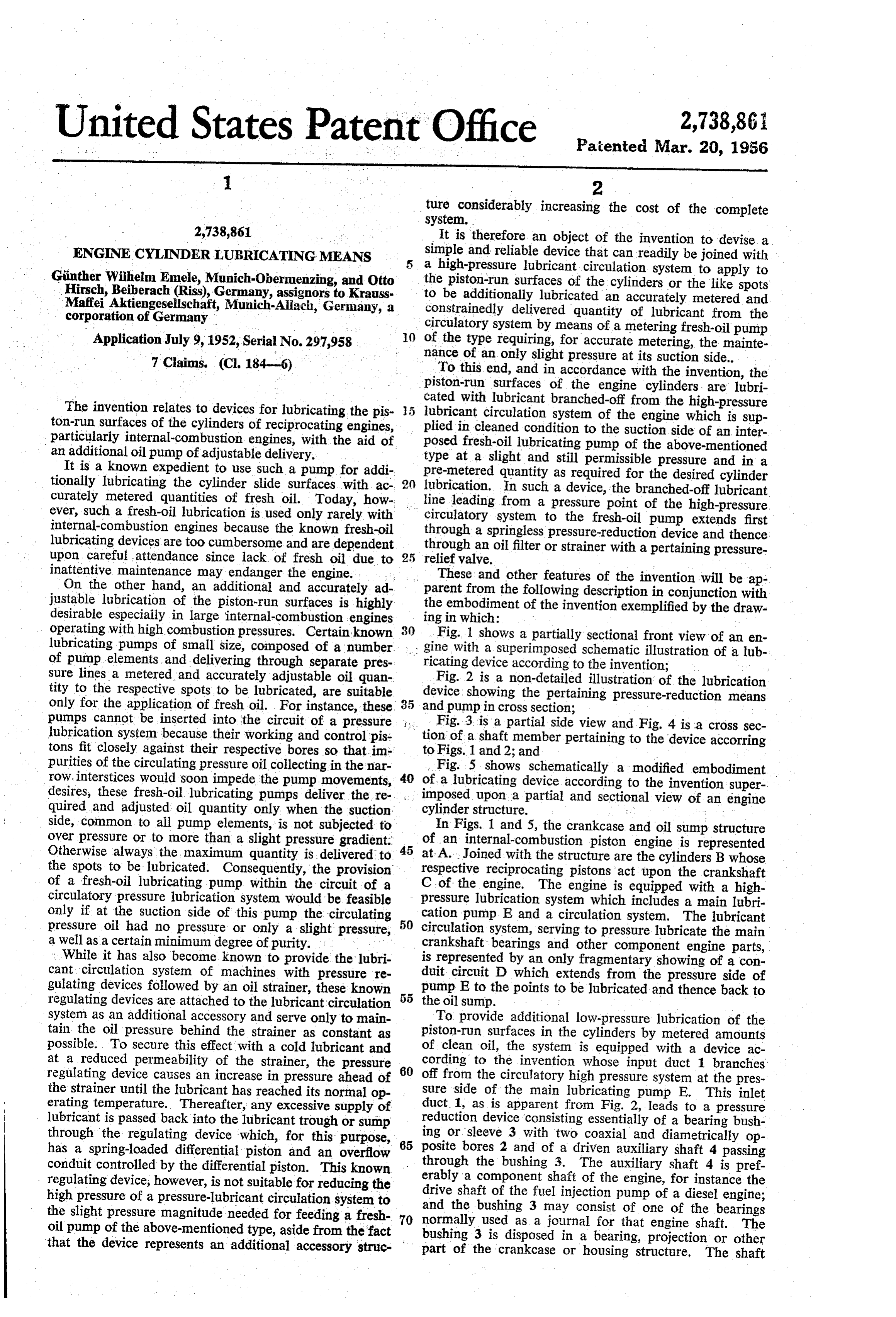
system as an additional accessory and serve only to main To provide additional low-pressure lubrication of the tain the oil pressure behind the strainer as constant as piston-run surfaces in the cylinders by metered amounts possible. To secure this effect with a cold lubricant and of clean oil, the system is equipped with a device ac at a reduced permeability of the strainer, the pressure 60 cording to the invention whose input duct 1 branches regulating device causes an increase in pressure ahead of off from the circulatory high pressure system at the pres the strainer until the lubricant has reached its normal op sure side of the main lubricating pump E. This inlet erating temperature. Thereafter, any excessive supply of duct. 1, as is apparent from Fig. 2, leads to a pressure lubricant is passed back into the lubricant trough or sump reduction device consisting essentially of a bearing bush through the regulating device which, for this purpose, 65 posite ing or sleeve 3 with two coaxial and diametrically op has a spring-loaded differential piston and an overflow bores 2 and of a driven auxiliary shaft 4 passing conduit controlled by the differential piston. This known through the bushing 3. The auxiliary shaft 4 is pref regulating device, however, is not suitable for reducing the erably a component shaft of the engine, for instance the drive shaft of the fuel injection pump of a diesel engine;
high pressure of a pressure-lubricant circulation system to the slight pressure magnitude needed for feeding a fresh 70 and the bushing 3 may consist of one of the bearings normally used as a journal for that engine shaft. The oil pump of the above-mentioned type, aside from the fact that the device represents an additional accessory struc bushing 3 is disposed in a bearing, projection or other part of the crankcase or housing structure, The shaft
Page 3
4 has one or several bores 5 which extend diametrically 36, 36". The bore 33, during the revolution of member through the shaft 4 or are directed at an angle to each 26, communicates intermittently with the bores 35, 35' other (see Figs. 3, 4). The shaft bores 5 and the open and thus communicates alternately with the spaces 37, 37 ings 2 lie in a common cross sectional plane so that they beneath the respective pistons 25, 25". At least one of are in registry with one another in a given angular po 5 the bores 32 is always in communication with the suction sition of the shaft. One of the bores 2 communicates inlet duct 12. The oil flows under slight pressure from with the oil inlet duct 1 while the other bore is con duct 12 through one of the bores 32 into the hollow 31 nected with an oil line 6, for instance by means of a and passes, in the position shown, through the bores 33 customary screw nipple or cap nut connection 7. When and 35 into the cylinder space 37 beneath the piston 25. the auxiliary shaft 4 is turning in any direction, the shaft 0 Each piston has a passage 38 or 38', which connects bores interconnect the openings 2 of bushing 3 so that the bores 36, 36 with the oil outlet ducts 14, 14' only the high-pressure inlet duct 1 communicates with line 6 during the lower portion of the piston stroke, for instance during intermittent and short-lasting periods of time. As when the piston 25' reaches the illustrated position. a result the oil line 6 is supplied with oil of a reduced Assume that piston 25 is raised and that piston 25' pressure depending upon the number and cross section is moving downward and has reached a point close to its of the bores 5 in the auxiliary shaft 4. At the same time, lower end of travel. Then, during the nearly completely the device acts to some degree also in a metering sense. upward stroke of piston 25, an amount of oil is drawn The oil line 6 is connected to an oil filter 8 of the known into the chamber 37 through the bores 33 and 35 from type whose housing is partitioned into two chambers by the interior 3 of member 26. Shortly thereafter the a filtering insert 9. The chamber surrounding the insert 20 chamber 37 is closed due to the fact that the bore 33 9 communicates with a relief valve 10 whose outlet con of member 26 passes out of register with the bore 35. duit 15 leads back to the oil trough or sump. The valve The piston 25 then remains in the raised position until 10 passes the major portion of the supplied quantity of the member 26 reaches a point of revolution at which oil back to the sump. The inner filter chamber enclosed the cam device 23, 23a pushes the piston downward. by the insert 9 is connected with an oil line 11 which 25 During its downward movement, the piston 25 will reach carries only the small quantity of oil required for the a position corresponding to the position illustrated for lubrication of the piston-run surfaces of the engine cyl piston 25", wherein the groove 34 of member 26 inter inders. Line 11 leads to the suction inlet structure 12 connects the ducts 35' and 36". When the piston 25' common to the pump elements of a lubricating pump 13 pushes downwardly further and reduces the volume of designed only for operation with fresh or clean oil. The 30 the chamber underneath, the quantity of oil previously outlet side of pump i3 is connected by respective lines enclosed in this chamber is forced through duct 35", groove 14 with the individual cylinders. 34, duct 36, and passage 38' to the oil outlet 14'. Simi The fresh-oil pump 13 is of the positive displacement lar action of piston 25 will thus alternately cause a meas type having gear or plunger elements which issue ac ured quantity of oil to be discharged through the oil curately dosed amounts of oil at low pressure. As men 35 outlet 4.
tioned, pumps of this kind are known as such. Their The piston operation described in the foregoing is con movable elements have the close fit required for main trolled by a cam device. As described above, this device taining a constant volumetric output, provided the oil comprises a cam disc 23a firmly joined with the shaft 27 pressure at the pump inlet side has a sufficiently low pres of the revolving pump member. Another cam member sure. The pump is driven by a gear 16 preferably from 40 23, revolving together with the member 23a, is axially the crankshaft of the engine or from another shaft, such displaceable by means of the sleeve 22, the arm 21, and as the cam shaft or auxiliary shaft, deriving its motion the shaft 20.
from the engine crankshaft. It will be understood that When the axial position of cam member 23 is adjusted the pump E of the main lubrication system schemati so that it touches cam member 23a, their total pitch or cally indicated in Fig. 1, as well as the auxiliary shaft 45 axial cam length is about equal to the vertical spacing 4 of the pressure reduction device are likewise driven between the two arms of the bracket 24 with which the from the crankshaft. piston 25 is connected. Consequently, when the shaft Fig. 2 illustrates the structural details of a well-known 27 is revolving, the cam device 23, 23.u runs idle and no type of fresh-oil pump utilized in the cylinder-lubricating lifting movement of the piston 25, or of the other piston, device constituting the invention. It will be understood 50 is effected. Consequently, no lubricant is delivered. that the structure of this fresh-oil pump in itself is not When the cam member 23 is shifted upwardly by cor part of the present invention, but merely a combined part respondingly setting the shaft 20 to the position shown in thereof. The pump 3 of Fig. 2 is equipped with the Fig. 2, the delivery can be set to any value up to the avail usual device for adjusting the delivered output quantity. able maximum. Assume that the cam member 23 is This device comprises a shaft 20 which stands transversely 55 lifted off the member 23a the full amount as shown in across the pump housing and carries an arm 2 whose Fig. 2; then the bracket 24 is also lifted until its lower bifurcated end straddles a grooved sleeve 22 and has pins arm nearly abuts against the lower cam face of member slidably engaging the groove of the sleeve. Sleeve 22 is 23a. With the position of shaft revolution shown, the joined with the piston-driving cam member 23. Axial pump is set for maximum delivery, because the pump displacement of sleeve 22 together with its cam member 60 stroke produced by the cam device is now a maximum 23 with respect to cam member 23a by means of shaft so that the chamber 37 reaches maximum volume at the 20 and arm 21 causes a corresponding change in the end of the suction stroke.
effective stroke of the pump plungers, as is hereinbelow When the cam member 23 is lifted only part of the more fully described. available displacement, for instance so that pump supplies As shown in Fig. 2, the revolving pump member driven one half of the maximum quantity, the bracket 24, when from the gear 16 comprises an upper shaft portion 27 in its uppermost position, is lifted a lesser amount than and a lower shaft portion 26. The lower portion 26 for the above-mentioned maximum. Consequently, the has a central hollow 3 with lateral openings 32 dis piston has a shorter stroke length and the delivered quan tributed over the periphery and has a groove 34 at one tity is reduced accordingly.
point of the periphery, this groove not being in com it will be recognized that the above-mentioned regu munication with the hollow 3. The block 30 in which the latable operation is secured only as long as the oil pres member 26 is revolvably mounted has a number of axially sure on the inlet side of the pump is below a small limit directed bores, such as those denoted by 25 and 25", value. If this value is exceeded, the oil pressure, acting for receiving the respective pump pistons. The block 30 in the above-mentioned chambers 37 and 37', will always has a group of bores 35, 35' and a second group of bores 75 lift the piston 25 or 25' as far as the piston will go

Page 4
until the lower arm of its bracket 24 abuts against the the line. 11 to the common6 suction portion 12 of the lower cam face of cam member 23a. Assume, för in pump 13 is further reduced to the slight pressure required stance, that the inlet pressure of the pump is too high; for the satisfactory operation of a fresh-oil pump and has: then the pressure beneath the piston will lift it all the way: only the small quantity needed for having pump 13 supply up until the bracket 24, abuts against cam member 23a. the points to be lubricated with cleaned and accurately Consequently, the pump will then always deliver maxi metered quantities of oil in accordance with the adjust mum quantities regardless of the setting of the cam device. ment of the individual pump elements. . . . . s To prevent the temporary and shortlasting passage be The invention is not limited to the particular embodi tween inlet duct 1 and oil line 6 from becoming reduced or obstructed at the transitions between the openings 2 10 ment a device specifically illustrated and described. For instance,;
according to the invention may be used with any and the bore 5, due to any axial displacements of the machines, for instance machine tools, which are equipped auxiliary shaft 4 or due to inaccuracies in the manu with a circulatory high-pressure lubrication system and facture of the radial bores 5, the openings of the radial have additional points to be lubricated with fresh oil. bores: 5 are preferably given an arcuate groove shape We claim: ?: : : :: : - ';'; :. . . . . elongated in the axial direction of the auxiliary shaft 4. 1. With an engine having cylinders with interior slide: Such groove shaped enlargements are shown at 18 in the surfaces, pistons movable on said slide surfaces, and a modification illustrated in Figs. 3- and 4. circulatory lubrication system of relatively high pressure, The pressure reducing device may, for instance, also in combination, a device for lubricating the cylinder slide be formed as a slide bearing, consisting of any slide bear ing and the pertaining shaft present in the engine as an metering comprising surfaces type having a fresh-oil lubricating pump of the an adjustable delivery within a lim auxiliary or component part thereof. it is then only ited range of input pressure below the pressure in said necessary to provide the shell or bushing of the slide bear system, said pump having a pressure side connected with ing with bores which are located in i a common cross the cylinder slide surfaces to be lubricated, sectional plane and are spaced from each other along duction means having an inlet duct branched offpressure-re from said the periphery and extend inwardly to the interior di 255 system, ameter of the bushing. The pertaining shaft has radial means toareceive filter connected with said pressure reduction therefrom lubricant of low pressure, said mating bores located in the same cross sectional plane so filter having a pressure-relief valve and being connected that in a given position of the shaft a passageway is tem porarily established through the shaft between the two with said pump to supply to said pump a pre-metered bores of the bearing housing. The bores in the bearing 30 quantity of cleaned lubricant at low pressure. housing are connected with the pressure inlet duct and lubrication an 2. With engine having a circulatory high-pressure system and having cylinders forming interior the oil line 6 respectively as described previously.
The desired pressure reduction is also achieved when slide surfaces, and pistons movable in said respective cyl inders on said slide surfaces, in combination, a device for the pertaining shaft or auxiliary shaft 4 performs only a lubricating the cylinder slide surfaces comprising a fresh partial revolution as is the case, for instance, with the oil lubricating rocker arm shaft of overhead valve engines. This is the justable deliverypump of the metering type having an ad within a limited range of input pressure case, in the modification shown in Fig. 5 where the rocker below the pressure in said system, said pump having a arm shaft forms part of the pressure reduction device and pressure side connected has a shaft portion designed in accordance with the aux cated, pressure-reductionwith the slide surfaces to be lubri means, an oil filter having a pres iliary shaft 4 as shown in Fig. 2, or 3 and 4. The bores 40 sure relief valve, said means in this case are arranged so that the openings in the connected with each other toand said filter being series the suction side of said bearing sleeve or housing separated by the shaft are intermittently and shortlastingly interconnected through said pump and having an inlet duct in communication with the radial bores of the shaft ducts the normal rocking circulation system to supply to said pump a pre-me movement of the shaft. tered quantity of cleaned lubricant at low pressure. 45 3. With an engine having a circulatory high-pressure
Devices according to the invention as described in the lubrication system and having cylinders which form in foregoing afford a complete lubrication of the piston terior slide surfaces, and pistons movable in said respec run surfaces in the cylinders with oil from the high pressure requirements. The expenditure for achieving tive cylinders on said slide surfaces, in combination, a de these results are only slight and in disproportion to the vice for lubricating the cylinder slide surfaces comprising expenditure needed for the attendance to a piston engine 50 engine-driven pressure-reduction means having an inlet supplied with fresh oil, quite aside from the fact that duct duct branching off from said system and having an outlet the invention eliminates the danger always involved in and having a pressure-relief valve, a lubricant filter fresh-oil systems of having the engine damaged by lack connected with said outlet duct, a fresh-oil pump of the of oil supply due to negligent attendance. Since only a 55 ited metering type having an adjustable delivery within a lim small partial flow of the pressure circulation oil is branch range of input pressure below the pressure in said sys ed off from the oil filter and passed to the cylinder tem, said pump having a suction side connected with said lubricating pump, another essential advantage is secured filter and being outputwise connected with the cylinders by the fact that the filter insert 9 is called upon to filter to be lubricated to deliver thereto pre-metered quantities only the quantity of oil flowing to the pump. Since this 60 of cleaned lubricant at low pressure.
quantity is very slight, the oil filter has a long period 4. With an engine having a circulatory high-pressure of useful operation and need be cleaned only after com lubrication system and having cylinders which form in paratively long periods of engine operation. terior slide surfaces, and pistons movable in said respec During the operation of the engine, the high-presssure tive cylinders on said slide surfaces, in combination, a of the circulating oil applied to the bearings of the engine 65 device for lubricating the cylinder slide surfaces compris machinery, of course, is also effective in the inlet duct i. ing ing springless reduction means having an inlet duct branch However, due to the continual interruption of the oil flow duction off from said system, an oil filter adjoining said re reaching the filter 8 an essential reduction in oil pressure lubricating means and having a pressure-relief valve, and a is obtained, the reduced pressure being dependent upon able deliverypump of the metering type having an adjust within a limited range of input pressure be the revolving speed of shaft 4 and the number and dimen low the pressure in said system, said pump having a suc sions of its radial bores 5. As mentioned, most of the oil tion inlet duct connected with said filter and having out supplied to the filter 8 passes through the relief valve 10 back into the oil sump without reaching the inner filter let duct means connected with the cylinders to be lubri cated to supply cleaned low-pressure oil thereto.
chamber. Due to the action of the valve 10, the pressure 5. In a piston engine having a circulatory lubrication of the oil supplied from the inner filter chamber through 75 system and having cylinders which form interior slide sur
Page 5
faces, and pistons movable in said respective cylinders on of the metering type having an adjustable delivery with said slide surfaces, the combination of a pressure-reduc in a limited range of input pressure below the pressure ing device having an inlet duct branching off from said in said system, said pump having a suction side connected system and having a sleeve and an engine-driven shaft with said other chamber and having outlet ducts connected movable in said sleeve, said sleeve having respective inlet 5 with the said cylinders for lubricating said cylinders. 7. With a circulatory high-pressure lubricating system, and outlet. openings, said shaft having a passage register ing with said sleeve openings in a given position of said in combination, a low-pressure lubricating device compris movable shaft to then temporarily pass a flow of lubricant ing a fresh-oil lubricating pump of the metering type hav from said duct through said outlet opening, a lubricant ing an adjustable delivery within a limited range of in filter connected with said outlet opening and having a pres () pit pressure below the pressure in said system, said pump sure-relief valve, and a metering pump having a suction having an outlet duct to provide low-pressure lubricant, side connected with said filter and having outlet ducts con a driven pressure-reducing metering device having an in nected with the cylinder to be lubricated. let duct branching off from said high-pressure system, and 6. In a piston engine having cylinders and having a a lubricant filter connected between said pump and said circulatory lubrication system and a crankshaft-driven driven device and having a pressure-relief valve, whereby auxiliary shaft, said auxiliary shaft having a stationary said pump is supplied with pre-metered amounts of filtered bearing sleeve and having a bore located within said sleeve, lubricant at a pressure within said range. said sleeve having respective inlet and outlet openings in References Cited in the file of this patent communication with each other through said bore in a 20 given recurrent position of said shaft, duct means branch FOREIGN PATENTS ing off from said system and connected with said inlet 597,157 France ------------------- Aug. 22, 1925 opening, a lubricant filter having a filter insert and two OTHER REFERENCES chambers separated from each other by said insert, one of said chambers being connected with said outlet opening Product Engineering of January, 1949, pages 88 to 90. and having a pressure-relief valve, and a lubricant pump 25
Provenance
- Collection
- Cited prior art
- Original PDF
- patentimages.storage.googleapis.com →
- Filed
- 1952-07-09
- Pages
- 5
- Method
- pdftotext (the PDF's own text layer) + pdftoppm 300dpi page scans
- Source
- Google Patents bibliographic record
- Granted
- 1956-03-20
- Inventors
- Emele Gunther Wilhelm; Hirsch Otto; Krauss Maffei AG
- Transcribed from
- patentimages.storage.googleapis.com →