patent · US4989573
Gas powered engine with glow plug ignition
5 February 1991
Page 1 — bibliographic record
United States Patent (19) 11 Patent Number: 4,989,573 Yokoyama et al. 45 Date of Patent: Feb. 5, 1991 (54 GAS POWERED ENGINE WITH GLOW 56 References Cited PLUG IGNITION U.S. PATENT DOCUMENTS
(75) Inventors: Yoshiharu Yokoyama; Shigeru 4,444,160 4/1984 Steele ....... ... 123/179 H Akiyama; Tsuyoshi Kamiya, all of 4,483,302 11/1984. Mannessen ... ... 23/529 Iwata, Japan 4,603,674 8/1986 Tanaka ......... ... 23/575 4,658,772 4/1987 Auth et al. ........... ... 123/179 H
(73) Assignee: Yamaha Hatsudoki Kabushiki Kaisha,
Iwata, Japan 4,696,278 9/1987 Ito et al. .............................. 123/527 4,721,078 1/1988 Watanabe et al. 123/198 DB
(21) Appl. No.: 377,479 Primary Examiner-E. Rollins Cross Attorney, Agent, or Firm-Ernest A. Beutler (22 Filed: Jul. 10, 1989 57 ABSTRACT A fuel supply and glow plug arrangement for a portable (30) Foreign Application Priority Data electrical power supply fueled by a gaseous fuel internal Jul. 11, 1988 JP Japan ................................ 63-170867 combustion engine. The gaseous fuel flow to the engine Jul. 12, 1988 JP Japan ................................ 63-178OS is controlled by a solenoid valve having its duty cycle varied to vary engine speed. In addition, the solenoid valve is shut off when the engine speed falls below a 51) int. Cli.............................................. FO2B 77/00 predetermined speed so as to prevent fuel leakage. The 52 U.S. C. ............................... 123/527; 123/179 H; engine is fired by a flow plug which is supplied with 123/198 DB power at a high power level during cranking and at a 58) Field of Search ........ 123/179 B, 179 H, 179 BG, lower power level during running.
DB, 276 E, 529 14 Claims, 6 Drawing Sheets
Page 2
Drawing sheet — no readable text.
Page 3
Drawing sheet — no readable text.
Page 4
Drawing sheet — no readable text.
Page 5
Drawing sheet — no readable text.
Page 6
Drawing sheet — no readable text.
Page 7
Drawing sheet — no readable text.
Page 8
to the glow plug is continued but at a reduced rate after
GAS POWERED ENGINE WITH GLOW PLUG the engine has started.
IGNITION
BRIEF DESCRIPTION OF THE DRAWINGS
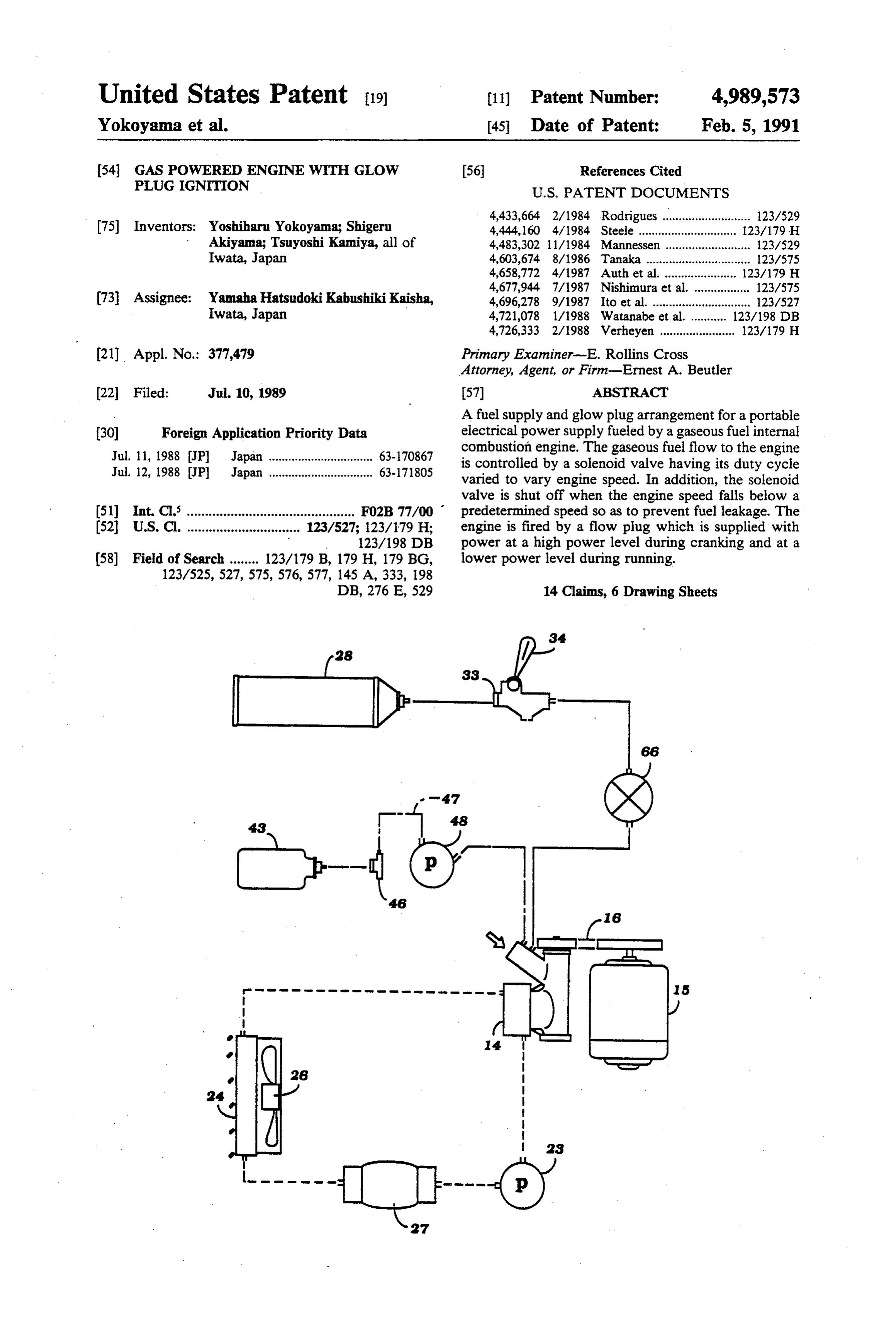
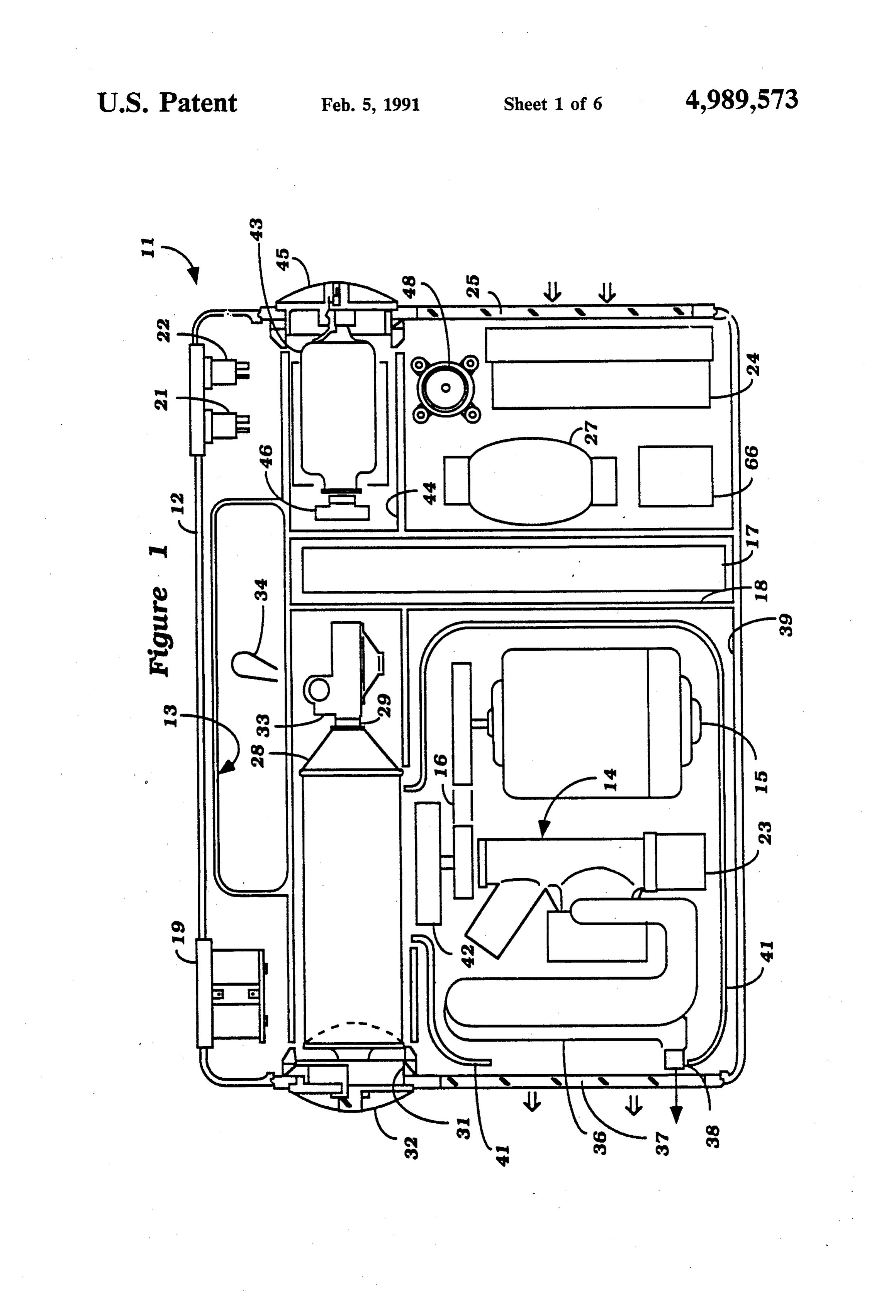
BACKGROUND OF THE INVENTION 5 FIG. 1 is a cross-sectional view taken through a por This invention relates to a gas powered engine with table power supply constructed in accordance with an glow plug ignition and more particularly to an im embodiment of the invention.
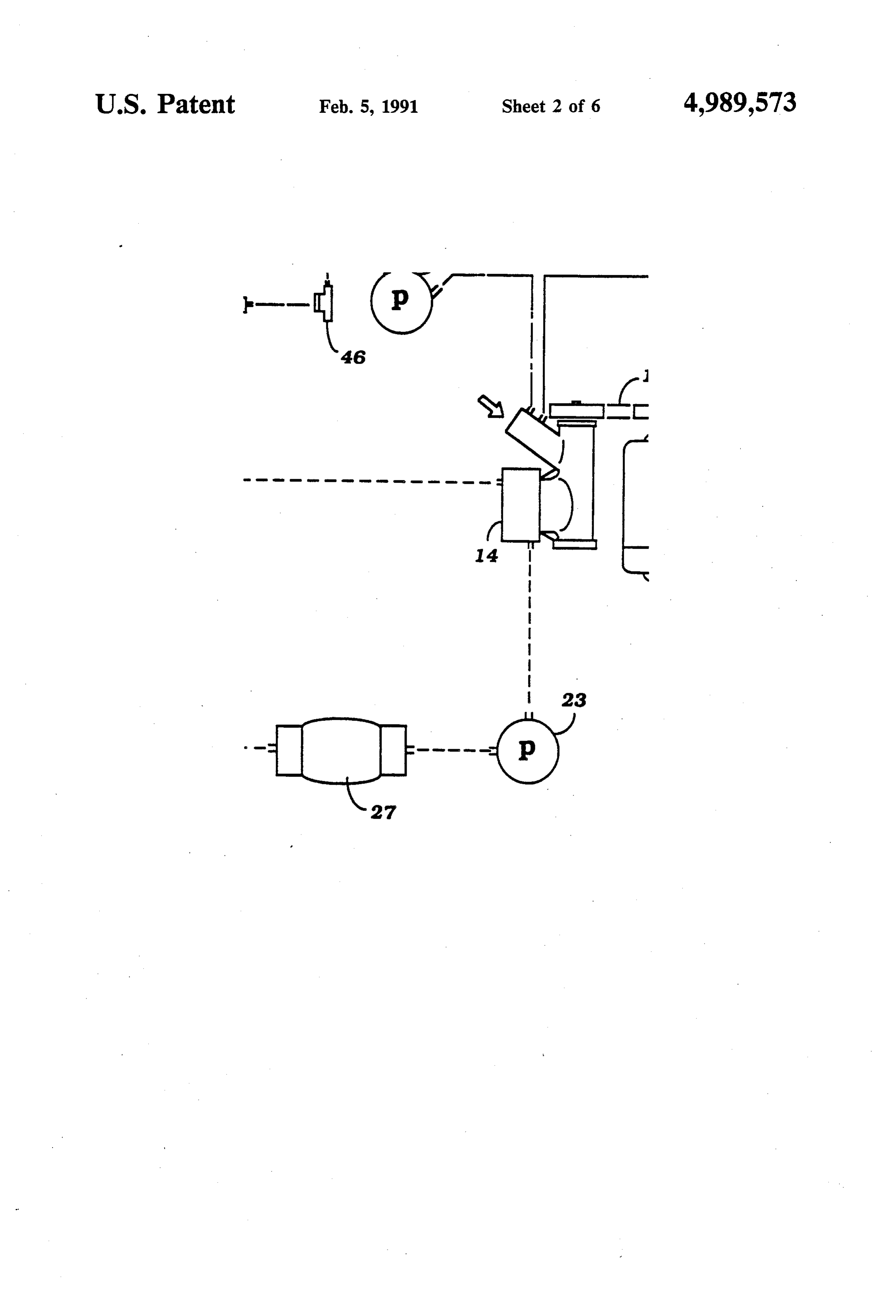
proved arrangement for controlling the flow of gas to FIG. 2 is a partially schematic view showing the the engine and the heating of its glow plug. components of the power suppy and their interrelation There is a wide application for small internal combus 10 ship.
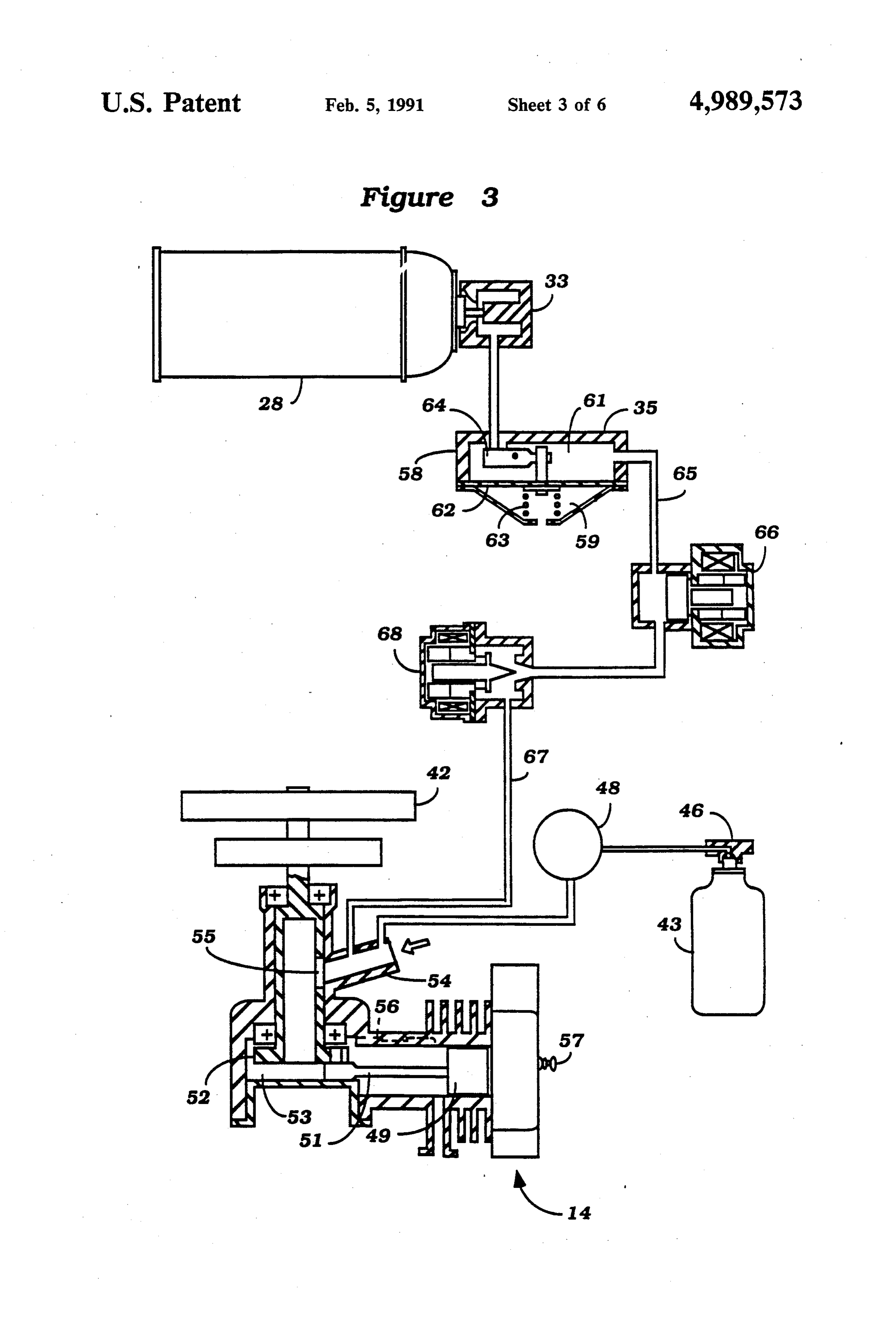
tion engines that are powered by gaseous fuel (LPG). FIG. 3 is a schematic view, in part similar to FIG. 2, Such engines may be utilized for a wide variety of pur with portions shown in cross-section and shows more poses, for example, for small electrical powered genera details of the fuel feed system and lubricant feed system tors. The use of gaseous fuel has a number of advantages 5 for the engine.
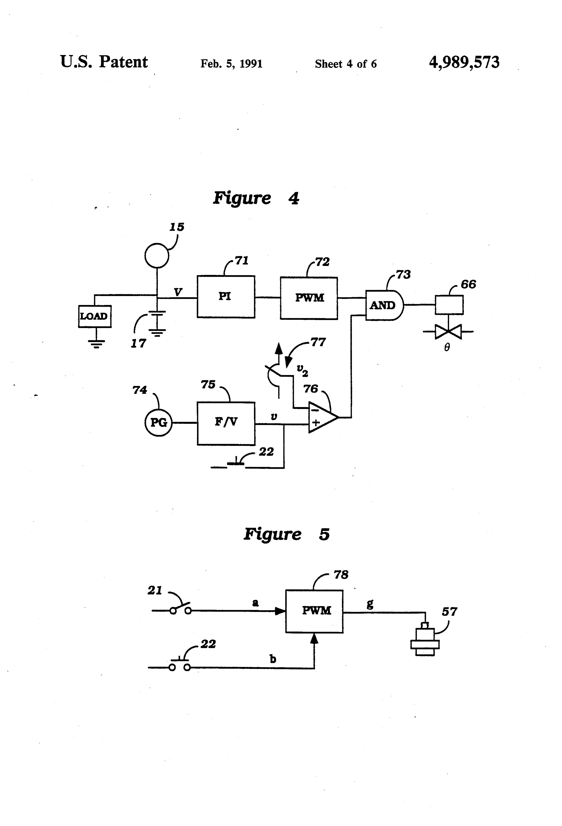
but also presents certain difficulties. For example, it is FIG. 4 is a diagrammatic view showing the control one practice to supply the fuel to the engine at approxi circuit for the fuel controlling solenoid. mately atmospheric pressure. The fuel is then drawn FIG. 5 is a schematic view showing the arrangement into the engine through the negative pressure that exists for controlling the glow plug.
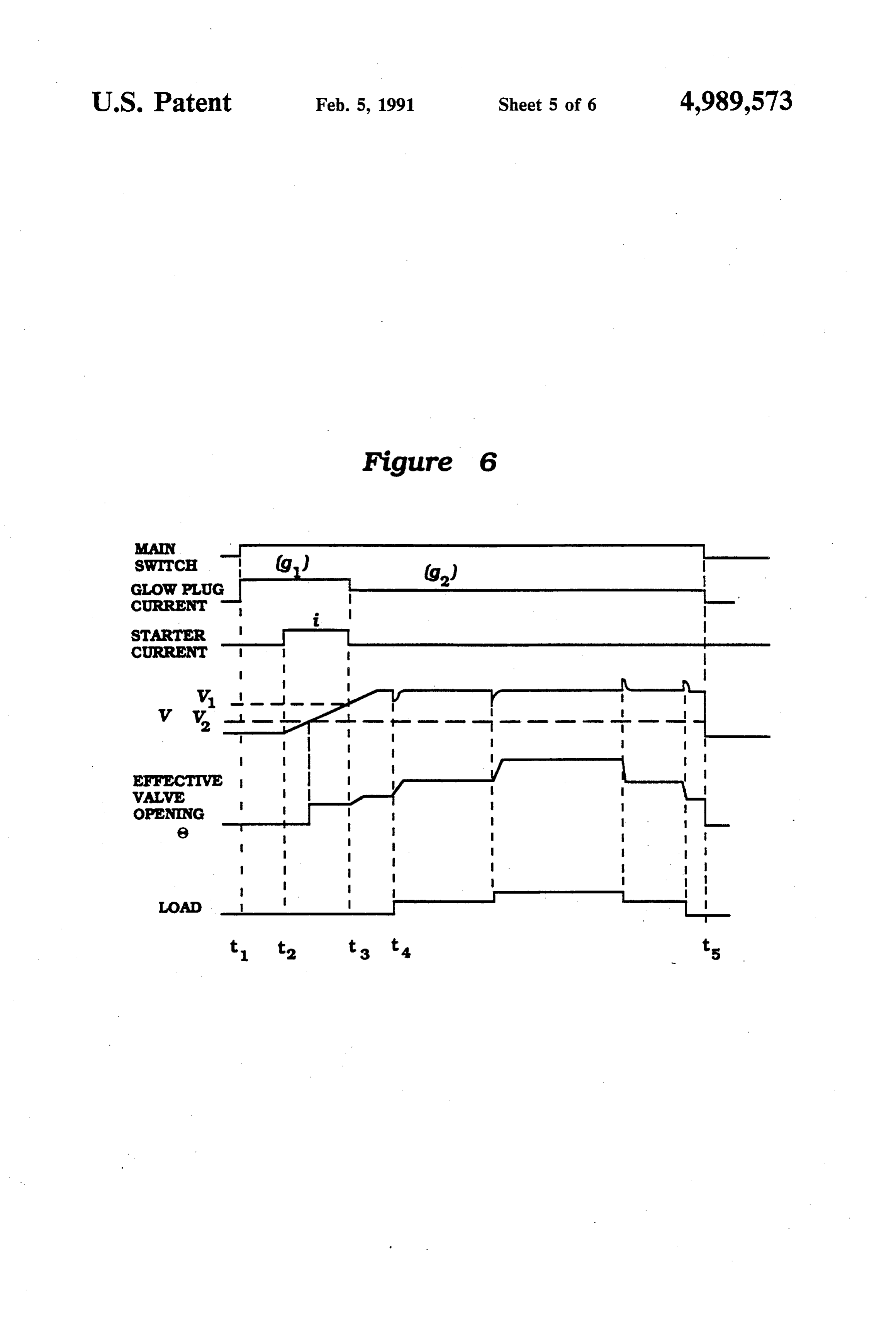
in the induction system on the intake stroke. Although FIG. 6 is a graphical view showing the various con this arrangement has some advantages, it also may not 20 trol conditions during certain phases of engine opera always insure that an appropriate amount of fuel is tion.
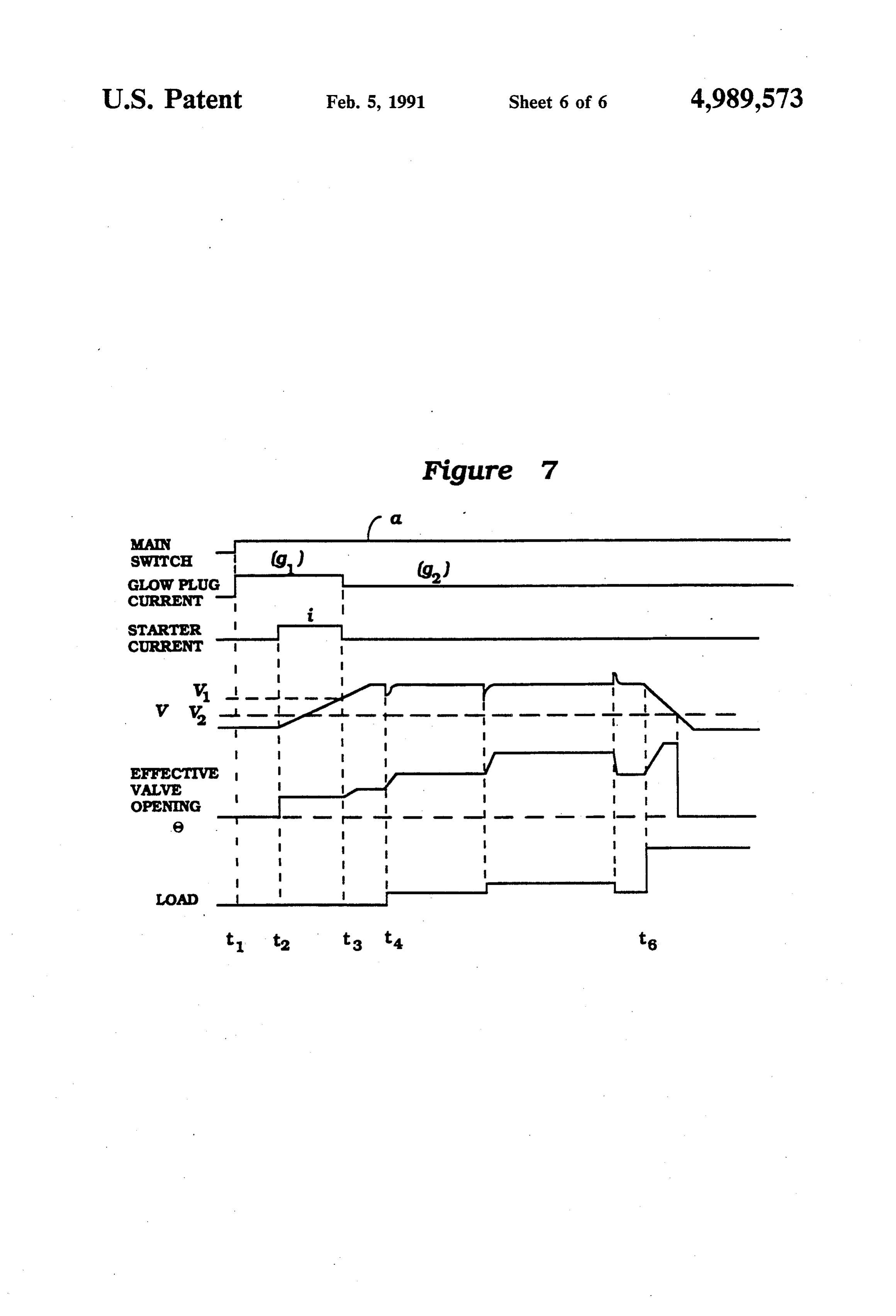
inducted into the engine for its smooth running. FIG. 7 is a graphical view, in part similar to FIG. 6, In order to avoid the aforenoted difficulties, there are and shows other phases of engine operation. advantages if the fuel is supplied to the engine at a 25 DETAILED DESCRIPTION OF THE slightly than greater atmospheric pressure. For exam PREFERRED EMBODIMENT ple, if the fuel is supplied at relatively low gauge pres sure (such as 0.04 kg/cm2) then the engine may operate Referring first primarily to FIGS. 1 and 2, a compact more satisfactorily. However, when the engine is portable electric power supply constructed in accor Stopped or slowed significantly, this greater than atmo 30 dance with an embodiment of the invention is identified spheric fuel pressure may cause excess fuel consump generally by the reference numeral 11. The invention is tion. described in conjunction with a portable power supply It is, therefore, a principal object of this invention to since such devices advantageously run on LPG fuel. provide an improved gaseous fuel supplying system for However, it is to be understood that the invention can an internal combustion engine. 35 be utilized in other applications wherein an internal It is a further object of this invention to provide a combustion engine is supplied with a liquefied gaseous gaseous fuel supply system for an internal combustion fuel and the fuel is supplied to the engine in gaseous engine that operates at greater than atmospheric pres form.
sures and which will insure that the supply of fuel is The power unit 11 is comprised of an outer housing, discontinued when the engine stops or slows below a indicated generally by the reference numeral 12, and certain speed. which contains all of the components of the power In order to maintain simplicity for the engines oper supply. The outer housing 12 may be formed from any ated on gaseous fuel, it is practical to employ a glow suitable material such as a molded plastic and is formed plug for cold starting. Although glow plugs are effec with a carrying handle 13 formed by an opening at its tive in cold starting, it may be necessary with gaseous 45 upper end.
fuels to provide an additional amount of heat to the Contained with the outer housing 12 is a single cylin glow plug even during engine running. This will insure der, liquid cooled, small displacement internal combus good combustion. However, if the glow plug is applied tion engine, indicated generally by the reference nu with the same current or heat during running as during meral 14. In the illustrated embodiment, the engine 14 is starting, its life will seriously deteriorate. 50 operated under the two-stroke, crankcase compression It is, therefore, a still further object of this invention principle, however, it should be readily apparent to to provide an improved glow plug and control arrange those skilled in the art that the engine 14 may be a four ment for an internal combustion engine. stroke cycle engine and may have other than a single SUMMARY OF THE INVENTION cylinder and, in fact, may be a rotary or other type of 55 engine than a reciprocating engine.
A first feature of this invention is adapted to be em The engine 14 has its output shaft connected to a shaft bodied in a fuel supply circuit for a gas powered inter of a combined starter and generator 15 by means of a nal combustion engine comprising a source of pressur driving belt 16. The starter, generator 15 is coupled ized gaseous fuel. Conduit means supply fuel from the with an electrical circuit that includes a vertically posi Source to the engine and means are provided for discon tioned battery 17 contained within a compartment 18 tinuing the supply of fuel from the source to the engine formed by the outer housing 12. This circuit permits the when the speed of the engine falls below a predeter starter, generator 15 to operate as a starter so as to start mined value. the engine 14. Once the engine 14 commences running, Another feature of the invention is also adapted to be the starter, generator 15 will operate as a generator and embodied in an internal combustion engine having a 65 supply a charge to the battery 17 and also provide an glow plug ignition system. In accordance with this electrical output to a receptacle 19 carried adjacent the feature of the invention, the glow plug is provided with handle 13 so as to permit an electrical device to be a higher degree of power during starting and the power plugged in and powered by the unit 11.
Page 9
There is provided adjacent the handle 13 on the side 43 to the engine 14. The pump 48 also meters a very opposite the receptacle 19 a main control switch 21 for small amount of lubricant so as to insure very good switching the power on and off and a starter switch 22 lubrication for the engine under all running conditions for operating the starter, generator 15 in its starter and to avoid excess lubricant flow and consumption. mode. 5 FIG. 3 shows in more detail the fuel supply system The engine 14 is further provided with a cooling for the engine 14 and also some details of the construc System that includes a coolant pump 23 that is driven by tion of the engine 14. Referring now to this figure, it the engine 14 and which circulates coolant through a will be seen that the engine 14 is of the single cylinder, cooling jacket of the engine and a heat exchanging crankcase compression type and includes a single recip radiator 24. The radiator 24 is juxtaposed to an air inlet 10 rocating piston 49 that is connected by means of a con opening 25 formed at one side of the housing 12. There necting rod 51 to a crankshaft 52. The engine is pro is further provided an electric fan 26 that is powered by vided with a crankcase chamber 53 to which a fuel/air the battery 17 and which circulates the air across the charge is introduced by means of an air inlet passage core of the radiator 24. The cooling system also in way 54 that communicates with the crankcase chamber cludes an accumulator type pressure control device 27 15 53 by means of a rotary valve 55. The fuel/air which is which is comprised generally of a expansible hose sec delivered to the crankcase chamber 53 is transferred to tion so as to compensate for volume differences in the the area above the head of the piston 49 through a trans coolant of the engine 14 as occur during engine opera fer or scavenge passage 56 for combustion. During cold tol.
The engine 14 is fueled by a pressurized source of 20 starting,
this combustion is initiated by means of a glow that is supported in the cylinder head of the gaseous fuel (LPG) that is contained within a remov engine and which is powered in a known manner. The able container 28 that is detachably connected to a glow plug 57 is continuously operated after the engine receptacle 29 immediately beneath the handle portion has started but at a reduced current so as to prolong the 13. The container 28 is placed into the receptacle 29 through an opening 31 formed at one side of the housing 25 life of the glow plug 57, this being accomplished in a 12 and which opening is normally closed by a closure manner Referring to be described.
now specifically to the fuel delivery sys plug 32.
The receptacle 29 is coupled to a main shutoff valve tem, it should be noted that the fuel pressure regulator 33 having a control handle 34 so as to permit the supply 35 is comprised of an outer housing 58 that is divided into an atmospheric chamber 59 and a fuel pressure of fuel from the container 28 to be shut off from the remainder of the fuel supply circuit for the engine when chamber 61 by means of a diaphragm 62. The dia the power supply 11 is not being utilized. phragm 62 is also biased by means of a spring 63 con A conduit connects the main shutoff valve 33 with a tained within the atmospheric chamber 59 and operates duty solenoid valve 35 which controls the flow of fuel a valve element 64 so as to maintain a constant gas to the induction system of the engine 14 in a manner to 35 pressure to a conduit 65. The conduit 65 has positioned be described. within it a solenoid operated valve 66, which is cycled The engine 14 further includes an exhaust system that in a manner to be described, so as to provide a variable is comprised of a muffler 36 that is juxtaposed to an air fuel flow to the engine to maintain the desired constant outlet opening 37 which is formed at the side of the speed or output of the generator 15. A conduit 67 inter housing 12 opposite to the inlet opening 25. Air which connects the solenoid valve 66 with the intake passage has passed across the engine will then exit from the air way 54 and it will be noted that there is no throttle outlet opening 37 so as to cool the muffler 36. The valve in the intake passageway 54. Therefore, the speed muffler 36 also has a discharge opening 38 which regis of the engine 14 is controlled by varying the duty cycle ters with the opening 37 for discharge of exhaust gases of the solenoid valve 66 in a manner as will be de from within the housing 12. 45 scribed.
The engine 14 and generator 15 are contained within In addition, a further throttle valve 68 is provided in a main cavity 39 formed by the outer housing 22 and are the conduit 67 and is solenoid operated so as to provide surrounded by a protective shield 41 for further heat further fuel control depending upon the density of the insulation and ducting. An engine driven fan 42 circu fuel so as to insure against an overly rich mixture under lates air from within the housing 12 across the engine 50 Some running conditions. This is primarily operative at 14, muffler 36 and out the opening 37. low engine speeds so as to control prevent against too The engine 14 is also provided with a lubricating rich a mixture being generated in the induction system. system that receives lubricant from a separate lubricant It should also be noted that the fuel pressure regulator container 43 that is received within a compartment 44 35 maintains a slightly greater than atmospheric fuel formed in the outer housing 12 and which is closed by 55 pressure.
a removable closure plug 45. The lubricant container 43 The lubricant from the reservoir 43 is also discharged is of the cartridge type and is connected to a receiver 46 into the intake passageway 54 for lubrication of the that supplies lubricant to the engine induction system engine in a known manner.
through a conduit, shown schematically at 47 and in Referring now in detail to FIGS. 4, 6 and 7, the which a lubricant control pump 48 is positioned having 60 method by which the valve 66 is controlled so as to a construction as described in copending application vary the fuel flow and maintain the desired engine speed entitled "Compact Power Supply And Lubricant Af and/or output of the generator 15 will be described. In fording Device Therefore', Ser. No. 377,480, filed July addition, the operation of the starter motor and glow 10, 1989, and assigned to the assignee of this application. plug 57 will also be described by reference to these The lubricant pump 48 is designed so as to provide a 65 FIGS. 5, 6 and 7. The generator 15 produces a voltage positive flow of lubricant and also will in effect close V that varies with the load on the circuit. This voltage the conduit 47 when the engine is not running so that signal V is inputted to a fuel supply controller 71 that lubricant cannot inadvertently flow from the reservoir varies the fuel supplied to the engine by outputting a
Page 10
signal to a pulse width modulator 72 that varies the duty has been noted, this prolongs the life of the glow plug cycle of the solenoid 66. 57.
The construction as thus far described, however, will When the starter current was energized at the point mean that if the engine speed slows below its normal t2, the valve 66 was then begun on its duty cycle and speed and below a speed at which it can continue to run, was opened to the starting condition. When the starter fuel nevertheless will be supplied to the engine in in current was discontinued at the point t3, the effective creasing quantities. Therefore, the device also incorpo valve opening 0 was continued to increase and will rates an arrangement which insures that this condition increase until the engine speed reaches it desired speed. cannot prevail. To this end, there is provided in the This occurs some time after the point t3. circuit connecting the pulse width modulator 72 with 10 During the engine running, if the load on the engine the solenoid valve 66 and AND gate 73 which must be increases, as at the point ta, the engine will tend to slow turned on in order for the pulse width modulation signal down and the voltage signal V will decrease. When this from the modulator 72 to operate the valve 66. happens, the controller 71 increases the output for the The AND gate is switched on and off by a circuit that 15 pulse width modulator 72 so as to increase the duty includes a pulse generator 74 that generates pulses dur cycle of the solenoid valve 66 so as to maintain the ing rotation of the engine output shaft and outputs them constant engine speed. At subsequent load increases, the to a frequency-to-voltage converter 75 which outputs a same will happen. In a like manner, if the load de voltage signal V indicative of engine speed. creases, the voltage signal V will increase and the duty The output voltage V is compared in a comparator 76 20 cycle of the solenoid valve 66 is decreased by the con with a reference voltage set by a settable device 77. The troller 72 so as to maintain speed. At a point when the set voltage signal v2 is a speed normally below that at main switch is turned off t5, the glow current will be discontinued and the valve 66 will be shut off so as to which the engine can continue to run by itself. As long stop the engine.
as the speed of the engine is above this speed, the con
Under parator 75 will be turned on and the AND gate 73 will on the engine certain circumstances, it may be that the load be conductive so as to permit the control of the solenoid 25 at is so great that the engine might stall and, this time with valve 66. If, however, the speed falls below the speed noted, the fuel flow a conventional arrangement, as afore v2, then the AND gate 73 will be shut off and the sole lem. could continue and cause a prob noid valve 63 will be switched off. FIG. 7 shows another series of conditions that are Because of the incorporation of the AND gate 73 and 30 similar to the conditions of FIG. 5 but, in these condi the speed control circuit for switching the AND gate increase isin noted tions, it load at the point in time to that an abrupt occurs on the engine which tends to on and off, it is also necessary to provide a high voltage cause it to slow significantly. During the initial phase signal to the comparator 76 during starting so that the until the engine speed falls below the speed v2 set by the engine will be supplied with starting fuel. For that rea setting device 77 previously referred to, the fuel supply son, the starter switch 22 is also in circuit with the plus 35 to the engine will increase. However, as soon as the terminal of the comparator 76 so that when the starter speed reaches the speed v2, the comparator 76 will switch 22 is closed, the AND gate 73 will always be cease outputting a signal and the AND gate 73 will be conductive. turned off so as to shut off the solenoid valve 66 and FIG. 5 shows how the glow plug 57 is operated so as discontinue the supply of fuel to the engine. In this way, to provide a high power input to it during starting and the loss of fuel under this condition is avoided and the a lower power input during normal running. To this engine will be stopped and must be restarted after the purpose, the main switch 21 and starter switch 22 are load has been removed.
connected to a controller 78 which outputs power to It should be readily apparent from the foregoing the glow plug 57 so as to operate it. When the output of description that the arrangement is very effective in both the main switch 21 (a) and starter switch 22 (b) are 45 insuring adequate fuel for the engine and also while inputted to the controller 78, a high power output gi insuring that fuel will not be inadvertently lost in the will be outputted to the glow plug 51. However, when event that the engine is shut off or a load which tends to only the main switch 21 is closed, a lower power g2 will cause stalling of the engine is applied. In addition, the be outputted to the glow plug 57. glow plug is supplied with sufficient power to provide Referring now to FIG. 6, the effective valve opening 50 adequate heating for starting but the power level to the 0 of the solenoid valve 66 is depicted in relation to load glow plug is reduced during engine running. Although and operation of the starter main switch and starter. In an embodiment of the invention has been illustrated and addition, the current supplied to the glow plug 57 is also described, various changes and modifications may be depicted. When the main switch 21 is turned on and the made without departing from the spirit and scope of the starter switch 22 is energized at the point t1, the main 55 invention, as defined by the appended claims. switch current will rise to the on level as shown and the We claim:
glow plug will be supplied with current at an elevated 1. In a fuel supply circuit for a gas powered internal level g1 so as to provide the necessary heat for starting. combustion engine comprising a source of pressurized After a certain time delay as indicated by the point t2, gaseous fuel, conduit means for supplying fuel from said the current to the starter 15 will be raised to the level i course to said engine, valve means for regulating the and the engine will be cranked. The cranking speed amount of fuel supplied to said engine for controlling continues until the speed reaches the speed indicated by the speed of said engine without throttling the air flow the voltage v1 at the point in time t3. At this time, it is to said engine and means for deactivating said valve determined that the engine is running and the starter, means for discontinuing the supply of fuel from said generator 15 then converts to a generator output and 65 source to said engine when the speed of said engine falls the current to the starter is discontinued. At this same below a predetermined value.
time, the glow plug current is reduced to a lower level 2. In a fuel supply circuit as set forth in claim 1 g2 and the glow plug will be heated at a slower rate. As wherein the valve means comprised of solenoid oper
Page 11
ated valve interposed in the conduit means for control the glow plug during starting and a second lower power ling the amount of fuel supplied to the engine for main to the glow plug during running. taining a constant engine speed. 9. In a fuel supply circuit as set forth in claim 1 3. In a fuel supply circuit as set forth in claim 2 wherein an electrical generator is driven by the engine wherein the means for discontinuing the supply of fuel and the speed of the engine is determined by the output to the engine includes means for shutting off the sole of the generator.
noid valve. 10. In a fuel supply circuit as set forth claim 2 wherein 4. In a fuel supply circuit as set forth in claim 1 fur- . an electrical generator is driven by the engine and the speed of the engine is determined by the output of the ther including pressure regulating means between the O generator.
source of pressurized gaseous fuel and the conduit leaS. 11. In a fuel supply circuit as set forth claim 7 further 5. In a fuel supply circuit as set forth in claim 4 the runninga generator including condition driven by the engine and wherein of the engine is determined by the wherein the valve means comprises a solenoid operated output of the generator.
valve means interposed in the conduit means for con 15 12. In a fuel supply circuit as set forth claim 8 further trolling the amount of fuel supplied to the engine for including a generator driven by the engine and wherein maintaining a constant engine speed. the running condition of the engine is determined by the 6. In a fuel supply circuit as set forth in claim 5 output of the generator.
wherein the means for discontinuing the supply of fuel 13. In an internal combustion engine having a com to the engine includes means for shutting off the sole bustion chamber, a glow plug extending into said com noid valve. bustion chamber, a generator driven by said engine, a 7. In a fuel supply circuit as set forth in claim 6 fur means responsive to the output of said generator for ther including a glow plug for firing a charge in the supplying power to said glow plug at a higher annount engine and means for supplying a first higher power to during starting and at a lower amount during running as the glow plug during starting and a second lower power 25 determined by the output of said generator. to the glow plug during running. 14. In an internal combustion engine as set forth in 8. In a fuel supply circuit as set forth in claim 1 fur claim 13 wherein the engine is operated by a gaseous ther including a glow plug for firing a charge in the fuel.
engine and means for supplying a first higher power to : 2k ck :
Provenance
- Collection
- Cited prior art
- Original PDF
- patentimages.storage.googleapis.com →
- Filed
- 1989-07-10
- Pages
- 11
- Method
- pdftotext (the PDF's own text layer) + pdftoppm 300dpi page scans
- Source
- Google Patents bibliographic record
- Granted
- 1991-02-05
- Inventors
- Yoshiharu Yokoyama; Shigeru Akiyama; Tsuyoshi Kamiya; Yamaha Motor Co Ltd
- Transcribed from
- patentimages.storage.googleapis.com →