patent · US3446313
Apparatus for preventing the inlet valve wear of supercharged internal combustion engines
27 May 1969
Page 1
Drawing sheet — no readable text.
Page 2
United States Patent Office 3,446,313 Patented May 27, 1969
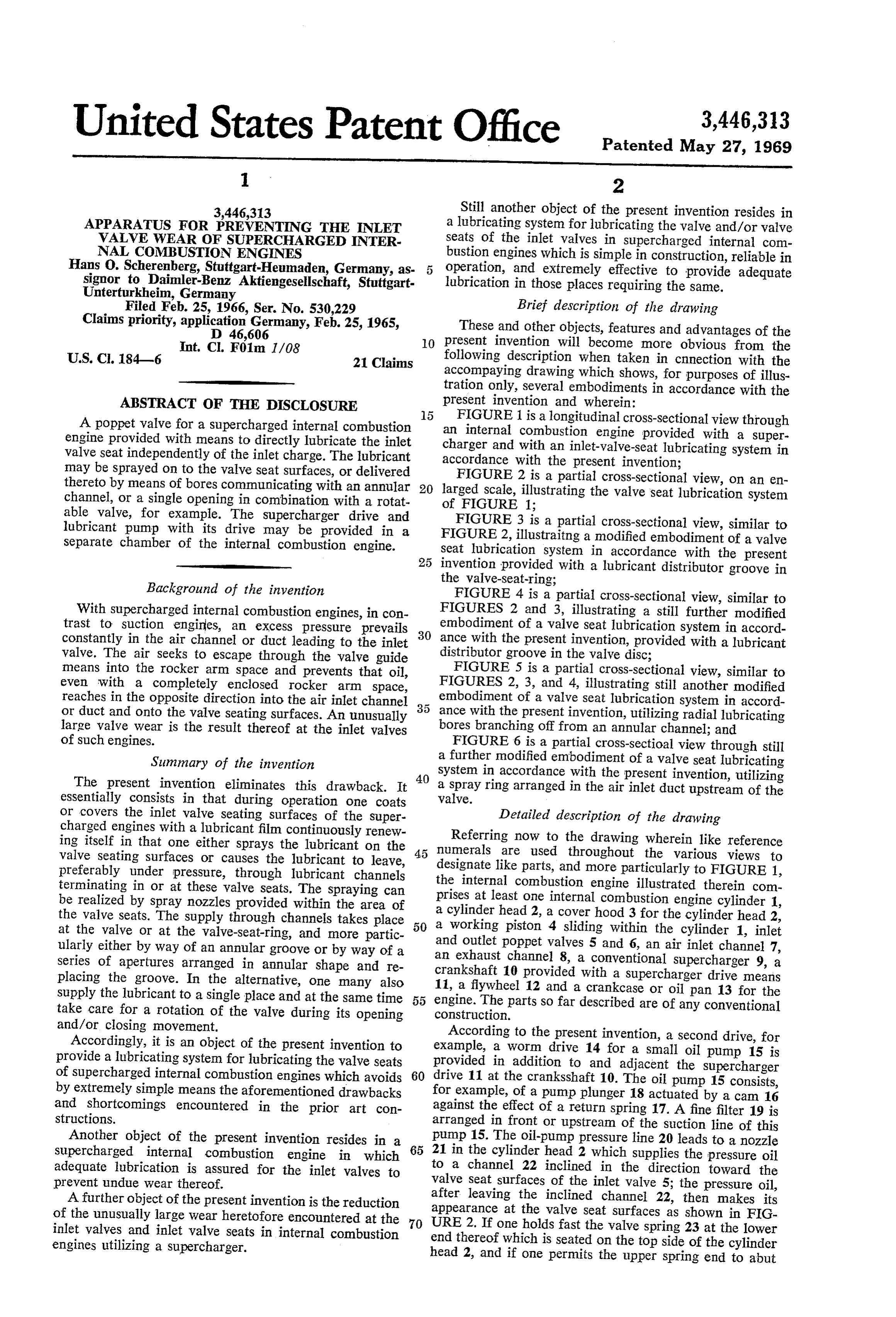
3,446,313 Still another object of the present invention resides in APPARATUS FOR PREVENTING THE INLET a lubricating system for lubricating the valve and/or valve VALVE WEAR OF SUPERCHARGED INTER seats of the inlet valves in supercharged internal com NAL COMBUSTION ENGINES bustion engines which is simple in construction, reliable in Hans O. Scherenberg, Stuttgart-Heumaden, Germany, as 5 operation, and extremely effective to provide adequate signor to Daimler-Benz Aktiengesellschaft, Stuttgart lubrication in those places requiring the same. Unterturkheim, Germany
Filed Feb. 25, 1966, Ser. No. 530,229 Brief description of the drawing Claims priority, application Germany, Feb. 25, 1965, These and other objects, features and advantages of the D 46,606 O present invention will become more obvious from the
U.S. Cl. 184—6 21 Claims following description when taken in cnnection with the accompaying drawing which shows, for purposes of illus tration only, several embodiments in accordance with the
ABSTRACT OF THE DISCLOSURE present invention and wherein:
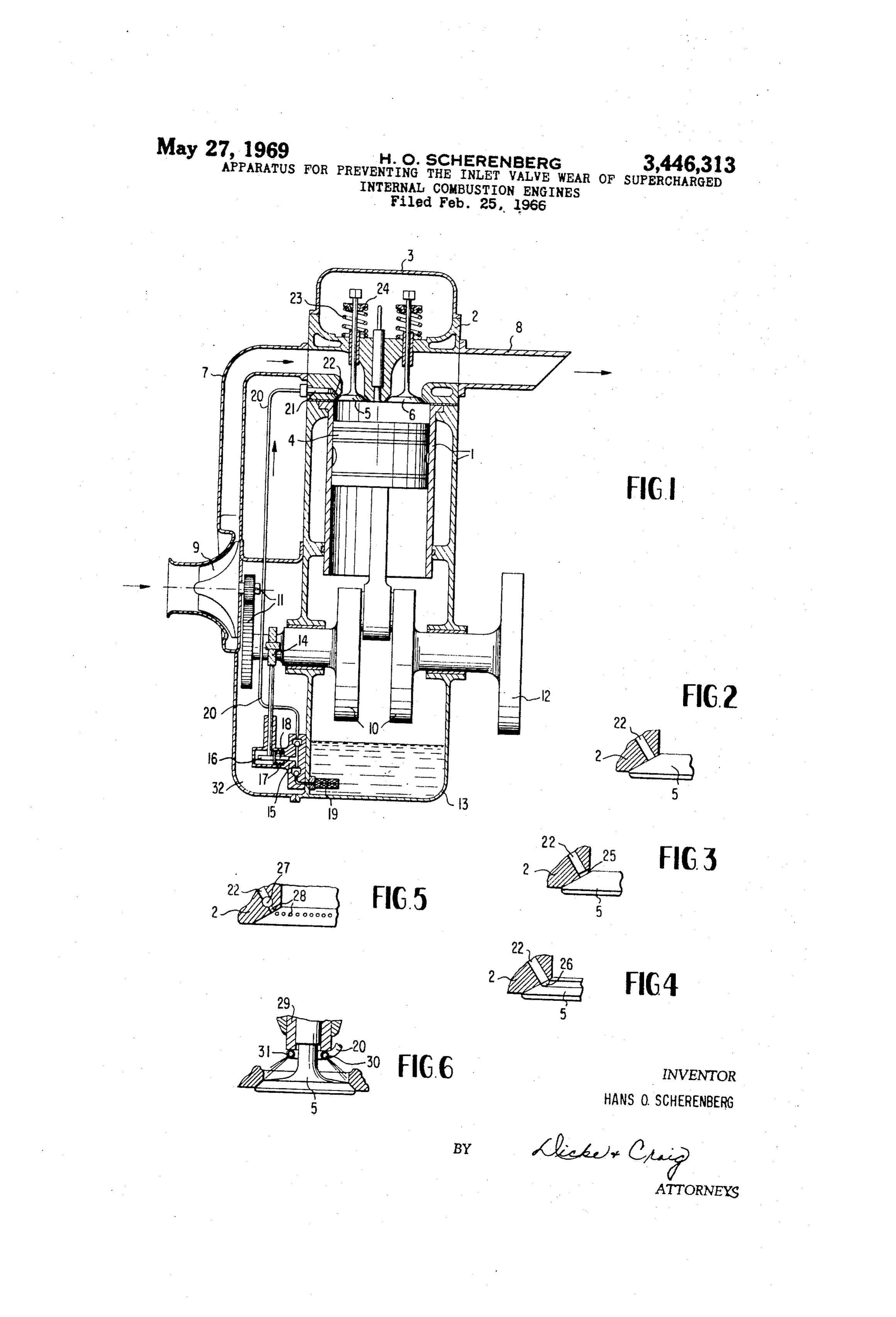
A poppet valve for a supercharged internal combustion anFIGURE 1 is a longitudinal cross-sectional view through
engine provided with means to directly lubricate the inlet internal combustion engine provided with a super valve seat independently of the inlet charge. The lubricant charger and with an inlet-valve-seat lubricating system in may be sprayed on to the valve seat surfaces, or delivered accordance with the present invention; thereto by means of bores communicating with an annular 20 larged scale,2illustrating
FIGURE is a partial cross-sectional view, on an en the valve seat lubrication system channel, or a single opening in combination with a rotat of FIGURE 1;
able valve, for example. The Supercharger drive and FIGURE 3 is a partial cross-sectional view, similar to lubricant pump with its drive may be provided in a FIGURE 2, illustraitng a modified embodiment of a valve separate chamber of the internal combustion engine. seat lubrication system in accordance with the present 25 invention provided with a lubricant distributor groove in the valve-seat-ring;
Background of the invention FIGURE 4 is a partial cross-sectional view, similar to With supercharged internal combustion engines, in con FIGURES 2 and 3, illustrating a still further modified trast to suction engines, an excess pressure prevails embodiment of a valve seat lubrication system in accord constantly in the air channel or duct leading to the inlet 30 ance with the present invention, provided with a lubricant valve. The air seeks to escape through the valve guide distributor groove in the valve disc;
means into the rocker arm space and prevents that oil, FIGURE 5 is a partial cross-sectional view, similar to even with a completely enclosed rocker arm space, FIGURES 2, 3, and 4, illustrating still another modified reaches in the opposite direction into the air inlet channel embodiment of a valve seat lubrication system in accord or duct and onto the valve seating surfaces. An unusually 35 ance with the present invention, utilizing radial lubricating large valve wear is the result thereof at the inlet valves bores branching off from an annular channel; and of such engines. FIGURE 6 is a partial cross-sectioal view through still Summary of the invention a further modified embodiment of a valve seat lubricating system in accordance with the present invention, utilizing
The present invention eliminates this drawback. It 40 a spray ring arranged in the air inlet duct upstream of the essentially consists in that during operation one coats valve.
or covers the inlet valve seating surfaces of the Super Detailed description of the drawing charged engines with a lubricant film continuously renew Referring now to the drawing wherein like reference ing itself in that one either sprays the lubricant on the numerals are used throughout the various views to valve seating surfaces or causes the lubricant to leave, 45 designate like parts, and more particularly to FIGURE 1, preferably under pressure, through lubricant channels terminating in or at these valve seats. The spraying can the internal combustion engine illustrated therein com be realized by spray nozzles provided within the area of prises at least one internal combustion engine cylinder 1, the valve seats. The supply through channels takes place 50 aa cylinder head 2, a cover hood 3 for the cylinder head 2, working piston 4 sliding within the cylinder 1, inlet at the valve or at the valve-seat-ring, and more partic ularly either by way of an annular groove or by way of a and outlet poppet valves 5 and 6, an air inlet channel 7, series of apertures arranged in annular shape and re crankshaft an exhaust channel 8, a conventional supercharger 9, a placing the groove. In the alternative, one many also 11, a flywheel 10 provided with a supercharger drive means supply the lubricant to a single place and at the same time 55 engine. 12 and a crankcase or oil pan 13 for the take care for a rotation of the valve during its opening construction. so far described are of any conventional The parts and/or closing movement. According to the present invention, a second drive, for Accordingly, it is an object of the present invention to example, provide a lubricating system for lubricating the valve seats provided ain worm drive 14 for a small oil pump 15 is addition to and adjacent the supercharger of supercharged internal combustion engines which avoids 60 drive 11 at the cranksshaft 10. The oil pump 15 consists, by extremely simple means the aforementioned drawbacks for example, of a pump plunger 18 actuated by a cam 16 and shortcomings encountered in the prior art con against the effect of a return spring 17. A fine filter 19 is structions. arranged in front or upstream of the suction line of this Another object of the present invention resides in a pump 15. The oil-pump pressure line 20 leads to a nozzle supercharged internal combustion engine in which 65 21 in the cylinder head 2 which supplies the pressure oil adequate lubrication is assured for the inlet valves to to a channel 22 inclined in the direction toward the prevent undue wear thereof. valve seat surfaces of the inlet valve 5; the pressure oil, A further object of the present invention is the reduction after leaving the inclined channel 22, then makes its of the unusually large wear heretofore encountered at the 70 appearance at the valve seat surfaces as shown in FIG URE 2, If one holds fast the valve spring 23 at the lower inlet valves and inlet valve seats in internal combustion engines utilizing a Supercharger. end thereof which is seated on the top side of the cylinder head 2, and if one permits the upper spring end to abut
Page 3
3 7. The combination according to claim 1, wherein said freely against the spring disc 24 of the valve stem, then second means supplies engine lubricant to said first means. the valve carries out a slight rotation as a result of the 8. The combination according to claim 1, wherein the stressing of the spring occurring during its opening move engine includes an oil sump and a crankshaft, and wherein ment with the consequence that in due time the entire seating surface at the valve disc moves past the bore 22 and said Second means includes an oil pump driven by said is thereby wetting with oil that, in turn, also reaches there crankshaftmeans.
and provided with a pressure line leading to by the counter-seating surfaces of the valve seat. How said9. first The combination according to claim 8, wherein said ever, any other known means for rotating the valve during first means includes annular groove means distributing the its opening and/or closing movement may be provided in lieu thereof. 10 lubricant and provided in the seat surfaces of one of the Furthermore, within the scope of the present invention, two partstheconsisting of the valve seat ring and of the valve one may take care beforehand for an intensive distribution disc10.ofThe inlet valve.
of the lubricant at the seating surfaces in that one provides, first meanscombination according to claim 8, wherein said for example, according to FIGURE 3, an annular groove large numberincludes an annular channel and, a relatively of radial bores branching off from said an 25 at the valve seat ring of the cylinder head 2, or accord 15 ing to FIGURE 4, an annular groove 26 for the reception nular channel and terminating at the seat surfaces, and and distribution of the lubricant at the valve disc. wherein said lubricant pressure line terminates in said an In the embodiment according to FIGURE 6, the pres nular channel.
sure oil line 22 terminates in an annular channel 27 sur 11. The combination according to claim 8, wherein said rounding the valve seat from which a series of fine 20 first means includes injection nozzle means located at a lubricant bores 28 terminate at the valve seat Surfaces. distance upstream of the inlet valves, said lubricant pres In the embodiment acocrding to FIGURE 6, the pres Sure line terminating in said injection nozzle means. sure oil line 20 terminates directly above the valve seat 12. The combination according to claim 11, wherein surfaces, for example, below the valve plunger guide bush 25 said injection nozzle means includes at least one nozzle ing 29 in a single spray nozzle 30 or in a spray ring 31 which injects the lubricant in one or several jets or also in directed against the valve seat surfaces. conical shape uniformly over the seating Surface the injectioncombination
nozzle means includes an injection ring pro circumference. vided with injection apertures directed against the seat The lubricant pump 15 together with its drive 14, 30 Surfaces.
16, 17, 18 is accommodated together with the Super 14. The combination according to claim 8, wherein the charger drive 11 in a separate chamber 32 disposed ad jacent the crankcase 13 of the internal combustion engine. the oil pump together with its drive means located between While I have shown and described several embodi crankshaft and the Supercharger drive means are ar ments in accordance with the present invention, it is under 35 ranged together with said supercharger drive means in a stood that the same is not limited thereto but is susceptible separate chamber of the internal combustion engine. of numerous changes and modifications as known to a 15. The combination according to claim 14, wherein person skilled in the art, and I therefore do not wish to the drive means for the lubricating pump includes worm be limited to the details shown and described herein but drive means which actuates by way of a can a pump intend to cover all such changes and modifications as are 40 plunger under the influence of a return spring. encompassed by the scope of the appended claims. 16. The combination according to claim 15, wherein I claim: said oil pump includes a suction line provided with fine 1. A lubricating system for lubricating the inlet valves of supercharged internal combustion engines equipped filter means.
17. The combination according to claim 8, wherein with poppet valves to minimize the wear thereof, com the drive means for the lubricating pump includes worm prising an inlet poppet valve having valve seat Surfaces, a supercharger for pressurizing the inlet charge, first means drive means which actuates by way of a cam a pump for effectively supplying a lubricant directly to the valve plunger
under the influence of a return spring.
The combination according to claim 8, wherein seat surfaces substantially independent of the inlet charge, said oil pump includes a suction line provided with fine and second means operatively connected with said first 50 filter means.
means for providing a supply of lubricant during operation 19. The combination according to claim 3, wherein of the engine. said second means supplies engine lubricant to said first 2. The combination according to claim 1, wherein said first means includes discharge means for spraying the lu leaS.
bricant against the valve seat Surfaces. 20. The combination according to claim 5, wherein said 3. The combination according to claim 1, wherein said second means supplies engine lubricant to said first means. first means includes lubricant channel means terminating 21. The combination according to claim 6, wherein said in the valve seat surfaces. second means supplies engine lubricant to said first means. 4. The combination according to claim 2, wherein said second means is operable to cause the lubricant to leave 60 References Cited said lubricant channels under pressure. UNITED STATES PATENTS 5. The combination according to claim 1, wherein said first means includes means for wetting the valve seat sur 2,526,450 10/1950 Aspin.
faces at least in one place with lubricant, and means for imparting a rotary movement to the inlet valve during 65 HOUSTON S. BELL, JR., Primary Examiner. reciprocating movements thereof. U.S. Cl. X.R. 6. The combination according to claim 1, wherein said 123-196 first means includes means uniformly distributing the lu bricant over the valve seat surfaces.
Provenance
- Collection
- Cited prior art
- Original PDF
- patentimages.storage.googleapis.com →
- Filed
- 1966-02-25
- Pages
- 3
- Method
- pdftotext (the PDF's own text layer) + pdftoppm 300dpi page scans
- Source
- Google Patents bibliographic record
- Granted
- 1969-05-27
- Inventors
- Hans O Scherenberg; Daimler Benz AG
- Transcribed from
- patentimages.storage.googleapis.com →