patent · US583104
System of generating and using hydrogen gas and electricity
25 May 1897
Page 1
Drawing sheet — no readable text.
Page 2
Drawing sheet — no readable text.
Page 3
UNITED STATES PATENT OFFICE.
LUTHER II. WATTLES, OF PROVIDENCE, RIIODE ISLAND, ASSIGNOR, BY
DIRECT AND MESNE ASSIGNMIENTS, OF THREE-FOURTIIS TO WILLIAM
B. SITERMAN, OF SAME PLACE, AND BYRON C. DAVIS, OF BROOKLYN,
NEW YORK.
SYSTEM OF GENERATING AND USNG HYDROGEN GAS AND ELECTRICTY,
SFECIFICATION forming part of Letters Patent No. 588,104, dated May 25, 1897. Application filed December 7, 1895, Serial No. 571,336, (No model.)
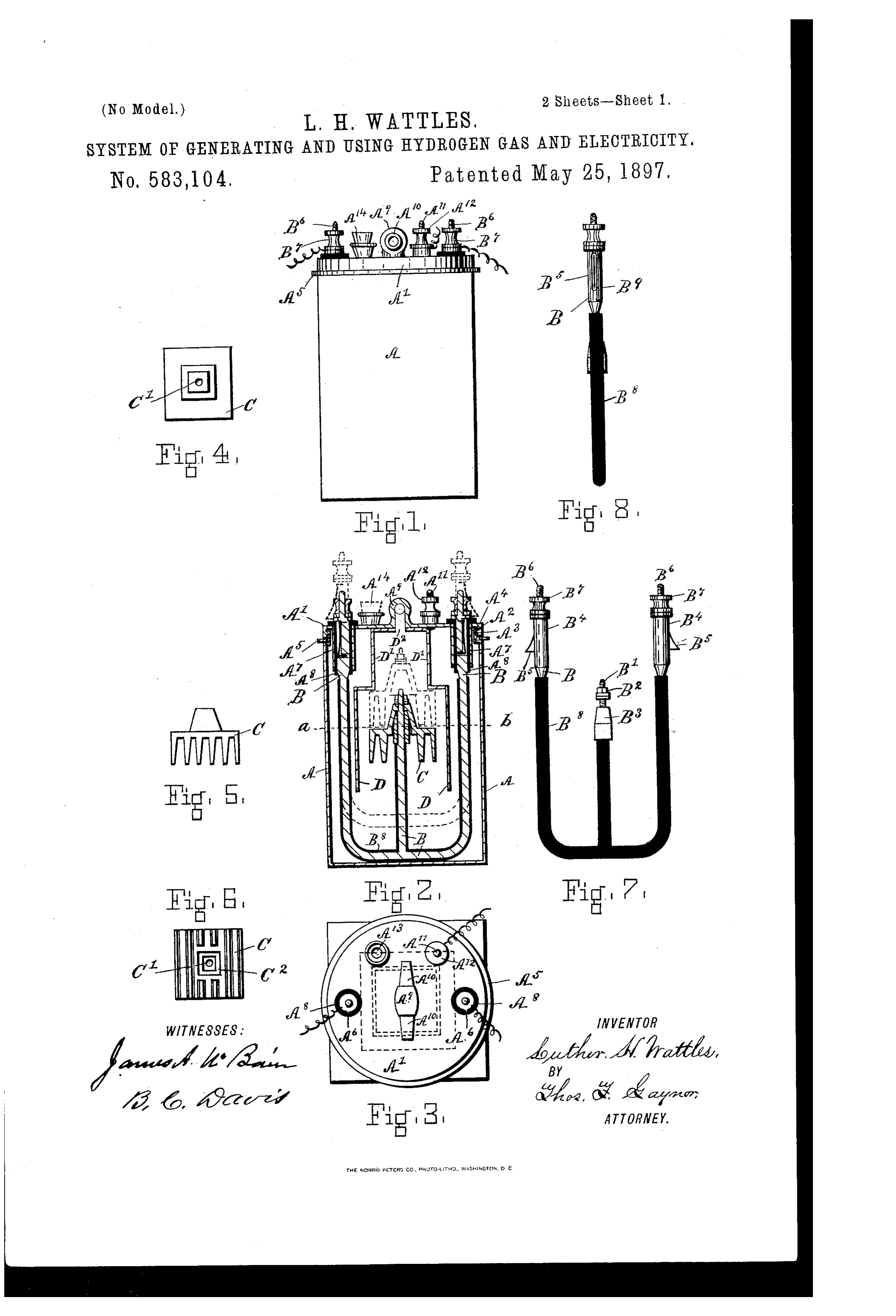
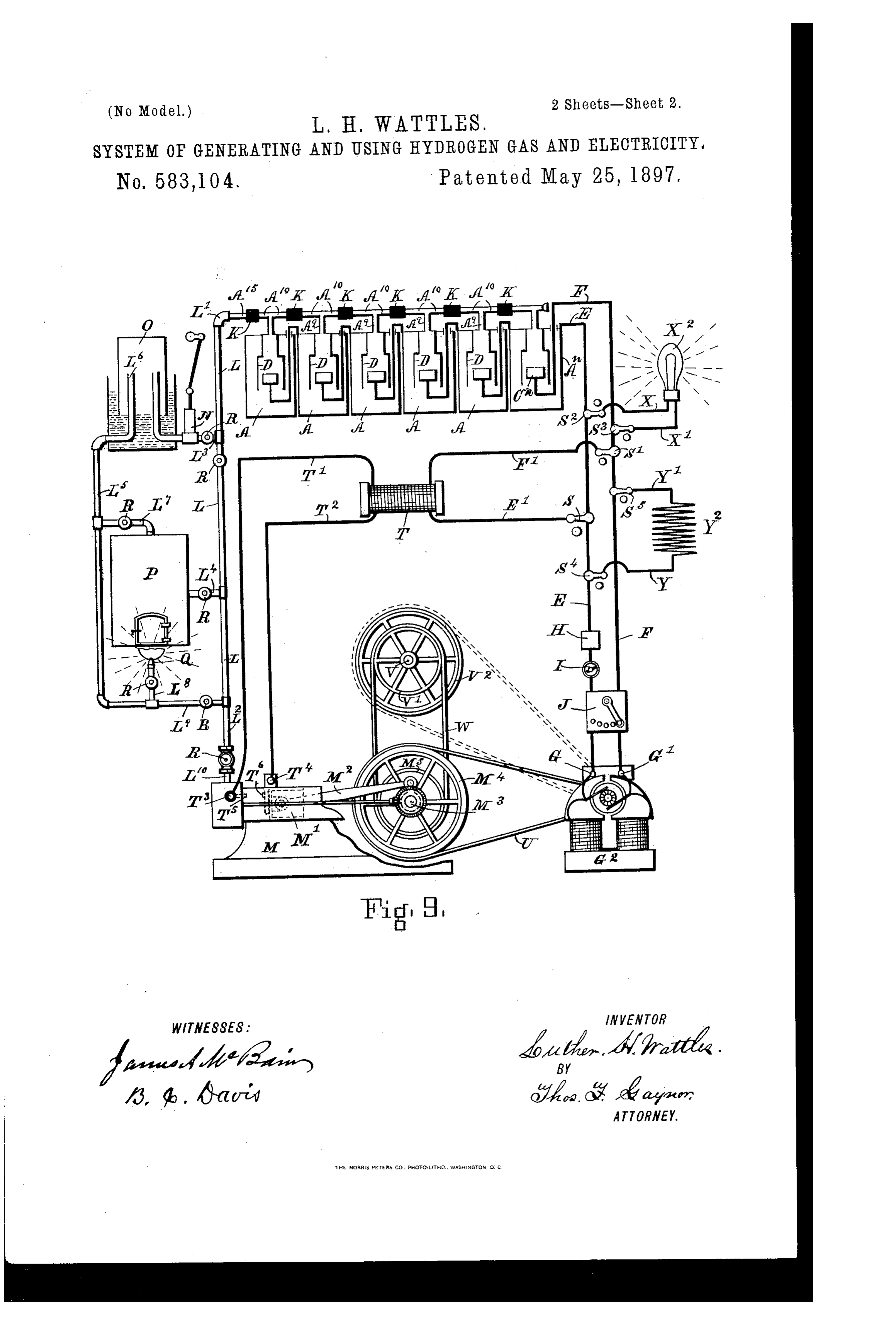
To cle, Luhon, it nually concei'i, 5 is a side elevation of Fig. 4. Fig. G is a SO Be it known that I, LUTHER. H. WATTLES, bottom View of Fig. 4. Fig. 7 is a front cle a citizen of the United States, and a resident vation of the holder and terminal for the of Providence, in the county of Providence Zinc or other electrode. Fig. S is a side ele and State of Rhode Island, have invented cer Vation of Fig. 7. Fig. 9 represents a dia tain new and useful Improvements in Sys gram of a battery of generators having gas tems of Generating and Using Hydrogen Gas and electrical conductors combined there and Electricity, of which the following is a With, a gas-engine connected with the gas specification. conductors, and an electric notor connected O This invention relates to improvements in with the electric conductors and the engine Systems of generating and using hydrogen gas and the motor both applying their power to and electricity; and it consists in providing a the same work-shaft. This figure also shows generator or a number of generators in which how the gas may be conveyed or forced into hydrogen gas and electricity are both gener a suitable holder adapted for its Storage, if ated simultaneously, combining therein gas desired, and it also shows how the gas can be Collecting apparatus having ducts for con Connected with a carburetter if it is desired ducting the gas to the apparatus or mechan to enrich it by the addition there with of car ism intended for its storage or use, with con bon or hydrocarbon gas for illuminating pur ductors for the electricity generated therein poses or in transit to the engine. It also to deliverit to the apparatus intended for its shows how the electric current can be utilized use, and in combining the gas-using appara for electric lighting or heating purposes. The 7 O tus and the electrical apparatus with a com figure further shows how the electric spark mon means of receiving the energy developed which is required for igniting the gas in the by the conversion of the gas and electricity engine is obtained by the induction-coil nec 25 into mechanical power, So that the two forms essary for the purpose and the electrical coln of energy developed in the generator thus be nections of the same with the generator and 75 come collected, converted, and delivered at the engine.
the same time to the same mechanism for its In the drawings, A represents a cup or cell, utilization ol' work. made of copper, to which a cover A' is fitted, The object of my invention is to provide a by means of an internal screw-thread A, to generator of hydrogen gas and electricity and the corresponding external screw-thread. A So to Colnbine With the same such a combination upon the neck A' of the cup A. A packing of apparatus and mechanism capable of con A is fitted around the neck of the cup, so as verting them into the form of useful work as to make a tight joint between the cup and 35 Will Secure by Said means the maximum avail the cover when the latter is Screwed on ill ability and use of the forces developed in the position thereon.
generator. The cover A' has two apertures A' A', The character and purposes of my inven through which the holder B projects and tion will be more fully explained and under upon which the electrode C is mounted when stood by reference to what follows herein in position within the cup A. The electrode and as will be pointed out in the claims, and or zinc C has a central opening C, through 9 O also by reference to the accompanying draw which the threaded extremity B of the holder ings, in Which B passes, and by means of the nut IB° the Figure I represents a front view of the gen Zinc C and the holder B are thereby securely eratOl. Eig. 2 represents a vertical section connected together. The lower portion of of the same. IFig. 3 is a top or plan view of the aperture C is enlarged and Squared, as 95 the generator. IFig. 4 is a top view of the seen at C°, to fit a correspondingly-shaped Zinc or other element employed for the gen portion B of the holder B to prevent the zinc eration of the gas and electric current. Fig. C from turning upon the holder B through
Page 4
accident or otherwise. The cover A' is pro Referring to Fig. 9, AAA represent a se vided with sleeves A' A', having insulation lies or battery of generatol's macle as already bushings AA, by means of which the holder described. The cups and Zincs are connected 7 O B and the cover A may be insulated from alternately in series like any battery of gal each other. Each of the necks 133 of the vanic cells connected up to produce a maxi holder B is provided with a spring retaining mum voltage; but the generator's may be catch B", which is fitted in a groove B" there also connected in multiple arc if quantity in and by means of which the holder will be rather than voltage is required; or modifica 75 held in an elevated position, as indicated by tions of both of these methods of connect O the dotted lines in Fig. 2, by resting upon ing up the poles of a number of cells may be the bushings AAS whenever it is desired to employed, if preferred. The terminal ele lift the zinc out of the solution in the cup ments A C of the battery are connected with and hold it in that position. The sleeves A. the conducting-wires E. F., l'espectively, which A in the cover A retain the holder B with connect in turn with the terminals G. G' of an the Zinc C in a central position in the cup in electric motor G' and to which the current case the latter should be tilted or the like. generated as described is conducted and in The holderl3 is provided with an insulating which it is converted into mechanical power covering B to prevent short-circuiting in the by the motor in the Well-known manner of cup or with it. electric moto's. The circuit-conductors EF, Within the cup A an inverted gas-collec leading to the motor G', have the usual fuse tor D, of copper or other metal, is arranged l, switch I, and resistance-box J, by means and secured to the cover A'. The collector of which the current to the motor can bc con D is of larger dimensions than the zinc C in trolled. Each one of the gas-conductor's A" 9 O that portion of it within which the zinc is A", leading from the gas-collectors DD of the 25 Suspended, so that no contact is made be generator's A A, is connected by means of its tween the two parts of the device, but is nar respective nipples A' A' and couplingSix R, rowed in its dimensions in its upper portion which are made of any suitable insulating ID' and is provided with an aperture D9, which substance not subject to destructive effects 95 also extends through the cover A" and through of the gas, so as to make One continuous coln a gas-conductor A", having nipples A' A'", duit for the gas evolved by the whole series to which conducting tubes or pipes for con of cups that may be in active operation pro veying the gas generated within the collector ducing the gas at the time. The gas is con may be connected. The cover A', which, to ducted by the main duct I, to the gas-engine OO gether with the entire shell of the cup A, MI, one end L' of the duct being connected 35 forms one of the electrodes of the generator with the conductor A at the end of the series or battery, is provided with a binding-post of cells AAA and the other end T. with the A, having a nut A', to which the wire coin gas-engine MI for this purpose. A branch duct ductor for the current generated may be con I leads to a pump N and gas-holder O. An Jo5 nected. The holder B has upon its upper other branch pipe L' leads to a retort or cal extremities a corresponding pair of binding bureter P. The pipe L has a connection L" posts 3' 3" and nuts B B for the other con with the gas-holder O and another, L', with ductor to be connected with. The cover A' the carbureter P, another, LS, with the gas is also provided with an opening A, to which burner Q, and, finally, one, I", which connects IO a stopper A' is fitted for the purpose of fill it again with the main duct L. Valves or 45 ing the cup with the solution required, re cocks R. R. R. are ?itted in the gas-ducts around newing or decanting it, or the like. in the different positions necessary for the The solution required to generate the gas proper control of the flow and manipulation consists of Water and sulfuric acid or any of the gas as required. I 5 other acid that will liberate hydrogen gas and The gas-engine M receives its Supply of gas generate electric cull’rents by its chemical ac through the pipeL", the flow of which is regul tion upon Zinc, iron, or other substance capa lated by the valve R'. Ai" represents a bev ble of such effects. The strength of the so eled gear mechanism which actuates the valve lution is determined by the rapidity with mechanism (not shown) of the engine MI. which the gas and electricity are to be pro The conductors E E are provided with 55 duced and may be Varied from, say, one part, switches S S', having terminal connections (in bulk) to twenty parts of water up to one with the conductors E F", in which the in pal't acid to four parts Water or even stronger duction-coil T is in circuit. The conductor's than this when quick action is necessary. TT have terminals TT at the engine NI The production of hydrogen gas and electric and connections with the coil T, by which a ity by the chemical action of dilute sulfuric circuit between it and the engine MI is estab acid upon Zinc being Well known and under lished whenever the electrodes TT within stood its further description is deemed un the cylinder are in contact. The piston MI", necessary. Niy generator being this de to which the electrode T is attached, carries scribed I will now explain the manner of its the latter away from the electrode T. With use in combination with the other mechanish every out Wald stroke of its operation, there required to carry out the purposes of my in by breaking contact with the electrode Tand vention. producing an electric spark within the gas
Page 5
contained in the cylinder and igniting it at a erated simultaneously with the evolution of right time, so as to cause the proper explosive the gas and the disintegration of the Zinc, is effect necessary in operating gas-engines. converted by the motor into mechanical The power of the engine M is applied, power, which may be applied to the crank through its connecting-rod M, to the crank shaft of the engine or the independent Work shaft M8 in the usual manner. The power of shaft, as already explained. It can thus be the motor G may be applied to the crank-shaft seen that the two forms of energy simulta M8 of the engine M through the belt U and neously generated in the generators are at the 75 wheel M of the engine MI, in which case the same time transmitted to the corresponding O engine crank-shaft becomes the common re mechanisms for converting them into mechan ceiver of power produced by the motor and the ical energy, and in this way the maximum engine. efficiency for useful work is delivered to the A work-shaft V may be provided having a Work-shaft intended for its reception and use. pulley V', over which the belt W runs and is It can also be observed that the electric cur driven by a pulley M on the engine-shaft MI9. rent from the generator also coöperates The shaft V has also a pulley V, to which the through the agency of the induction-coil with belt U from the motor G° may be directly con the gas in igniting the latter in the engine, nected, as shown by the dotted lines, if pre and thus effects the successful operation of ferred. By this arrangement the shaft V be the engine.
comes the receiver of power produced by the The importance of this invention may be engine and the motor and from which it could understood from the fact that for some pur be transmitted otherwise for application or poses primary batteries used for generating U.S. electric currents alone are near the point, as Switches SS in the conductors EF have to economy, of successful competition with 25 terminal connections with the circuit-Wires other methods of generating and using elec XX", in which the electric lamp X* is placed tricity. Now by the additional useful effi and by means of which the electric current ciency obtained by this method of using the from the generators may be caused to pro gas as generated simultaneously and in coln duce light. Switches SS are also placed in junction with the electricity produced it can connection with the conductors E E and hav be seen that it makes it possible for applica ing terminal connections with the loop. YY', tions of this system of producing and using in which the resistance or heating coil Y is power in many ways and under conditions placed in circuit, so that the electric current never successful commercially heretofore. OO may be utilized for heating purposes, if de Its use therefore is in the case of Small units 35 sired. of application peculiarly well adapted as a The operation of my invention will now be means of propulsion for bicycles, tricycles, described: The generators are prepared for motocycles, or horseless vehicles and other use by charging each one of them with a so forms of carriages, cars, and devices for lution of acid of the requisite strength and transportation. Its adaptability for work of filling each one to the level indicated by the this character can be more fully understood dotted line C, b in Fig. 2, in which case all of by reference to another application, dated the Zinc C except its shank or neck becomes December 7, 1895, for Tetters Patent, Serial immersed therein and subject to the dissolv No. 571,338, which I have made and which is O ing and chemical effects of the solution. The now pending before the Office for an improve 45 circuit between the zinc C and the cup A is ment in motocycles. The details of the ap closed, as indicated by the circuit established plication of hydrogen gas in this way to the through the conductors E E and mechanism Operation of gas-engines can also be better connected there with in Fig. 9. The cap or understood by reference to another applica II5 cover A' being adjusted upon the cup and tion for Letters Patent, dated December 7, the stopper A' being in place each generator 1895, which I have also made, Serial No. becomes ready for effective use. 571,337, and which is likewise pending before The gas connections between each of the the Office, for an improvement in gas-engines. generators and the external gas receiving and The invention is likewise applicable to the converting apparatus being in proper connec propulsion of boats, stationary power instal 55 tion and condition, the gas becomes evolved lations, Slmall or large, as may be required. in each generator and passes through the col Large installations of generators for the pro lectors through the ducts and through the duction and use of hydrogen gas and elec engine, where it is used, as produced, in pro tricity can likewise be made and the gas used (lucing mechanical effect, as already de for general lighting and heating purposes as scribed, or it may be delivered into the holder well and Stored in large holders and carbu O and stored there until required for use; reted as commercial illuminating-gas is now or it may be passed through the carbureter treated. The electricity can from the same P and enriched, as already described, by the plant be used for heating, lighting, and power addition of carbon or hydrocarbon gases and purposes, as now done, in addition to or in afterward used in the engine or for illuminat dependent of the combination of the engine ing or other purposes, as desired. and lmotor mechanism herein shown and de The electric current, which becomes gen scribed as in combination.
Page 6
I am aware that it has been proposed to gell IIaving thus described my invention, What erate oxygen and hydrogen gases in a battery I claim, and desire to secure by Letters Pat from the decomposition of water and to use ent, is the electricity generated to also assist in the 1. In combination with a generator, or Se generation of the two gases within the bat lies of generators of hydrogen gas and elec tery in the well-known way of decomposing tricity, the electric conductors connected with water by the electric current and then con the electrodes of the generator or generators, ducting the two gases to separate reservoirs, the electric-dynamo motor mechanislm con where they were to be accumulated and con nected with the electric conductors, a gas-duct 45 IO fined until a pressure of several atmospheres connected with the gas collector or collector's was obtained, and the gases then conducted Of the generator Ol' generators, a gas-engine to separate engines, where they were to be having connection. With the gas - duct and used expansively, like steam or compressed adapted to be operated by the gas from said air, and then to be returned again to the bat generator or generators, and the mechanisms 50 I 5 tery by suitable mechanism devised for the of the engine and motor for the delivery of purpose and then to be used over and over the mechanical power produced by the en again, as before. Now I do not claim. Such a gine and motor, being connected to the same system of gas generation or utilization, and shaft or means of utilization, substantially my system is unlike it, as I conduct the elec as specified.
tricity outside of the generator and utilize it 2. In combination With a generator, or Se 55 directly in running a modern dynamic elec ries of generators of hydrogen gas and elec tric motor if for power purposes or apply it tricity, an electric-dynamo motor mechanism directly to an electric lamp or heater if for connected with the electric generating devices lighting or heating purposes. I use the elec of the generator, a gas-engine mechanism con 25 tricity external to the battery and not within nected with the gas-generating apparatus of it. Then the gas is used explosively in the the generator and the power-delivery mech gas-engine and by its ignition and not merely anisms of the electric motor and the gas-en by its expansion from an artificial compres gine being connected to the same power-re sion, as compressed air is used in an air-en ceiving apparatus, substantially as specified. gine. I also use the gas and electricity in the Signed at Brooklyn, in the county of Kings same engine and cylinder mechanism, and I and State of New York, this 5th day of De collple a modern electric motor and a common cember, A. D. 1895.
gas-engine directly or indirectly to the same ILUTIER II. WATTLES. Work-shaft, and thus generate the two forms Witnesses:
35 of energy in the same generator and utilize G. W. IRWIN, them in the same mechanism for conversion. JAMES A. MICBAIN.
Provenance
- Collection
- Cited prior art
- Original PDF
- patentimages.storage.googleapis.com →
- Pages
- 6
- Method
- pdftotext (the PDF's own text layer) + pdftoppm 300dpi page scans
- Source
- Google Patents bibliographic record
- Granted
- 1897-05-25
- Transcribed from
- patentimages.storage.googleapis.com →