patent · US5687559
Hydrogen-combustion gas turbine plant
18 November 1997
Page 1 — bibliographic record
United States Patent (19) 11 Patent Number: 5,687.559 Sato 45 Date of Patent: Nov. 18, 1997 54 HYDROGEN-COMBUSTION GASTURBINE K. Hiraoka et al., Thermodynamic Performance of an Inter PLANT nal ReheatGas Turbine (IRGT) with Hydrogen Combustion, Report of Ship Research Institute vol. 24, No. 3, (1987), pp.
75 Inventor: Iwataro Sato, Tokyo, Japan 219-238.
73 Assignee: Kabushiki Kaisha Toshiba, Jericha et al., “Towards a Solar-Hydrogen System”, ASME Kanagawa-ken, Japan COGEN-TURBO, IGTI-vol. 6, (1991).
Primary Examiner-Charles G. Freay
Attorney, Agent, or Firm-Finnegan, Henderson, Farabow, 30 Foreign Application Priority Data Garrett & Dunner, L.L.P.
Feb. 20, 1995 JP Japan. .................................... 7-030727 57 ABSTRACT (51] Int. Cl. ................. F02C 6/00; FO2C 1/06 A hydrogen-combustion gas turbine plant includes a first 52 U.S. Cl. ................... 60/39.182; 60/39.17; 60/39.181 System for using inert gas as a Working fluid, and a second 58 Field of Search ............................. 60/39.15, 39.161, system for using steam as a working fluid. The first system
includes a compressor on a turbine shaft, a first heat 56 References Cited exchanger, and a second heat exchanger. The first heat
exchanger heats gas compressed by the compressor and supplies the compressed gas to a high pressure intake of a 2,717,491 9/1955 Barr ..................................... 60/39.182 second turbine. The second heat exchanger cools gas 4,166,362 9/1979 Laurent ... 60/39.18 exhausted from the second turbine and supplies the cooled 5,267.288 11/1993 Frutschi et al... ... 60/39.18 gas to a low pressure intake of the compressor. The second FOREIGN PATENT DOCUMENTS system includes the first heat exchanger and the second heat 6123238 5/1994 Japan .................................. 60/39.465 exchanger. The first heat exchanger uses heat generated by 6-2998.05 10/1994 Japan. combustion of a gas mixture including hydrogen and oxygen to heat the inert gas, and Supplies steam resulting from the
OTHER PUBLICATIONS combustion to a high pressure intake of a first turbine. The W. Peschka, Hydrogen Combustion in Tomorrow's Energy second heat exchanger uses heat from the inert gas of the Technology, Int. J. Hydrogen Energy, vol. 12, No. 7, (1987), first system to heat steam exhausted from a low temperature pp. 1019–1036. outlet of the first turbine, and passes the heated steam to a S. Kan et al., Reheat Gas Turbine with Hydrogen Combus third turbine.
tion Between Blade Rows, 1983 Tokyo International Gas
Turbine Congress, pp. 205-212. 6 Claims, 4 Drawing Sheets
Page 2
Drawing sheet — no readable text.
Page 3
Drawing sheet — no readable text.
Page 4
Drawing sheet — no readable text.

Page 5
Drawing sheet — no readable text.
Page 6
HYDROGEN-COMBUSTION GASTURBINE The plant is generally divided into two parts. PLANT One is a first system, which uses only the steam. The first
BACKGROUND OF THE INVENTION
system has the compressor 1, the combustor 5, and the 2nd turbine 2 thermally functioning in a Brayton cycle, and is a 1. Field of the Invention closed cycle system.
This invention relates generally to a gas turbine plantand, In the system, the steam, compressed by the compressor more particularly, to a gas turbine plant in which its gas 1, is supplied to combustor 5, and heated after burning of a turbine combustor is fed hydrogen as fuel. mixed gas fuel 13 consisting of hydrogen and oxygen. The 2. Description of the Related Art steam, being high-temperature and high-pressure, is Sup Conventionally, a hydrogen-combustion gas turbine plant 10 plied to the 2nd turbine 2 and expands as it drives the shaft 14 to which the compressor 1 and the generator 6 are has a clean energetic source, for non-exhausting carbonic coupled through the turbine shaft 14a and the rotor shaft acid gas (CO2), as distinguished from a plant using fossil 14b, and thus electricity is generated by the generator 6. The fuel which causes green house problems. When hydrogen steam exhausted from the 2nd turbine 2 leads to the com turns into inert steam after burning, the steam or other inert 15 pressor 1 and turns into low-temperature and low-pressure, gas is available as a working fluid for athermal closed cycle after passing through the 1st heat exchanger 7 and the 2nd gas turbine plant without encountering oxidation at high heat exchanger 8.
temperature. In other words, conventional thermal open The other part of the plant is a second system. The second cycle gas turbine plants, feeding fossil fuel for their gas system has the 1st turbine 4, the combustor 5, the 2nd turbines, encounter problems in their parts for use with hot turbine 2, the 1st heat exchanger 7, the 3rd turbine 3, the gas, which parts pass the fluid oxidized in the high tempera condenser 9, the 1st pump 10, and the 2nd pump 11, ture generated during burning of the fuel, or oxygen in the thermally functioning in a Rankine cycle which flows steam fluid. Or Water.
When more parts of the turbine, especially those having Initially, water pressurized by the 2nd pump 11 and then contact with the fluid, become hotter, the likelihood of 25 heated via heat exchange at the 2nd heat exchanger 8 or the oxidation increases. Therefore, these parts must be cooled. 1st heat exchanger 7, turns into high-temperature steam and As is known in the art, when the coolant of the plant is led to the 1st turbine 4 to be used as working fluid for the increases, the thermal efficiency of the plant decreases. In plant. In other words, the water is led to these heat exchang addition, cooling these parts with coolant in the plant has ers and is heated by heat exchange with hot gas exhausted been studied, as the temperature of fluid gets higher. 30 from the 2nd turbine 2, and turns into high-pressure, high Rising the maximum temperature of the turbine to temperature steam. Then the steam is supplied to the 2nd increase the thermal efficiency of the planthas been noticed, turbine 2 through the combustor 5. The steam expands as it and with this technical development, maximum temperature drives the turbine shaft 14a, and is led to the 1st heat of the planthas recently ascended rapidly. But nowadays, the exchanger 7. At the 1stheat exchanger 7, the steam is cooled maximum temperature has been growing to a peak while 35 by heat exchange with the water exhausted from the 2nd increase of the efficiency caused by rising of the temperature pump 11 through the 2nd heat exchanger 8, and then is led has been inferior to that of decrease caused by expanding of to the 3rd turbine 3. The steam expands as it drives the the fluid for cooling the plant. turbine shaft 14a, and is supplied to the condenser 9 where A plant having a gas turbine combustor fed hydrogen is the steam is cooled, and turns into water. Some of the water interesting for other reasons. To wit, hydrogen, unlike fossil condensed at the condenser 9 is pumped by the 1st pump 1D fuel, may be generated everywhere if there is electric power. or the 2nd pump 11, and supplied to the 2nd heat exchanger That is to say, some countries, having enormous potential 8 for recycling. The remainder is pumped by the 1st pump resources like water withoutindustrial or consumer demand, 10 and exhausted out of the second system through drain 12. are capable of generating the hydrogen as an energy source A quantity of water exhausted through the drain 12 is and exporting the hydrogen. 45 equal to that resulting from the combustion of the hydrogen As described above, the plant fed hydrogen is interesting and oxygen fuel 13 at the combustor 5. and research for generation, transportation, and storage of While generating hydrogen is more expensive than refin hydrogen has been executed. ing crude petroleum, the maximum temperature of a plant One of these types of remarkable gas turbine plants, fed having gas turbines fed hydrogen fuel must be higher than hydrogen as fuel for its gasturbines, is shown in FIG. 6. FIG. 50 that of a planthaving gasturbines fedfossil fuel. So a radical 6 shows a systematic diagram of the conventional gas countermeasure for oxidization in hot temperature at these turbine plant fed hydrogen as fuel. turbines is needed, and what can be seen in FIG. 6 is a The plant has a generator 6 which is connectable electri conventional solution to the problem by using the steam, cally to a power system through its output lines and driven being inert gas, for working fluid in the plant. by following turbines. A 1st turbine 4 is mechanically 55 The steam running through passages in the plant has a coupled to a turbine shaft 14a that is connectable to a rotor significantly higher specific heat than burnt gas generated in shaft 14b. A compressor 1 is mechanically coupled to the conventional gas turbine plants in which gas turbines are fed turbine shaft 14a. A 2nd turbine 2 is mechanically coupled fossil fuel. Therefore, a number of stages in these turbines to the turbine shaft 14a, and a 3rd turbine 3 is also coupled driven by the steam are needed especially for cooling. to the turbine shaft 14a. The plant has a combustor 5, a Increasing the number of stages causes a decrease of condenser 9, a 1stheat exchanger 7, a 2nd heat exchanger 8, efficiency of the plant as is known in the art, and after a 1st pump 10, and a 2nd pump 11, and all these mechanic adopting stages fewer stages have been used in the gas elements are mechanically coupled to the turbine shaft 14a turbine. Cooling steps of steam-driven gas turbine plants or thermally connected through plural passages which flow require twice as many stages as that of the conventional only steam or water as working fluid, as shown in FIG. 6. In 65 ones, and that causes loss of thermal efficiency. So an addition, the turbine shaft 14a is mechanically connectable improvement of thermal efficiency at high-temperature with the rotor shaft 14b as a coupled shaft 14. comes offset with the loss.
Page 7
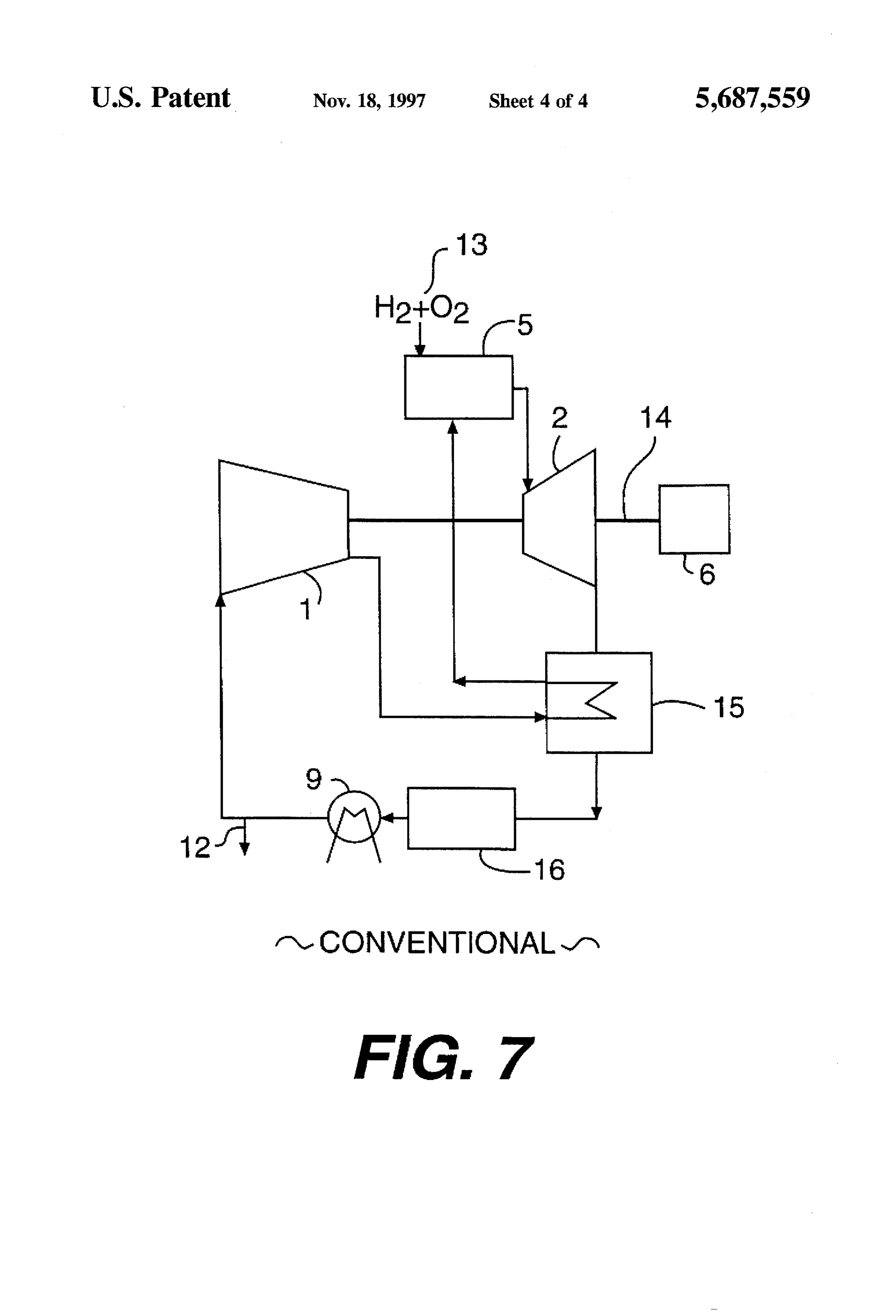
The steam, flowing in a cycle of the plant at high When using the inert gas for working fluid, all the fluid temperature, sometime causes corrosion in passages of the ought to be conducted to condenser 9, and the quantity of plant, and makes the passages fatigue. Therefore, the con heat of the plant decreases by increasing exhaustion of ventional plant is unreliable after long time use, and these thermal capacity from the thermal system. problems have not been solved. Accordingly, a primary object of this invention is to A conventional approach to the problem is shown in FIG. provide a hydrogen-combustion gas turbine plant for solving 7. the problem of steam corrosion without increasing the Working fluid, running through passages shown in a plant number of cooling stages. Yet another object is to increase system of FIG. 7, is substantially inert gas. In the inert gas, the quantity of heat of the plant by supplying a portion of the there may be steam or water, fed oxygen and hydrogen as O working fluid to a condenser.
fuel after burning. SUMMARY OF THE INVENTION First, the inert gas is compressed by a compressor 1, While the invention is particularly shown and described supplied to a regenerative heat exchanger 15 where it is with reference heated, and supplied to a combustor 5. Then the gas becomes understood by those to preferred embodiments thereof, it will be a mixed gas after it is fed with hydrogen and oxygen as fuel 15 and details can be made skilled in the art that changes in form 13, being extremely high-pressure and high-temperature. without departing from the spirit This mixed gas is led to a 2nd turbine 2, where the mixed gas and scope of the invention. expands and becomes low-pressure, high-temperature, Many other features, advantages and additional objects of mixed gas while driving the compressor 1 through a shaft 14 the present invention will become manifest to those versed coupled to the 2nd turbine 2, and generating electricity at a whichin the art upon making reference to the detailed description generator 6 also coupled to the shaft 14. follows and the accompanying sheets of drawings. In accordance
The gas exhausted from the 2nd turbine 2 is led to the hydrogen-combustion with one aspect of the invention, a regenerative heat exchanger 15 and cooled by heat exchange tem gas turbine plant includes a first sys with gas supplied to the combustor 5. The gas is cooled at including a compressorasona working for using inert gas the fluid, the first system turbine shaft, a 1st heat a heat recovery steam generator (HRSG) 16 by heat 25 exchanger, and a 2nd heat exchanger, the 1st exchange and, becomes cooled, low-pressure-mixed gas. heating gas compressed by the compressor heat exchanger and supplying
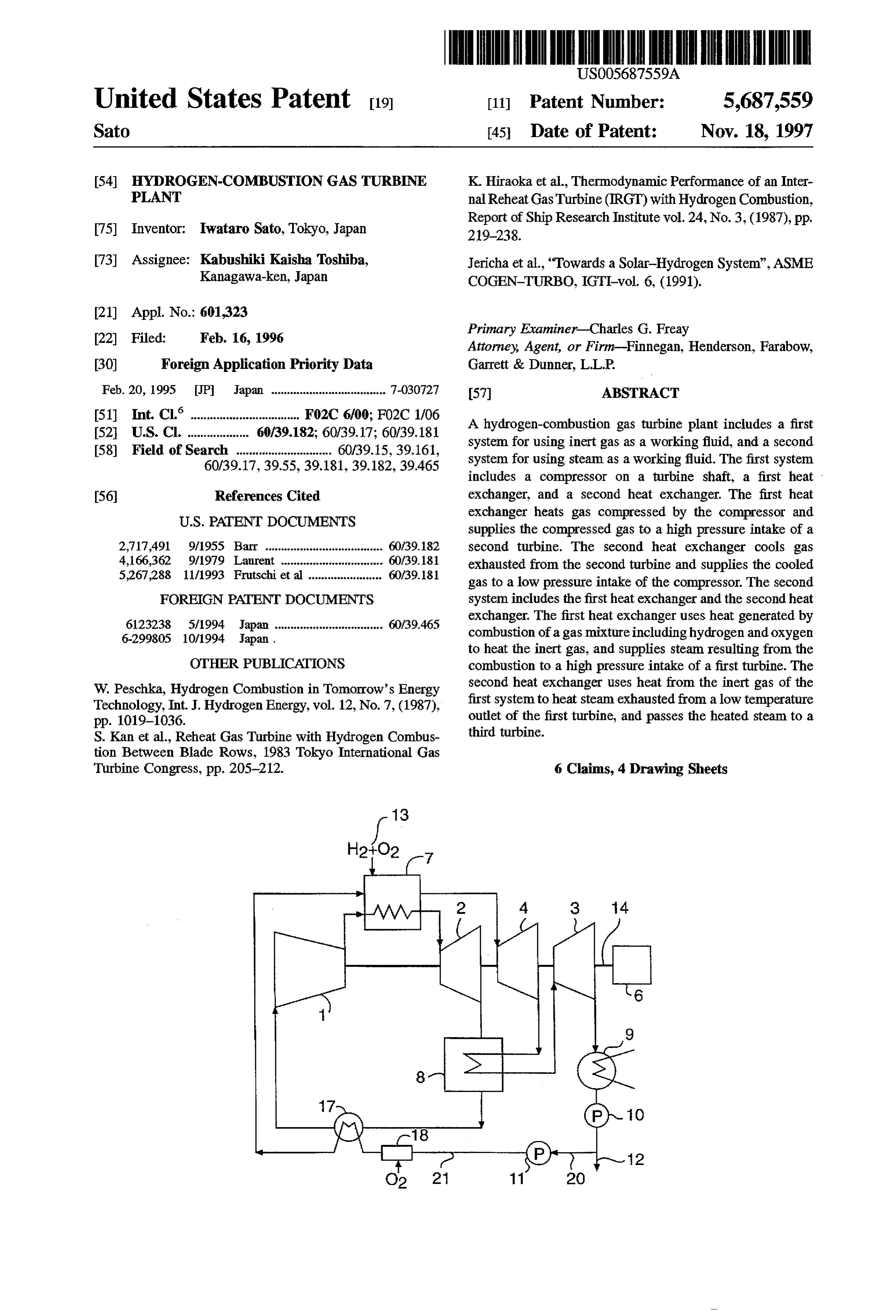
This cooled low-pressure mixed gas including steam is led the compressed gas to the high pressure intake of the 2nd to condenser 9 for condensing and cooling below dew point turbine, the 2nd heat exchanger cooling gas exhausted from of the steam. Then all the steam in the inert gas turns into the 2rd turbine and supplying the cooled gas to a low water and is exhausted from the thermal system through 30 pressure intake of the compressor; and a second system for drain 12. The inert gas is then supplied to the compressor 1 using steam as a working fluid, the second system including again. the 1st heat exchanger and the 2nd heat exchanger, the 1st At the HRSG 16, steam produced from thermal increase heat exchanger using heat generated by combustion of a gas of the mixed gas, generates electrical power by driving a mixture including hydrogen and oxygen to heat the inert gas, steam turbine (not shown) connected to the generator 6 or 35 the 1st heat exchanger supplying steam resulting from the another means. combustion to a high pressure intake of the 1st turbine, the In this plant, the inert gas used as working fluid has a 2nd heat exchanger using heat from said inert gas of said specific heat nearly equal to conventional burnt gas. Yet outletsystem first to heat steam exhausted from a low temperature of the 1st turbine, the 2nd heat exchanger passing the using the inert gas like argon or nitrogen requires a nearly heated steam to the 3rd turbine. equal number of stages for cooling in a gas turbine, Such as 2nd turbine 2, so it does not have the problems associated BRIEF DESCRIPTION OF THE DRAWINGS with increasing the number of stages for the system shown FIG. 1 is a systematic diagram showing a hydrogen in FIG. 6. The inert gas includes less steam than that of the combustion gas turbine plant according to a first embodi thermal cycle described in connection with FIG. 6, so the ment of the present invention;
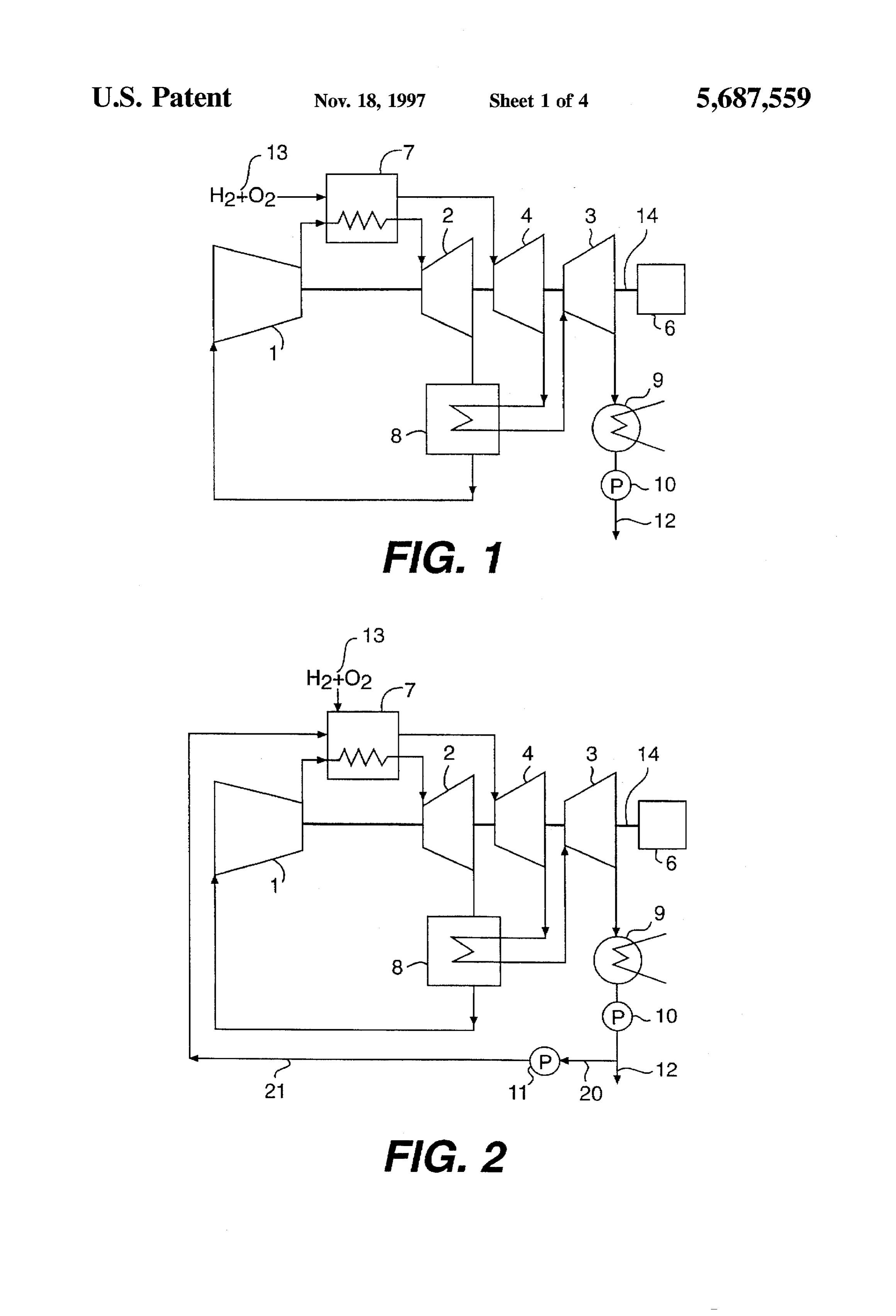
problem of corrosion of steam is solved somewhat. 45 FIG. 2 is a systematic diagram showing a hydrogen Only some of the working fluid circulating through the combustion gas turbine plant according to a second embodi thermal system described in FIG. 6 exchanges its heat at the ment of the present invention;
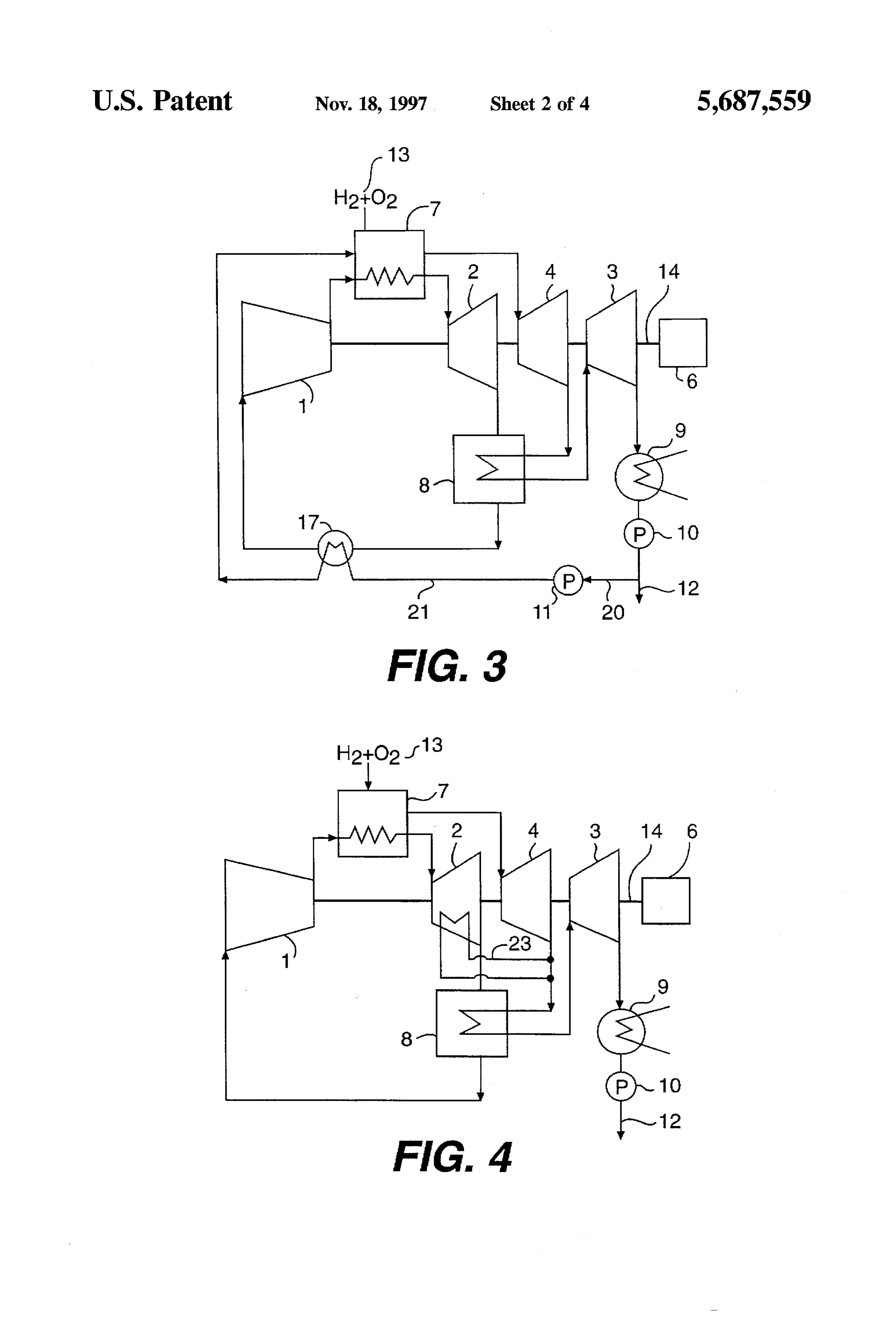
condenser 9, but all the working fluid circulating through the FIG. 3 is a systematic diagram showing a hydrogen thermal system described in FIG.7 exchanges its heat at the combustion gas turbine plant according to a third embodi condenser 9, and all the steam generated at the HRSG16 is 50 ment of the present invention;
terminally supplied to a condenser (not shown) and heat FIG. 4 is a systematic diagram showing a hydrogen exchanges with outside refrigerant. combustion gas turbine plant according to a fourth embodi Since the thermal system described in FIGS. 6 or 7 is ment of the present invention;
F.G. 5 is a systematic diagram showing a hydrogen fundamentally a closed cycle, thermal capacity exhausted from these systems is only from the condenser 9. The less 55 ment combustion gas turbine plant according to a fifth embodi the thermal capacity exhausted from the condenser 9, the of the present invention; more the quantity of heat increases. Consequently, the FIG. 6 is a systematic diagram showing a hydrogen quantity of heat of the system described in FIG. 7 is offset combustion approach;
gas turbine plant according to a conventional and by increasing of the number of stages for cooling. FIG. 7 is a systematic diagram showing a hydrogen As described above, running steam or water for the combustion gas turbine plant according to another conven working fluid through mechanical elements in a conven tional approach.
tional hydrogen-combustion gas turbine plant which includes a combustor fed hydrogen as fuel has problems. As DESCRIPTION OF THE PREFERRED the number of cooling stages increases, the quantity of heat EMBODIMENT decreases. And as the stages increase, the plant is less likely 65 Preferred embodiments of the present invention will be to operate safely over a long time because of corrosion described below with reference to the accompanying draw caused by steam. ings.
Page 8
Referring now to the drawings and particularly to FIG. 1, Aratio of the working fluid led to the condenser 9 to a sum which is a systematic diagram showing a hydrogen of running working fluid is small, and the thermal efficiency combustion gas turbine plant according to a first embodi of the plant remains because heat of working fluid is not ment of the present invention, the invention is shown exhausted out of the system through the condenser 9. generally in this figure, however, this invention is not limited 5 Therefore, the plant of present invention can increase the to such an annular configuration and may be employed with thermal efficiency of the plant more than conventional plants equal effectiveness in hydrogen-combustion gas turbine shown in FIGS. 6 or 7.
plants of the well-known inert gas running system type.
The hydrogen-combustion gas turbine plant shown in sionIn after addition, decreasing reliability caused by steam corro long time use of the plant is effectively avoided
FIG. 1 consists of two of parts. because the maximum temperature point of the plantis in the One partis a first system thermally behaving in a Brayton first system running the inert gas. cycle and comprises a compressor 1, a 1stheat exchanger 7, A hydrogen-combustion gas turbine plant according to a a 2nd turbine 2, a 2nd heat exchanger 8, and a passage connecting these components, as shown in FIG. I. The first second embodiment of the present invention will now be System runs working fluid of inert gas, for instance argon or 15 described with reference to FIG. 2. The same reference nitrogen. numerals as used in FIG. 1 are also used in FIG. 2 for The other part of the plant is a second system which corresponding or identical elements to avoid repeating their thermally behaves in a Rankine cycle and comprises the 1st descriptions, and only the difference between the first and heat exchanger 7, a 1st turbine 4, the 2nd heat exchanger 8, second embodiments will be discussed below. a 3rd turbine 3, a condenser 9, a 1st pump 10, and a passage 20 According to the second embodiment, the hydrogen connecting these components, as shown in FIG. i. The combustion gas turbine plant has a branch passage 20 from second system runs steam or water as a working fluid. an outlet of the 1st pump 10 to drain 12 in the second system In other words, the working fluid of this invention com of the above mentioned first embodiment.
prises only the inert gas fluid in the first system and only the The second embodiment of the hydrogen-combustion gas steam in the second system. During heat exchange at the 1st 25 turbine plant can make the water as the working fluid of the heat exchanger 7 or the 2nd heat exchanger 8, they are never plant branch off through the branch passage 20 and lead to mixed with each other. a low temperature side of the 1stheat exchanger 7 after it is A high-temperature heat source for the first system is pressurized by a 2nd pump 11.
caused by burning of hydrogen and oxygen at the 1st heat The water led to the 1st heat exchanger 7 is heated by exchanger 7, and a low-temperature heat source of the 30 combustion of hydrogen and the oxygen supplied to the 1st system is caused by exhausting heat of the second system by heat exchanger 7 as fuel 13. Then the water becomes heat exchange at the 2nd heat exchanger 8. high-pressure, high-temperature steam and supplies heat to In the first system, the inert gas compressed by compres the first system that thermally behaves in a Brayton cycle at sor 1 is led to the 1stheat exchanger 7, heated, and becomes the 2nd heat exchanger 8.
high-pressure, extremely high-temperature, inert gas. This 35 A thermal efficiency of the hydrogen-combustion gas high-pressure, extremely high-temperature, inert gas is led turbine plant is only governed by pressure or temperature, to the 2nd turbine 2 and becomes low-pressure, high especially a quantity of heat caused by heat exchange temperature, inert gas by expansion, and also generates between the first system and the second system at the 1st electric power by driving the compressor 1 coupled to a heat exchanger 7 or the 2nd heat exchanger 8 for each turbine shaft 14a and a generator 6 coupled to a rotor shaft machine of the plant. Therefore, the best mode for operating 14b through a shaft 14. The low-pressure, high-temperature, of the plant might not be achieved by selecting the first inert gas exhausted from the 2nd turbine 2 is led to the 2nd embodiment. The second embodiment of the plant has the heat exchanger 8, becomes low-pressure, low-temperature, branch passage 20 branching off from the 1st pump 10 and inert gas by cooling, and is then led to the compressor 1 coupling to a lower pressure intake of the 2nd pump 11 and again. 45 a channel 21 between the 2nd pump 11 and the 1st heat In the second system, fuel 13, such as hydrogen and exchanger 7. The plant of second embodiment can govern a oxygen at a high pressure, burns in the 1st heat exchanger 7 ratio of quantity of heat between the first system and the and becomes high-pressure, high temperature steam supply second system by controlling the running fluid in the branch ing heat to the first system. This high-pressure, high passage 20 and the channel 21. Therefore, the plant can be temperature steam expands at the 1st turbine 4 and becomes 50 appropriately operated at the best mode, which is the maxi low-pressure, low-temperature steam while driving the shaft mum point of the thermal efficiency of the plant. 14. This low-pressure, low-temperature steam is led to the A hydrogen-combustion gas turbine plant according to a 2nd heat exchanger 8 and becomes low-pressure, high third embodiment of the present invention will now be temperature steam from heat supplied by the first system. described with reference to FIG. 3. FIG. 3 shows the third This low-pressure, high-temperature steam is led to the 3rd 55 embodiment of the present invention for the hydrogen turbine 3, expands, and becomes extremely low-pressure, combustion gas turbine plant.
low-temperature steam while driving the shaft 14. This The plant of this embodiment has a cooler 17 in the first extremely low-pressure, low-temperature steam is led to the system between a low temperature side of the 2nd heat condenser 9 and becomes hot water by cooling. Then the exchanger 8 and a low pressure side of the compressor 1. In water is exhausted out of the plant from drain 12 by a 1st the second system, the plant has the cooler 17 between a pump 10. high-pressure side of the 2nd pump 11 and allow temperature In the manner as stated above, the thermal maximum side of the 1st heat exchanger 7 added to the plant of the point is at an intake of the 2nd turbine 2, except in the 1st second embodiment. The water running through the channel heat exchanger 7 where burning of the mixed gas takes 21 is pumped by the 2nd pump 11 and used for coolant in the place. Decreasing thermal efficiency of the plant is pre 65 cooler 17 of the first system.
vented because the number of cooling stages for running the Since the plant of this embodiment has the cooler 17 in the inert gas as working fluid in the system is not increased. first system, the working fluid, inert gas exhausted from the
Page 9
2nd heat exchanger 8, is cooled by heat exchange with the is fed to the 1st heat exchanger 7 as fuel, may be used for coolant. Then the gas cooled at the cooler 17 becomes the heat source for cooling of coolant in the cooler 17. low-temperature, low-pressure inert gas, and is led to a low In addition, when using the evaporation heat for heat pressure side of the compressor 1. source for cooling in the condenser 9, the plant loses no On the other hand, in the second system, the water quantity of heat out of the plant, and the heat efficiency of pressured by the 2nd pump 11 is heated at the cooler 17 by the plant may increase substantially.
heat exchange with the gas exhausted from the 2nd heat A hydrogen-combustion gas turbine plant according to a exchanger 8, turns into hot water, and is led to the 1st heat fourth embodiment of the present invention will now be exchanger 7. described with reference to FIG. 4. FIG. 4 shows the fourth The temperature at an intake of the compressor 1 is nearly 10 embodiment of the present invention for the hydrogen the temperature at an outlet of the 1st turbine 4 in the second combustion gas turbine plant.
embodiment. In the first system, the gas exhausted from the This embodiment of the plant has a means for branching 2nd turbine 2 is led to the low pressure side of the com 23 added to the plant of the first embodiment. The means for pressor 1 after running through the 2nd heat exchanger 8. branching 23 is branched off from an outlet of the 1st turbine When the gas exhausted from the 2nd turbine 2 flows 15 4 and leads partial steam exhausted from the turbine to hot through the 2nd heat exchanger 8, the gas exchanges heat parts (ex. fixed blades) mounted in the 2nd turbine 2 without with steam which is exhausted from the 1st turbine 4, and is mixing with the inert gas as working fluid of the 2nd turbine not hotter than the gas. This is because the temperature at the 2. The means for branching 23 also leads the steam to the intake of the compressor 1 is nearly the temperature at the 2nd heat exchanger 8 where it flows together with steam not outlet of the 1st turbine 4 in the second embodiment. So, the supplied to the 2nd turbine 2.
plant described in the second embodiment has the problem In other words, part of the steam exhausted from the 1st of preventing increases of total power of the plant, which is turbine 4 is branched off to the means for branching 23, is caused by not gaining heat drop of 1st turbine 4 in the first led to the fixed blades mounted in the 2nd turbine 2 without System. mixing with the inert gas, is supplied with heat from the inert When solving the problem by increasing the heat drop of 25 gas from heat exchange with the inert gas, is flowed together the first system, another problem occurs. To wit, increasing non-supplied steam to the 2nd turbine 2, and is led to the 2nd the heat drop of the first system is especially necessary to heat exchanger 8 through the means for branching 23. decrease temperature of the steam exhausted from the 1st In addition, the mixing of the steam as coolant with the turbine 4 by means of increasing heat consumption at the 30 inert gas in the 2nd turbine 2 at the fixed blades causes turbine in the second system. pressure loss for the inert gas in the first system, which may But using the means for solving the problem, the steam decrease adiabatic efficiency of the 2nd turbine 2, and which led to the 1st turbine 4 would include water caused by may also cause decreasing thermal efficiency of the plant. condensation. Consequently, mixed fluid including the Having the means for branching 23 in the plant according steam and the water is supplied to moving blades of the 1st 35 to the fourth embodiment, causes no decreasing of pressure turbine 4, which is turning at high speed around the shaft 14. loss for the inert gas in the first system, and may increase the If the mixed fluid includes the Water, the Water is also led to thermal efficiency of the plant to a level greater than that of the blades of the turbine, and the blades can be damaged by conventional plants.
the water. A hydrogen-combustion gas turbine plant according to a That is why decreasing temperature of the steam fifth embodiment of the present invention will now be exhausted from the 1st turbine 4 is so difficult to increase the described with reference to FIG. 5. FIG. S shows the fifth heat drop of the first system. embodiment of the present invention for the hydrogen By the way, since decreasing the temperature at the intake combustion gas turbine plant.
of the compressor 1 is almost impossible, the temperature is This embodiment of the plant has an oxygen dissolver 18, higher than that of a conventional plantfed fossil fuel for its 45 which dissolves or atomizes oxygen in the water pumped by gas turbine. the 2nd pump 11 in the second system, and which is added Generally speaking, the more the temperature of working to the plant of the third embodiment. The oxygen dissolver fluid at an intake point for a gas turbine rises, the more 18 is positioned between a high pressure side of the 2nd power of the gas turbine decreases. So the power of the gas pump 11 and a low temperature side of the cooler 17. The turbine used for the plant of second embodiment is inferior 50 oxygen dissolved by the oxygen dissolver 18 is enclosed by to that of the gas turbine used for the conventional one fed the water pumped by the 2nd pump 11 through the channel fossil fuel. 21. The oxygen enclosed in the water chemically combines Using the plant of the third embodiment, where the cooler with impurities, which are present in the water. Because the 17 decreases temperature of a low pressure side of the impurities are chemically combined with the oxygen, they compressor 1, the power of the plant rises as high as 55 may not stick and form scale. The oxygen chemically conventional ones. In addition, the moving blades may not combined with the impurities is led to the 1stheat exchanger be destroyed. 7 and is burnt with hydrogen fed as fuel, so that it turns into Since the heat source for cooling of the cooler 17 is the steam as working fluid of the second system. water, and since partial drain 12 branched off from the As described above, the plant of fifth embodiment shall branch passage 20 at a high pressure side of the 1st pump 10, prevent increase of pressure loss in the plant by preventing or the heat source for heating of the cooler 17 is thoroughly sticking of the scale inside the channel 21. In addition, the used among the machines of the plant, the plant never loses plant may prevent oxidation at high temperature among quantity of heat from the plant. Therefore, heat efficiency of machines of the plant.
the plant should recover or increase rather than decreasing What is claimed is:
during generation of the power by the plant. 65 1. A hydrogen-combustion gas turbine plant including an In another variation of this embodiment, evaporation heat electrical power generator having a rotor shaft, a first turbine from the mixed gas, such as hydrogen or the oxygen which on a turbine shaft coupled to the rotor shaft, a second turbine
Page 10
on said turbine shaft, a third turbine on said turbine shaft, 2. A hydrogen-combustion gas turbine plant, as set forth and a condenser connected to an outlet of said third turbine, in claim 1, further comprising said third turbine outputting steam and said condenser a branch passage for receiving water exhausted from said condensing the steam output from said third turbine, said condenser and plant comprising: a pump for pumping at least a portion of the water (a) a first system for using inert gas as a working fluid, the exhausted from said condenser to a low temperature first system including a compressor on said turbine side of said first heat exchanger. shaft, a first heat exchanger, and a second heat 3. A hydrogen-combustion gas turbine plant as set forth in exchanger, the first heat exchanger heating gas com claim 2, further comprising a cooler for cooling said inert pressed by said compressor and supplying said com O gas of said first system, said cooler transferring heat from pressed gas to a high pressure intake of said second inert gas between said second heat exchanger and said turbine, the second heat exchanger cooling gas compressor to water between said pump and said first heat exhausted from said second turbine and supplying the exchanger.
cooled gas to a low pressure intake of said compressor; 4. A hydrogen-combustion gasturbine plantas set forthin and 15 claim 1, 2 or 3, further comprising a channel for directing at (b) a second system for using steam as a working fluid, the least a portion of steam exhausted from said first turbine to second system including said first heat exchanger and said second turbine to cool a portion of the second turbine, said second heat exchanger, said first heat exchanger said channel returning the directed steam to an intake of said using heat generated by combustion of a gas mixture 20 second heat exchanger.
including hydrogen and oxygen to heat said inert gas, 5. A hydrogen-combustion gas turbine plant as set forth in said first heat exchanger supplying steam resulting claim 3, further comprising an oxygen dissolver between from the combustion to a high pressure intake of said said pump and said cooler.
first turbine, said second heat exchanger using heat 6. A hydrogen-combustion gas turbine plant as set forthin from said inert gas of said first system to heat steam 25 claim 2, further comprising an oxygen dissolver between exhausted from a low temperature outlet of said first said pump and said first heat eXchanger.
turbine, said second heat exchanger passing the heated steam to said third turbine. * : * : :
Provenance
- Collection
- Cited prior art
- Original PDF
- patentimages.storage.googleapis.com →
- Filed
- 1996-02-16
- Pages
- 10
- Method
- pdftotext (the PDF's own text layer) + pdftoppm 300dpi page scans
- Source
- Google Patents bibliographic record
- Granted
- 1997-11-18
- Inventors
- Iwataro Sato; Toshiba Corp
- Transcribed from
- patentimages.storage.googleapis.com →