patent · US1876879
Charge-forming apparatus for internal combustion engines
13 September 1932
Page 1
Drawing sheet — no readable text.
Page 2
Patented Sept. 13, 1932 1876,879
UNITEDwALTER,STATES PATENT OFFICE
DBABOLD, OF DETROIT, MICHIGAN
CELARGE-FORMING APPARATUS FOR INTERNAL COMBUSTION ENGINES
Application filed August 7, 1929. serial No. 384,200.
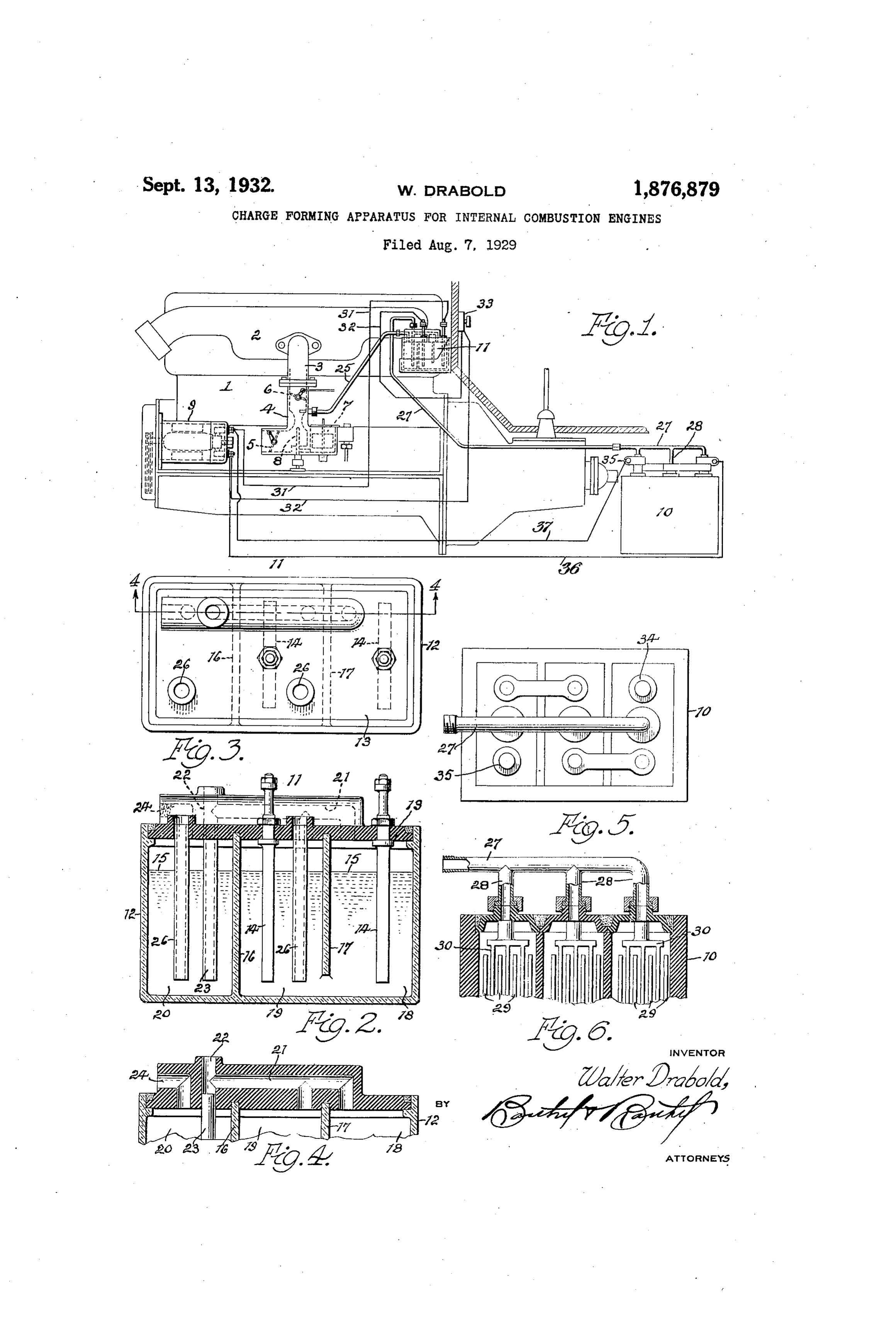
This invention relatesto the method of pro age battery ducing and supplying gaseous charges to in thereto and showing a conduit connection for drawing of the fumes or gases ternal combustion-engines, and its object is to generated therein; and - Fig. 6 is a longitudinal section through Fig.
provide a charge the constituents of which 5 and are so derived as to provide a different pro For conduit the connection to the battery.
purpose of illustrating suitable
portioning of these constituents than has means for carrying into practice the present heretofore been done, to the end that an in process of forming combustible charges and crease in power and efficiency of the engine is supplying the same to an internal combustion secured. A further object isto employ means engine, a particular arrangement and combi 60 0 commonly used for other purposes in engine operation, for producing a gas for combina ing nation of devices is shown in the accompany drawing, but it will be understood that tion with the usual charges comprising hy this apparatus drocarbon vapor and air, and to provide of the appended may be varied within the scope additional gases otherwise derived, for in claims without departing 65 15 troduction into the carburetted air stream for from the spirit of the invention. . further varying the character of the com orIn the drawing 1 indicates as a whole, a gas bustible gases introduced into the engine cyl wellinternal combustion engine of an old and known type and construction wherein
With the above and other ends in view, the the combustible fluid is conducted to the sev 0. 20 invention consists in forming a carbonated eral cylinders (not shown) of the engine, vapor stream, employing this flow as a carrier through a combined intake and exhaust mani for gases otherwise derived, and introduced fold 2 of any suitable form. These gases are drawn into the manifold through a pipe con therein after the formation of such vapor and nection 3 to the lower end of which pipe the prior to the entrance of the flow into the en usual carbureter 4 is connected in the usual 75 25 gine cylinder, the invention further consist ing in utilizing the usual storage battery as manner to supply.charges of vaporized hy a source of gas supply, and providing a gen drocarbon (such as gasoline or other hydro erator arranged to serve as a purifier for the carbon oils) and atmospheric air. This carbureter embodies the usual air or gases supplied by the battery, the gases from choke valve 5 and throttle valve 6 together 80 30 both battery and generator, being combined with the usual fuel supply chamber 7 and with the main gas flow of carburetted air, to spray produce engine charges varying in constituen spray nozzle 8 whereby a finely divided fuel is introduced into the ingoing air cies according to engine operation.
. The invention further consists in the mat stream to form the proper gaseous mixture. 35 ters hereinafter pointed out and more partic The mixture thus formed provides in the ularly set forth in the appended claims, ref usual pactice, the sole charge content for the erence being had to the accompanying draw engine and is drawn into the engine cylinders. by engine inspiration where it is compressed ing in which
Fig. 1 is a view showing the usual internal and ignited, whereupon certain chemical re actions and changes take place, the carbon 90 40 combustion engine in side elevation and illus trating an application thereto of a charge the oxygenthe content of hydrocarbon and a portion of forming system embodying the present in carbon-dioxid, while ofcontent the the air reacting into hydrogen content of vention;
Fig. 2 is a detail view of a water-gas gen the hydro-carbon reacts with the oxygen con 45 erator showing the same in vertical longitu tent of the air, the nitrogen content of the
dinal section; air being practically inactive. Fig. 3 is a plan view of Fig. 2; The present invention relates to the pro Fig. 4 is a sectional detail substantially will giveofincreased duction a combustible gaseous fuel which efficiency and power in 0.
upon the line 4-4 of Fig. 3; the operation of the engine, this resuit being 50 Fig. 5 is a plan view of an ordinary stor
Page 3
secured through varying the character of the vided, one end of which opens into the top charge by decreasing the percentage of inac the chamber 20, and into the opposite end tive nitrogen content and increasing the oxy of gen content, while retaining the use of at of which is secured a pipe or tube 25 (see Fig. 1) leading to the up-take pipe of the car mospheric air as part of and a carrier for the bureter 4 and tapped into said pipe between charge. This variation in the charge is the nozzle 8 and throttle valve 6 thereof. brought about by producing, by engine op Air inlet tubes eration, gases derived from other sources within openings26in (see the
Fig. 2) are secured cover 13 of this gas
O than through the carbureter, and introducing generator and extend downwardly in the into the carburetted air flow these gases water in the chambers 19 and 20 thereof to 75 which contain a high percentage of oxygen admit content in a form to readily unite with the neath atmospheric air to these chambers be the water therein.
hydrocarbon vapor without dilution of the Connected into the upper end of the bore ultimate charge entering the engine cylinder, is a tube 27 and at its opposite end this
this supplemental or enriching flow being in 22 tube is formed with branches 28 each in open 80 a complete gaseous form before its introduc communication with a separate chamber of tion into the main flow and its content in the storage battery 10, the interior of the cluding a high percentage of active and a low battery box being divided, in the usual man percentage of inactive constituents in pro 20 ducing engine power, and effective in coun ner into separate chambers within which are teracting the formation of carbon in the en located the several grids 29 and plates 30, all 85 glne. arranged in the usual manner with the grids These additional charge forming gases are shown)and plates immersed in electrolyte fluid (not 25 derived by means controlled by engine op Wirescontained in each chamber. or electrical conduits 31 and 32 lead eration and the production of this gas is therefore controlled according to engine from the terminals of the generator 9 to the 90 terminals of the plates 14 in the chamber 18 needs, and further, two sources of supply for and 19 of the gas generator 11 and within this such gas is provided, one co-operating with circuit is connected a switch 33, preferably
the other to purify the gas produced by said located upon the dash or other convenient other, which other is a device necessary in part of the motor vehicle, the operation of modern gas engines, the 34 and 35 of the battery 10andaretheelectrically terminals 95 gas produced in its operation, not being or connected, by wires 36 and 37, in any suitable dinarily utilized for any useful purpose. manner to the generator 9 for supplying cur
As shown in the drawing 9 indicates the rent to said battery and keeping the same usual electric generator which is connected charged. 00 in the usual manner to the crank shaft or In the operation of the above described sys other moving part of the engine for gener tem, at low engine speeds, when the genera ating current to be supplied to the usual stor tor age battery 10 and for other purposes. In the 9 is producing but little current, the effect 40 present arrangement, current produced by of such current in decomposing the water the generator 9 is passed through a gas pro slight and liberating its constituent gases will be 05 ducer or water decomposing unit 11, com will besodrawn that but a small amount of such gas into the engine manifold but prising, as shown in Figs. 2, 3 and 4, a suitable the carbureter will operate in the usual man receptacle 12 having an insulating cover 13 45 tightly closing the receptacle and serving as ner to supply the necessary charge and there a support for a plurality of electrodes 14 fore these gases will be supplied in accordance which extend down into the water indicated ner, asengine with the requirements, and in a like man speed of the engine decreases and at 15 in the receptacle. Between adjacent little current is produced electrodes are transverse partitions 16 and 9 for charging the batteryby10,thesaidgenerator 17 dividing the receptacle into chambers, the will give off little or no gases as thebattery “fum 5 wall 17 being spaced from the bottom of the ing of a storage battery takes place princi receptacle so that the chambers 18 and 19 are pally when a volume of current is passed in water communication, but the wall 16 ex therethrough, the greatest amount of gases
tends from the bottom to the cover, thus sep being produced when the battery is being arating the water contained in the chamber overcharged. Therefore the supply of gases 120 20 from that in the other chambers. A gas from the battery is also controlled by engine passage or conduit 21 is formed on the cover operation.
with branches near one end opening into the top of the chambers 18 and 19, and its oppo by Itthewill be noted that the gases given off site end opening into a vertical passage or thence through 10 battery pass through the tube 27, the pipe 23 downward in the 125 bore 22 into the lower end of which bore is chamber 20 and are discharged into the body secured a tube 23 extending downward within of water in said chamber and bubble up the chamber 20 and water therein to near the through the water and pass out through the bottom of the chamber.
65 A separate bore or opening 24 is also pro pipe 25 to the carbureter. In passing through the water they are purified and put 130
Page 4
into best condition for combination and re thereto and into the water therein, gas given off by said battery.
action with the other gases forming the 3. An apparatus for forming gaseous fuel charge, all of the gases passing through said pipe 25 from both battery 10 and generator chargescluding for internal combustion engines in a carbureter for forming an initial 5 11 being put into the best form and condi charge flow, a water decomposing gas genera tion prior to their uniting with the carbu tor discharging its gas into said flow prior retted air, to combine therewith in forming to the entrance into the engine of the com the charge prior to its entry into the engine plete charge, said generator cylinder and ignition therein, so that the oxy ceptaele for water divided comprising into a
plurality 10 gen content thereof will readily take up the compartments one of which is separated hydrocarbon vapors, the nitrogen content of of the air remaining inactive. from the other or others to prevent the flow. of water from the other compartments into
The gases from the battery contain a large said percentage of hydrogen and oxygen, as do ments????fic being compartment,
saidwith communication compart said 80 s also those liberated by the decomposition of separate compartment through a passage to water, and therefore, the percentage of oxy permit gas to pass, said passage being ar gen in the final charge is greatly increased ranged to discharge at certain engine speeds, and is in condition partment beneath theintowater said separate com to take up or react with the hydrocarbon con storage battery connected to therein,said and a generator so tent of the main flow from the carbureter, to discharge gases into said compartments of which hydrocarbon content is unaffected by said generator to be passed therefrom the decomposing of the water in the gas gen through said passage into the body of water erator which is separate and distinct from the in said separate compartment. initial or main flow containing the hydro In testimony whereof affix my signature. 90 carbon. The percentage of inactive or nitro WALTER DRABOLD. gen content of the final charge is therefore decreased while the percentage of active or hydrogen and oxygen content is greatly in creased, resulting in a more combustible 95 SO charge which, when ignited, will leave little or no carbon deposit in the cylinder. The final charge entering the engine cylinder is therefore especially active in effecting chemi cal reactions and heavier hydrocarbons may 00 be used than is possible in connection with.
the usual processes where the charge com prises,
Whileprincipally, carburetted
I have shown air. means.
particular whereby the present invention may be car 105 40 ried into practice, it will be understood that, changes therein may be made to meet exigen cies arising in use, and such changes as fall within the scope of the appended claims are contemplated. O 45 What I claim is:- 1. An apparatus for forming gaseous fuel charges for internal combustion engines, in cluding means for producing an initial flow of carburetted air, a water decomposing gas 115 generator having an outlet into said flow, and asaid storage battery connected for delivery to flow, of gas given off by said battery.
2. An apparatus for forming gaseous fuel charges for internal combustion engines, in 120 55 cluding a carbureter for forming an initial charge flow of carburetted air, a water de composing gas generator discharging its gas into said flow prior to the entrance into the engine of the complete charge formed there 25 60 by, an electric generator. driven by the en gine to produce an electric current for de composing water in the water decomposin gas generator, and a storage battery charge by said current and connected to said water 30 65. decomposing gas generator for delivering
Provenance
- Collection
- Cited prior art
- Original PDF
- patentimages.storage.googleapis.com →
- Filed
- 1929-08-07
- Pages
- 4
- Method
- pdftotext (the PDF's own text layer) + pdftoppm 300dpi page scans
- Source
- Google Patents bibliographic record
- Granted
- 1932-09-13
- Inventors
- Drabold Walter
- Transcribed from
- patentimages.storage.googleapis.com →