patent · US4425215
Gas generator
10 January 1984
Page 1 — bibliographic record
United States Patent (19) (11) 4,425,215 Henes (45) Jan. 10, 1984 54 GAS GENERATOR 3,990,962 11/1976 Gotz .................................... 204/268 3,994,798 11/1976 Westerlund . ... 204/268 75) Inventor: Richard W. Henes, Phoenix, Ariz. 4,014,777 3/1977 Brown .......... ... 204/270
(73) Assignee: Henes Products Corp., Phoenix, Ariz. 4,131,532 12/1978. Chillier-Duchatel et al. .204/258X (21) Appl. No.: 423,637 4,206,029 6/1980 Spirig .................................. 204/228
(22 Filed: Sep. 27, 1982 4,323,444 4/1982 Kawamura et al. ................ 204/269
52 U.S. Cl. .................................... 204/258; 204/270;
A3 m. 36. a -a - - - - - - 7
(58) Field of Search ................................ 204/275-278, FOREIGN PATENT DOCUMENTS 204/279, 266, 256, 258, 269-270, 255, 257, 2101569 7/1972 Fed. Rep. of Germany ...... 204/263
Primary Examiner-Donald R. Valentine (56) References Cited Attorney, Agent, or Firm-Warren F. B. Lindsley
3,451,906 6/i969 Weed .................................... 204/82 a 3,489,614 - 1/1970 Tomter ... 204/256 X A gas generator assembly comprising a three plate cell 3,518, 180 6/1970 Grotheer - employable in a series of cells to form a generator hav 3,616,436 10/1971 Haas ........... ing a minimum number of parts.
3,957,618 5/1976 6 Claims, 10 Drawing Figures
Page 2
Drawing sheet — no readable text.
Page 3
Drawing sheet — no readable text.
Page 4
Drawing sheet — no readable text.
Page 5
Drawing sheet — no readable text.
Page 6
GAS GENERATOR
staked plate configuration that affords a high degree of portability at low cost.
BACKGROUND OF THE INVENTION
"Polycell Gas Generator Employing Gas Lift Pump
This invention relates to electrolysis and more partic Arrangement', filed Aug. 31, 1981 by applicant and ularly to the electrolysis of water for the generation of assigned to the assignee of this application, discloses a oxygen and hydrogen. polycell gas generator employing a stack configuration Electrolysis is a process in which an electric current having a gas and electrolyte-separating tank arranged is passed through a liquid causing a chemical reaction to O above the gas generator such that a continuous electro take place. If the liquid is water, electrolysis "breaks lyte flow occurs between tank and gas generator by the up" the water into two gases, namely oxygen and hy effect of the buoyance of the gas generated in the gas drogen. In the electrolysis of water, the hydrogen gas generator, ' ' ' .. .. . . .
collects at the cathode electrode and the oxygen gas U.S. patent application, Ser. No. 314,255, entitled collects at the anode electrode of the gas generator. 15 "Gas. Generating Apparatus", filed Oct. 23, 1981 by Because pure water is not a suitable conductor of elec Robert M. Hansen and assigned to the assignee of this tricity, a conductor such as potassium hydroxide is application, discloses an electrolytic cell in combination added to the water to form an electrically conductive with a variable voltage source. A vernier control of cell solution. Such a solution is known as an electrolyte. current is effected through the use of a voltage source This process generates gas as a function of the surface 20 that has a fixed voltage portion and a variable portion area of the anode and cathode electrodes in contact portion:wherein the fixed portion and the range of the variable with the electrolyte and directly proportional to the eireiated to the volt-ampere characteristic of amount of current flowing through the gas generator. the cell:,
One practical use of the gas produced by this means is as a fuel for welding equipment. In this type of appli SUMMARY OF THE INVENTION cation, the proportions of oxygen and hydrogen pro 25 In accordance with the invention claimed, a highly duced by electrolysis (one part oxygen or two parts efficient gas generator is disclosed utilizing a novel cell hydrogen commonly referred to as oxyhydrogen when configuration that provides a series electrical current combined) exactly matches the proportions needed for path through its cell or eels in combination with paral recombination (combustion) in the flame of an associ 30 illel electrolyte paths through the cell or cells with the ated welding torch. Other uses of the invention are assembly characterized by low-cost, portability and a employed in discrete gas generation where the oxygen minimum of moving parts.'... . . . . . . ... and hydrogen gases are separated and useable indepen It is; therefore, one object of the present invention to dently of each other. provide a new and impraved electrolytic gas generator. DESCRIPTION OF THE PRIOR ART: 35 ... Another object of this ithvention is to provide an improved three plate cell for producing oxygen and
Present day apparatus in use for generating oxygen hydrogen gases. 3:... . : ; ; 3:... is and hydrogen gases are generally very bulky and ineffi A further object of the invention is to provide an cient devices. Because of their poor operating charac improved and efficient gas generator assembly employ teristics, they have not been ideally suited for use in 40 ing a series of cells with each cell having a minimum mobile or portable equipment. inumber of parts formed to minimize electrolyte leakage. Although many patents have issued over the years A still further object of this invention is to provide a directed to electrolysis equipment, none have devel new and improved gas generator wherein the electro oped an efficient compact gas generating cell for use in lyte passageways have been increased in size over the polycell gas generators, .. .. 45 prior art. . . . . . . . . . . . . . . . . .. . . • , U.S. Pat. No. 3,616,436 discloses a single pair of A still further object of this invention is to provide a anode and cathode electrodes in a single electrolytic new and improved gas generator, which employs elec cell for the production of oxygen, , trodes which in combination with adjacent plastic sepa U.S. Pat. No. 3,451,906 discloses a multi-cell appara rating sheets forms a passageway for the electrolyte. tus, for the production of halates, perhalates or hypoha 50 A still further object of this invention is to provide an lates of alkali metals. improved gas generator which separates and discharges U.S. Pat, No. 3,518,180 describes a bipolar electro separately the generated oxygen and hydrogen gases. lytic cell and an assembly comprising a multiplicity of These and other objects and advantages of the inven such cells for use in producing chlorates and perchlo tion will become apparent as the following description rates. . . - 55 proceeds and the features of novelty which characterize U.S. Pat. No. 3,824, 172 describes an electrolytic cell this invention will be pointed out with particularity in for the production of alkali metal chlorates. , the claims annexed-to-and-forming a part of this specifi U.S. Pat. Nos. 3,957,618; 3,990,962; 4,014,777 and cation. . . . . . . -“ . . .. . .... -
4,206,029 describe further apparatus for the generation of detonating gas.
U.S. Pat. No. 3,994,798 describes an electrode assem-:
60 BRIEF DESCRIPTION OF THEDRAWINGS
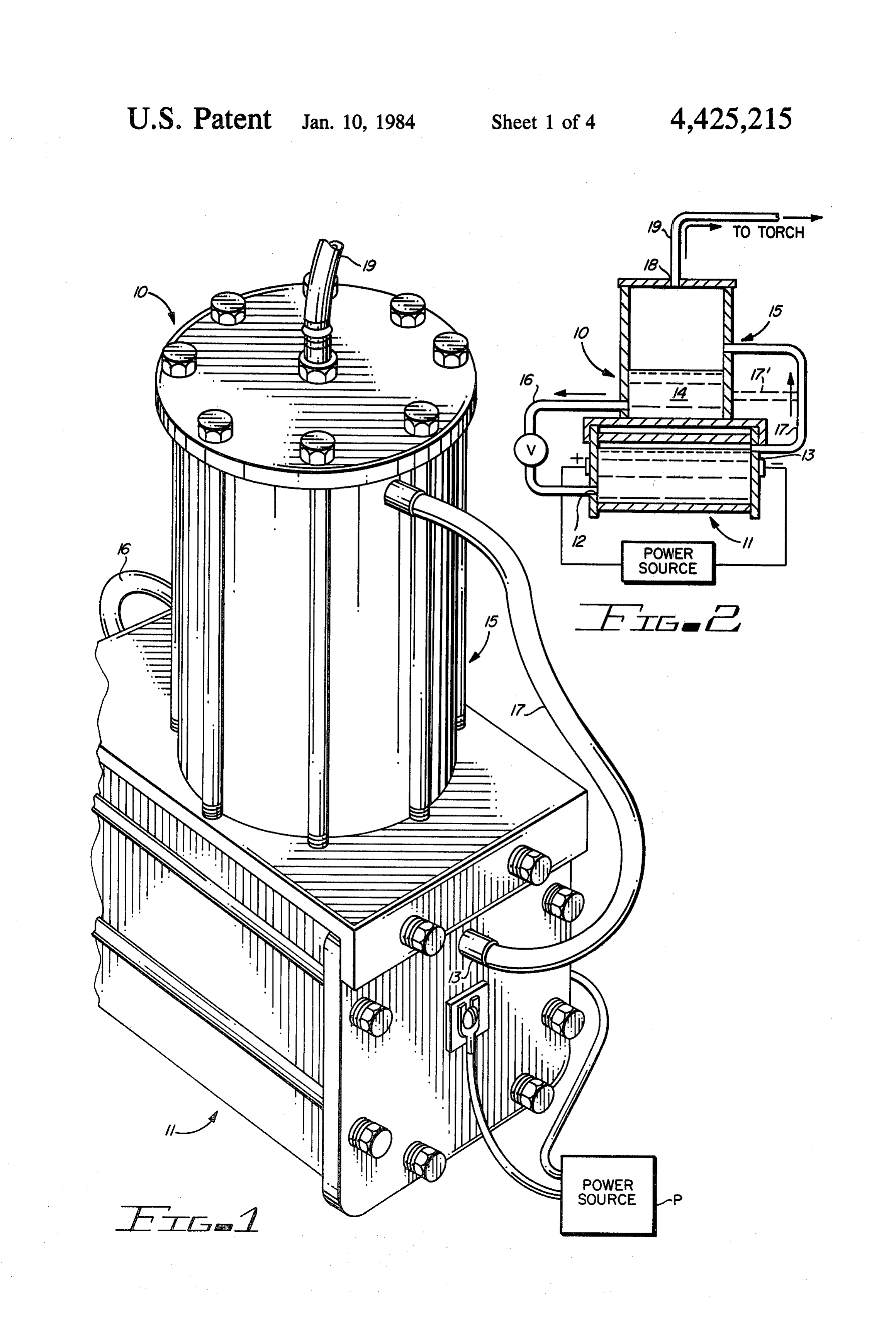
The present invention may be more readily described bly for use in multi-cell electrolysis apparatus. -: by reference to the accompanying drawings, in which: U.S. Pat. No. 4,124,480 describes a bipolar cell for use FIG. 1 is a partial perspective view of an improved primarily in the manufacture of sodium hypochlorite gas generatofembodying the invention; ; ; , ,
comprising 4,339,324of discloses multiplicity electrolytica gas cellsgenerator arranged 65 generator
FIG. 2 is a simplified functional diagram of the gas
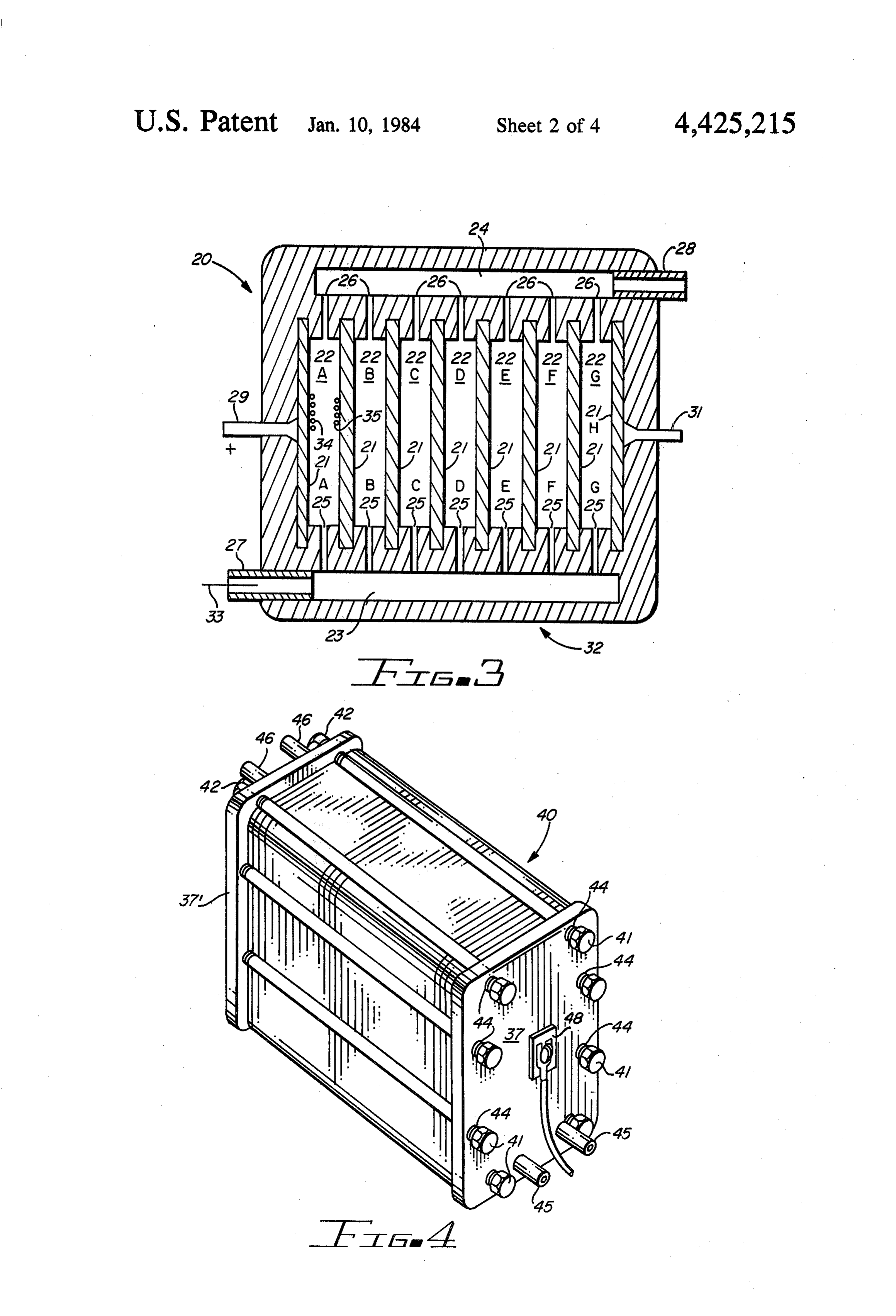
to accommodate a series current path, parallel electro FIG.3 is a simplified functional diagram of the gas lytic flow and minimized leakage current paths, in a generator portion of the structure shown in FIG. 1;
Page 7
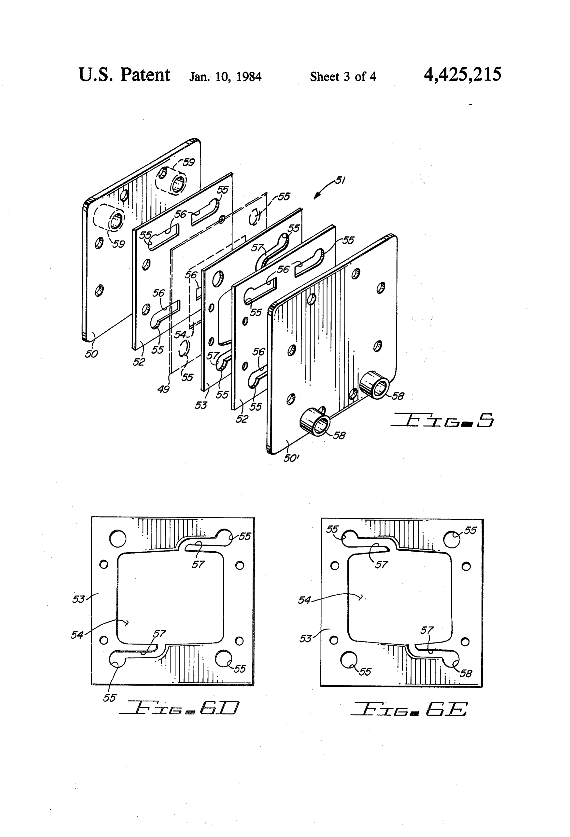
FIG. 4 is a perspective view of a discrete gas genera is delivered to all the chambers at the same pressure and tor; that the flow rate through all the chambers is the same. FIG. 5 is a partial exploded view of plates of a single Electric current flow is from the positive terminal 29 cell gas generator embodying the invention; to electrode 21A, through the electrolyte in chamber FIG. 6A is a partial view of the plates of a discrete 22A to electrode 21B, from electrode 21B through gas generator employing the plates shown in FIG. 5; chamber 22B to electrode 21C, through chamber 22C to and electrode 21D, through chamber 22D to electrode 21E, FIGS. 6B-6E are plan views of the various plates through chamber 22E to electrode 21F through cham shown in FIGS. 5 and 6A. ber 22F to electrode. 21G, through chamber 22G to O electrode 21H to negative terminal 31. The electrical
DESCRIPTION OF THE PREFERRED conductivity of the electrodes 21A-21H is high so that EMBODIMENT the potential difference between adjacent electrodes Referring more particularly to the drawings by char 21A and 21B, 21B and 21C, etc. is uniform over their mutually confronting surfaces. Current density from acters of reference, FIGS. 1 and 2 disclose a gas genera 15 electrode tor assembly 10 comprising an electrolysis chamber or to electrode through the intervening electro generator 11 having inlet and outlet ports 12 and 13, lyte is very uniform because the electrolyte is equally respectively. The inlet port 12 comprising one or two available to each electrode.
port openings, is supplied with electrolyte 14 from a Within each of the chambers 22A-22G, current flows tank 15 mounted above chamber 11 through a pipe line 20 from the more positive electrode to the more negative 16 connected to tank 15 near its bottom. The outlet port electrode. Thus, the face of the plate electrode from 13 comprising one or more port openings of chamber 11 which the current flows serves as the anode for that is connected by means of a pipe line 17 to tank 15 at a chamber while the face of the other juxtapositioned plate electrode to which the current flows becomes the suitable point in the tank. An outlet port 18 at the top of cathode.
tank 15 is connected by means of a pipe line 19 to a 25 the electrode It will be recognized that the opposite face of suitable torch (not shown), Chamber 11 is electrically serving as a cathode for chamber 22A connected across a suitable source of power P as shown serves as the anode for chamber 22B. The electrode 21B and the electrodes 21C-21G are thus known as bipolar in FIGS. 1 and 2.
FIG. 3 discloses a simplified diagram of an electroly electrodes, and the each having one face employed as an anode opposite face as a cathode. Within each cham sis chamber or polycell gas generator 20 functional in gas generator assembly 10 and comprising parallel, 30 ber the current flowing from anode to cathode results in the generation of oxygen and hydrogen, the oxygen 34 spaced apart plate electrodes 21A-21H, electrolysis collecting at the anode and the hydrogen 35 collecting chambers 22A-22G, an electrolyte inlet manifold 23, a at the cathode are swept out of the chamber mainly by gas and electrolyte outlet manifold 24, inlet ports 25, gravity, assisted by the electrolyte flowing through the outlet ports 26, an electrolyte supply port 27, a gas and 35 chamber, the gas and electrolyte mixture passing electrolyte delivery port 28, a positive terminal 29 and a through the outlet port 26 of each chamber into the negative terminal 31. Generator 20 is enclosed in a outlet manifold 24 and thence through outlet port 28 to sealed and electrically insulated housing 32 forming a a collection chamber or tank (as shown in FIGS. 1 and cavity within which the chambers 22A-22G are 2). + formed. Gas generator 40 of FIG. 4 constitutes another em In the particular implementation of generator 20 that bodiment of the invention and comprises a number of is of primary interest to this invention, the generator is flat or planar elements stacked together between end employed in the electrolysis of water for the generation covers or plates 37, 37" and secured as a unit by means of oxyhydrogen gas. The electrolyte employed can be a of bolts 41 and nuts 42.
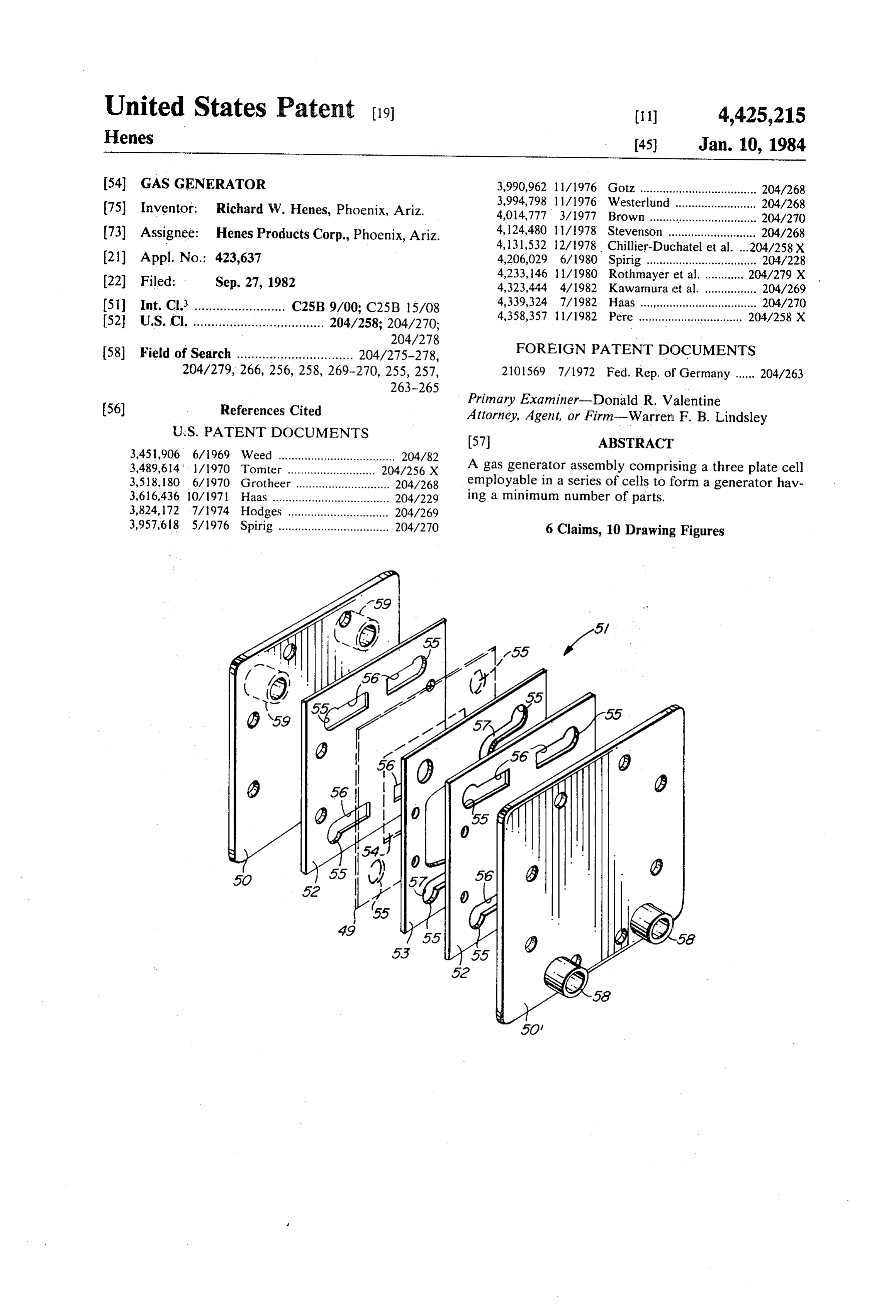
solution of potassium hydroxide (KOH) and distilled 45 End covers 37 and 37 comprise rectangular plates water, the potassium hydroxide being employed to pro molded from nylon or similar electrically insulating vide electrical conductivity. The electrodes 21A-21H material that is impervious to moisture. Holes provided are flat rectangular plates which may be made from about its periphery are provided to receive bolts 41. At nickel sheet stock. each end, two electrolyte (or gas and electrolyte) inlet In the operation of generator 20, electrolyte 33 enters 50 or outlet ports 45 and 46 are provided although in some port 27 and fills inlet manifold 23. From manifold 23, embodiments only one port at each end may be pro the electrolyte enters chambers 22A-22G via the inlet vided, the ports 45 and 46 being hollow tubular and/or ports 25, filling chambers 22A-22G and then passes out cylindrical configurations with their central openings through the outlet ports 26 into the outlet manifold 24 providing passageways through covers 37, 37". A screw from which it is finally exhausted through port 28. It 55 terminal 48 is provided at the center of each cover with will be immediately recognized that the chambers the terminal providing a conductive path through the 22A-22G with their inlet ports 25 and their outlet ports cover to a contact button (not shown) on the opposite 26 constitute parallel flow paths between the inlet mani side thereof and also providing a means for connection fold 23 and the outlet manifold 24. The manifolds 23 and to the positive or negative terminal of the power supply 24 are sufficiently large in cross-section to assure mini 60 P. Two such covers are employed in generator 40, one mal pressure drops along their lengths. In addition, the on each end of the stacked planar elements. entry port 27 is located at the bottom of generator 20 FIG. 5, excluding the insulating plate 49 shown in while the delivery port 28 is located at the top of gener dash lines, illustrates a single cell electrode assembly of ator 20 so that the total path length traversed by the a particular cell configuration for a gas generator which electrolyte passing through any one of the several 65 may be arranged in multiples between the ends or cover chambers 22A-22G is the same as that traversed by the . : plates 50, 50' to form a gas generator. 51. electrolyte passing through any of the remaining cham Each cell assembly of this gas generator comprises an bers. These precautions help assure that the electrolyte electrode plate 52, shown more clearly in FIG. 6C,
Page 8
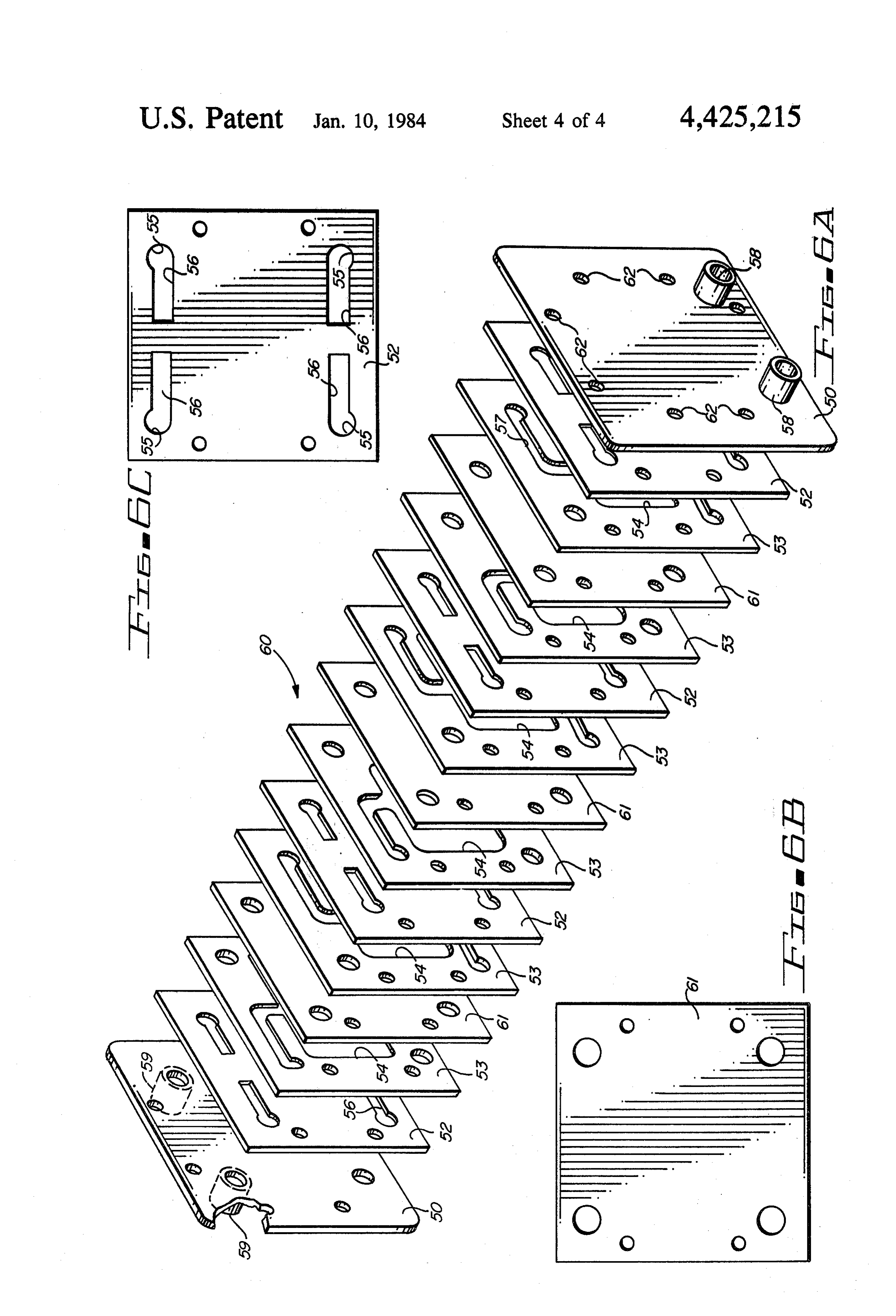
positioned at each end of the cell assembly which is FIG. 6A illustrates an electrode assembly of the par formed of a thin conductive plate of nickel when used in ticular cell configuration shown in FIG. 5 for a discrete a oxyhydrogen gas generator. An insulating spacer gas generator which may be arranged in multiples be element or plate 53 comprising a frame, as shown in tween the end plates 50 and 50' which cells when FIGS. 6D and 6E encircling an opening 54 extending stacked and held together by bolts and nuts 41 and 42 of therethrough is mounted between the pair of electrodes FIG. 4 form a discrete gas generator 51. 52 in an aligned parallel array. Each of the electrodes Each cell assembly of this discrete gas generator 52, spacer element 53 and cover plates 50, 50' have comprises an oxygen generating cell and a hydrogen opposed end portions. Each electrode plate and spacer generating cell. An assembled gas generator comprises element is provided with one or a pair of spaced aper O an electrode plate 52, as shown in FIG. 6C, positioned tures 55 extending therethrough in each end portion at each end of a cell assembly which is formed of nickel thereof with similarly positioned apertures in each end when used in an oxyhydrogen gas generator. Terminals portion of the electrode plates and spacer elements at the ends of the stacked assembly may serve as termi being interconnected in axial alignment. Each aperture 5 nals for the gas generator as shown in FIG. 4. 55 in each electrode plate is provided with a slot 56 Each cell assembly in gas generator 60 comprises a extending from that aperture toward the center of the thin conductive solid plate 52, insulating picture frame plate and in line with any other aperture of the elec like spacer element or plate 53 of the type shown in trode plate at that end of the plate. FIGS. 6D and 6E, having an enclosed opening 54, sepa One aperture 55 at each end of the element is pro 20 rated by a separator element or plate 61, shown in FIG. vided with a slot 57 extending laterally from the aper 6B, which may be formed of cellophane. Each sequen tially arranged plate 53 is arranged in a reverse image ture toward a center line of the frame and communicat ing with opening 54 in the frame. - -position or one rotated 180 degrees on its vertical axis
It should be noted that slots 56 at each end of elec from the preceding plate 53. trode plates 52 are juxtapositioned to and overlap any 25 The outer dimension of plate 52 and the other plates slots 57 that appear in juxtapositioned spacer plates 53. of the cell assemblies are substantially identical and all The aligned apertures 55 of electrode plates 52 and employ mating substantially identically spaced and po spacer plate 53 at the lower end portions thereof are sitioned holes or apertures 55, which form gas and elec trolyte passageways. Identically positioned bolt holes connected through inlet ports 58 in cover plate 50' to a 62 provided in end plates 50, 50' receive bolts 41 in the source of electrolyte which flows through these inlet 30 manner shown in FIG. 4 for holding the assembly of ports and apertures into the gas generator.
Electrolyte flowing into inlet port 58 at the left bot plates together.
As shown in FIGS. 6A and 6E, each of plates 52 are tom corner of cover plate 50' flows through aperture 55 provided in plate 52 and into aperture 55 in plate 53 and through thereof from with narrow slots 56, one extending inwardly a different positioned hole 55 formed slot 57 connected thereto and into the opening 54 in the 35 therein and along frame formed by plate 53. After passing through open the top and bottom edges of the plate ing 54, which is closed on both sides by the flat adjacent ending just short of the other hole at the opposite sides surfaces of adjacent plates 52, the electrolyte and gases of the plate. Slots 56 serve as gas and electrolyte pas generated in this passageway pass through slot 57 and sageways in the assembled gas generator 60. aperture 55 in the top of spacer plate 53 and through In gas generator 60, a plurality of cell assemblies are arranged in an axial arrangement one sequentially fol outlet ports. 59 to a storage tank or torch (not shown). lowing the other. Reading from left to right, the assem If desired, an insulating plate or frame, such as plate bly of gas generator 51 comprises an electrode plate 52, 49 formed of the same material as plate 53 and having a spacer plate 53, cellophane separator membrane 61, substantially matching opening 54 therein shown in spacer plate 53 which is a reverse image of the previ dash lines in FIG. 5, may be utilized to block each side 45 ously mentioned of the gas generator from passing electric current from plate 53 which isspacer a plate, electrode plate 52, spacer reverse image of the previous plate the first electrode directly to a later electrode, bypass 53, cellophane separator membrane 61, spacer plate 53 ing one or more intervening electrodes. It should be arranged as a reverse image of the previous plate 53, noted that plate 49 is only used in a multi-cell sequence electrode plate 52, spacer plate 53, arranged as a reverse even though it is shown for purposes of illustration in SO image of the previous plate 53, cellophane separator FIG. 5 in a single embodiment. With plate 49 in place, membrane 61, spacer plate 53 which is a reverse image electrolyte will pass through only the inlet port 58 of the previous spacer plate and electrode plate 52. shown on the left side of cover plate 50', through aper Each additional cell assembly of plates 52, 53 and 61 ture 55 in plate 52, aperture 55 and slot 57 in plate 53, used in gas generator. 60 are repetition of the plates just opening 54 in plate 53, slot 57 and aperture 55 at the top 55 described in the continuous assembly of cell assemblies of plate 53, aperture 55 in plate 49, aperture 55 in the left to right in the gas generator plate assembly shown plate 52 to the left of plate 49, as shown in FIG. 5, and in FIG. 6A.
out of outlet port 59 at the top right side of cover plate The interrelationship between the holes 55 and slots 50. Plate 49 merely serves to insulate one cell from 56 in plates 52 and slots 57 in plates 53, cooperate to another by closing and forming a barrier between slots form the inlet and outlet ports and manifolds for the 56 and slots 57 of the plates in question. An alternate electrolyte and generator gas. As shown in FIG. 6A, method of accomplishing this is to flip-flop plate 53 for the holes 55 of the plates 52, 53 and 61 are mutually each cell in a generator configuration, but this arrange aligned to form common passageways running perpen ment then necessitates using both inlet ports 58 at one dicularly through the stacked plates. The four holes 55 end and both outlet ports 59 at the other end. The use of 65 in each plate form four passageways through the plate 49 allows use of only one inlet port 58 and one stacked assembly.
outlet port 59, and plates 53.are "then not. flip-flopped for The electrolyte (H2O.--KOH) enters the two pas each cell. ... . . . . . "...i. sages 58 at the bottom right end of the gas generator 60
Page 9
shown in FIG. 6A formed by the aligned holes 55 of the The ports 58 of the right cover 50" are preferably posi plates 52, 53 and 61. From these two passages, the elec tioned at the bottom of the assembly, as shown in FIG. trolyte follows slots 56 of electrode plates 52 to indenta 6A, while the ports 59 of the rear cover 50 are posi tions or slots 57 of spacer plates 53. Electrolyte reach tioned at the top (or vice versa), for gravity reasons. ing indentation or slots 57 of plates 53 on the right side 5 With plates 52, 53 and 61 and the front and rear cov of plate 61, as shown in FIG. 6A at the right end thereof ers or plates 50", 50 stacked and aligned, as just de flows upward out of slots 57 into apertures 55 along the scribed, bolts 41 are passed through holes 62 and are far surface of the cell assembly and all like cells dis secured in place by means of nuts 42. When the nuts are charging electrolyte and gases into this passageway properly tightened, a sealed assembly is achieved in while electrolyte emerging from indentation or slots 57 10 which the frames of the elements are tightly com of plate 53 to the left of plate 61, rises along the near pressed together so that the electrolyte is effectively surface of electrode plate 52 positioned to the left of contained. The containment of the electrolyte may, of plate 61. If current I flows into electrode plate 52 from course, be enhanced by prior coating of the mating cover plate 50' having an electrode 48 thereon into plate surfaces with a joint compound or sealing material. 52 in FIG. 6A, it becomes a cathode and the near face 15 Although but a few embodiments of the invention of electrode plate 52 to the left of plate 53 becomes an have been illustrated and described, it will be apparent anode. The gas generated at the far surface of plate 52 to to those skilled in the art that various changes and modi the right of plate 53 is hydrogen and the gas generated fications may be made therein without departing from at the near surface of plate 52 to the left of plate 53 is the spirit of the invention or from the scope of the ap oxygen. Both gases move upward along with the flow 20 pended claims.
of the electrolyte, the hydrogen finds its way into slot What is claimed is:
57 of the spacer plate 53 to the right of plate 61 follow 1. A gas generator assembly comprising in combina ing slot 57 into the passageway formed by the aligned tion:
holes 55 in the upper right-hand corner of the gas gener ator, and the oxygen generated on the near surface of 25 a pair of metal electrodes positioned in an aligned parallel array, plate 52 to the left of plate 61 flows into indentation an insulating spacer element comprising a frame en slots 57 of plate 53 to the left of plate 52 through slot 57 circling an opening extending therethrough in plate 53 into the passageway formed by the aligned mounted between said pair of electrodes in said holes 55 in the upper left-hand corner of the gas genera aligned parallel array, tor. 30
Slots 57 thus constitute the inlet and outlet ports cover plates mounted at each end of the assembly of corresponding to ports 25 and 26 of gas generator 20 of said electrodes and spacer element, FIG. 3. The long and narrow proportions of slots 57 each of said electrodes, spacer element and cover afford the high electrical impedance needed for the inlet plates having opposed end portions, and outlet ports to assure minimization of leakage cur 35 saidvided electrodes and spacer element each being pro with at least one aperture extending through rents.
The cellophane separator elements 61, shown in FIG. each of said end portions with apertures in like end 6A positioned between adjacent plates 53, readily pass portions being interconnected in axial alignment, the ionic current flow I, but block the lateral flow of the said frame of said spacer element being provided with generated gases. Because the successive spacer plates 53 a first slot extending laterally from said aperture in are reversed to stagger the positions of the indentations each of its end portions toward a center line of said or notches 57, the oxygen is consistently diverted to the frame and communicating with said opening in said left and the hydrogen is diverted to the right side of the frame, gas generator as described. With the aid of the cello a second slot arranged in each of said end portions of phane separator elements 61, the generated oxygen and 45 said electrodes extending from said aperture hydrogen gases are separated and delivered separately toward the center line of said electrodes, from gas generator 60. said second slot in each of said end portions of the The flow of electrolyte within the window openings electrodes being juxapositioned to and overlapping 54 of plates 53 is in the form of an electrolyte sheet or said first slot in said element at each end of said bodies of fluid which are quite narrow in width, the 50 saidelectrodes, and aligned apertures of said electrodes and said thickness being equal to the thickness of these plates which may be readily made as thin as desired. Close spacer element in common end portions at one end electrode spacing is thus achieved in this assembly with of said electrodes and spacer element being con out exposure to problems involving close mechanical nectable to a source of electrolyte which flows tolerances. Because the adjacent electrodes 52 are 55 through these apertures, said second slot and asso closely spaced, the ionic path length is short which ciated first slot of said spacer element and into the promotes conductivity. Furthermore, the close elec opening in said spacer element between said elec trode spacing assures a maximum degree of contact trodes and out said second slot and the associated between the electrolyte circulated and the electrode first slot at the other of said common end portions surfaces where the gas is generated. Thus, highly effi 60 of said spacer element.
cient and effective gas production is achieved in an 2. A gas generator assembly comprising in combina assembly that inherently permits the separation of the tion: w oxygen and hydrogen gases. a pair of metal electrodes positioned in an aligned In a totally assembled generator 60, the elements are parallel array, stacked in the order shown in FIG. 6A. End covers or 65 an insulating spacer element comprising a frame en plates 50, 50' then are positioned one at each end of the circling an opening extending therethrough stack of plates with the holes 62 of covers or plates 50, mounted between said pair of electrodes in said 50' being aligned with their holes 62 receiving bolts 41. aligned parallel array,
Page 10
cover plates mounted at each end of the assembly of cent element in that'end portion of said electrode, said electrodes and spacer element, and . . . . . . . . . . . . . . . each of said electrodes, spacer element and cover the aligned apertures in one end portion of said elec plates having opposed end portions, trodes and spacer elements being connectable to a said electrodes and spacer element each being pro source of electrolyte which flows through these vided with a pair of spaced apertures extending apertures, the second slots of said electrodes and therethrough, one pair in each of said end portions associated first slots of said spacer elements into the with similarly positioned apertures in like end por - opening in said spacer-elements between said elec tions being interconnected in axial alignment, "trodes in a parallel simultaneous manner and out said frame of said spacerelement being provided with ::: the first slots and associated second slots of the a first slot extending laterally from one of said electrodes at the other end portion of said elec apertures in each of its end portions toward a cen trodes, and spacer elements. terline of said frame and communicating with said 5, A gas generator assenbly comprising in combina
a pair of second slots arranged in each of said end 15 tion: . . . . . . . .. . portions of said electrodes extending from the . . . ; parallei array, ... . . . . . . . positioned a pair of flat metal electrodes
in an aligned other of said apertures toward the center line of a pair of insulating spacer elements comprising frames said electrodes, encirclings openings, extending, therethrough one of said second slots in each of said end portions of said electrodes being juxtapositioned to and over- 20 mounted, between said, pair of electrodes in said lapping a first slot in said element, and aligned parallel array, said aligned apertures of said electrodes and said a semipermeable membrane element comprising a spacer element in common end portions at one end substantial gas barrier mounted between said pair of said electrodes and spacer element being con of insulating spacer elements, nectable to a source of electrolyte which flows 25 each of said electrodes, spacer elements and mem through these apertures, a second slot and associ brane element having opposed end portions, ated first slot of said spacer element and into the said electrodes, spacer elements and membrane ele opening in said spacer element between said elec ment each being provided with a pair of spaced trodes and out said second slot and the associated apertures extending therethrough in each of said first slot at the other of said common end portions 30 end portions with similarly positioned apertures in of said spacer element. like end portions being interconnected in axial 3. The gas generator assembly set forth in claim 2 in alignment, further combination with: a pair of first slots arranged in said end portions of an insulating frame mounted between said electrodes, said electrodes extending from said apertures said insulating frame having an aperture at each end 35 toward the center of said electrodes, in alignment with said apertures in said end por each frame of said spacer elements being provided tions of said electrodes and said spacer elements. with a second slot extending laterally from one of 4. A polycell gas generator assembly comprising in said apertures in each of said end portions of said combination: elements toward the center of said frame and com a plurality of metal electrodes positioned in an 40 municating with said opening in said frame, aligned parallel array, one of said first slots in each of said end portions of a plurality of insulating spacer elements, each come said electrodes being juxtapositioned to and over prising a frame encircling an opening extending lapping a second slot in said spacer element, and therethrough, with at least one element mounted each spacer element being a reverse image of the next between each pair of adjacent electrodes in said 45 spacer element in the array, aligned parallel array, said aligned apertures of said electrodes, said spacer cover plates mounted at each end of the assembly of elements and said membrane element in common said electrodes and spacer elements, end portions at one end thereof being connectable each of said electrodes, spacer elements and cover to a source of electrolyte which flows through plates having opposed end portions, 50 these apertures, a first slot and associated second means for clamping the plurality of electrodes, spacer slot of each said spacer element and into the open elements and cover plates together so as to provide ing in each said spacer element between one of said a plurality of cells, one between each pair of adja electrodes and said membrane element and out said cent electrodes, first slot and second slot at the other of said end said electrodes and spacer elements each being pro 55 portions of each said spacer element, vided with a pair of spaced apertures extending therethrough in each of said end portions thereof, said aligned apertures of said electrodes, said spacer each frame of said elements being provided with first elements and said membrane element in common slots extending from said apertures at opposite end end portions at one end thereof serving as gas dis portions of said elements toward a center line of 60 charge ports.
said frame and communicating with said opening in 6. A gas generator assembly comprising in combina said frame, tion:
a pair of second slots arranged in each electrode in a plurality of flat metal electrodes positioned in an each end portion thereof with each second slot aligned parallel array, extending laterally from each aperture toward the 65 a plurality of insulating spacer elements comprising center line of said frame, one of said second slots in frames encircling openings extending therethrough each end portion of the electrode being juxtaposi mounted between each pair of electrodes in said tioned to and overlapping said first slot in an adja aligned parallel array,
Page 11
a semipermeable membrane element comprising a one of said first slots in each of said end portions of substantial gas barrier mounted between each pair said electrodes being juxtapositioned to and over of insulating spacer elements, lapping a second slot in each spacer element, and each of said electrodes, spacer elements and mem 5 each spacer element being a reverse image of the next brane elements having opposed end portions, spacer element in the array, said electrodes, spacer elements and membrane ele said aligned apertures of said electrodes, said spacer ments each being provided with a pair of spaced elements and said membrane elements in common apertures extending therethrough in each of said end portions at one end thereof being connectable end portions with similarly positioned apertures in O to a source of electrolyte which flows through like end portions being interconnected in axial these apertures, a first slot and associated second alignment, slot of each said spacer element and into the open a pair of first slots arranged in said end portions of ing in each said spacer element between one of said said electrodes extending from said apertures electrodes and said membrane elements and out said first slot and second slot at the other of said toward the center of said electrodes, 15 end portions of each said spacer elements, each frame of said spacer elements being provided said aligned apertures of said electrodes, said spacer with a second slot extending laterally from one of elements and said membrane elements in common said apertures in each of said end portions of said end portions at one end thereof serving as gas dis elements toward the center of said frame and com charge ports.
municating with said opening in said frame, 20 is k + k is
Provenance
- Collection
- Cited prior art
- Original PDF
- patentimages.storage.googleapis.com →
- Filed
- 1982-09-27
- Pages
- 11
- Method
- pdftotext (the PDF's own text layer) + pdftoppm 300dpi page scans
- Source
- Google Patents bibliographic record
- Granted
- 1984-01-10
- Inventors
- Richard W. Henes; Henes Products Corp
- Transcribed from
- patentimages.storage.googleapis.com →