patent · US2386978
Gas generating burner
16 October 1945
Page 1
Drawing sheet — no readable text.
Page 2
Patented Oct. 16, 1945
UNITED STATES PATENT OFFICE
GAS GENERATING BURNER
Charles L. Ruhl, Dallas, Tex.
Application October 20, 1941, Serial No. 415,805
1 Claim.
This invention relates to the art of gas generation and consumption. In a more specific sense; it relates to gas-burners, so called.
The object of the invention is to control those types of gases which are so highly flexible that, if not controlled, will, because of their speed and flexibility, cause the flame therefrom to blow itself out when reaching the zone of ignition because of either a predominance of air or of gas.
Manufactured gas has about five hundred and
fifty British thermal! units per cubic foot, while.
natural gas has about one thousand, and the more highly flexible liquified gases, such as butane or iso-butane, average around three thou- -sand or better.
The gas-burners of the prior art do not provide.
for handling these more high flexible and liquifled gases, nor is there a teaching in the prior art that any of the burners of the art can be re-adjusted or converted into use for these more highly flexible gases, of which butane or isobutane are examples.
The problem, therefore, is the proper provision of a device for handling these highly flexible - liquified gases so that the flame will not blow itself out when the gas and the air have been balanced and proportioned in an elongated mixing tube, in the form of an air and gas way or run, and when the mixture is balanced to the
exclusion of the predominance of gas or air and *
forced to speed through the run, expanding meanwhile, so that the product for ignition and combustion will be substantially perfect and useful.
Provision has been made whereby the more highly flexible and liquified gases are treated during flowage between the point of release from the valve-spud and the point where it enters the zone of ignition, so that, during this treatment, the gas and the air are not only balanced, but expanded while being balanced. :
In the prior art when gas is released from the valve-spud, its behavior is then disregarded, as far as gas and air balance is concerned, so long as combustion is attained accompanied by air or gas excess, usually becoming known by odor or smut, and since the prior art teaches only those
‘types of burners for. the less flexible gases, the matter of holding the flame against blowing out is not necessary to observe, because its pressure is as low as eight ounces.
The only instrumentalities that have been provided in the art are the mixing shutters, which contro] the amount of air to be added to the gas to induce normal combustion, together with many theoretical structural additions, such as bafiles.
These disclosures, if applied to the use of the more highly flexible and liquified gases, would cause the flame to blow itself out, for until the air and the gas are mixed, and the mixture is allowed to generate a balance and an expansion speed prior to combustion, the expanded mix will not sufficiently rarefy to allow all of the molecules, both of the air and the gas, to blend and allow of proper ignition, but either a predominance of air or of gas will cause the flame to blow itself out. .
To this end, therefore, means are provided with and by which this highly flexible liquified gas, such, for instance, as butane or iso-butane may be released at the valve-spud, and allowed first to flow into a conversion point, and then expand together with the air, this expansion so rarefying the mix that by the time it reaches the zone of combustion, there is a balanced mix and not a predominance of either gas or air.
The disclosure herewith indicates a device in which it is designed to utilize essentially all of the units of the gas, even under the speed with which the highly flexible liquified gases flow, vaporize and mix.
On the drawing, forming a part of this specification, there is a mixing chamber; said mixing chamber has an interior cyma recta and cyma reversa formation or passages which are round in cross section and the curves result in constricted passages that control the flow of gas and air on its way to the burner, and leading away from this chamber is a, gas and an air mixing tube which constitutes an elongated gas and air way run, along which both the gas and the air proceed and speed. As both the gas and the air expand, a fusion of gas and air initiates, so that by the time the mixture of the gas and the air reaches the zone of combustion, neither the air nor the gas will predominate; but the mixture speeds into place for use, with a speed that not only renders the mix adapted for use, but renders it fully efficient for combustion, by merely cracking the valve. ,
On the drawing,
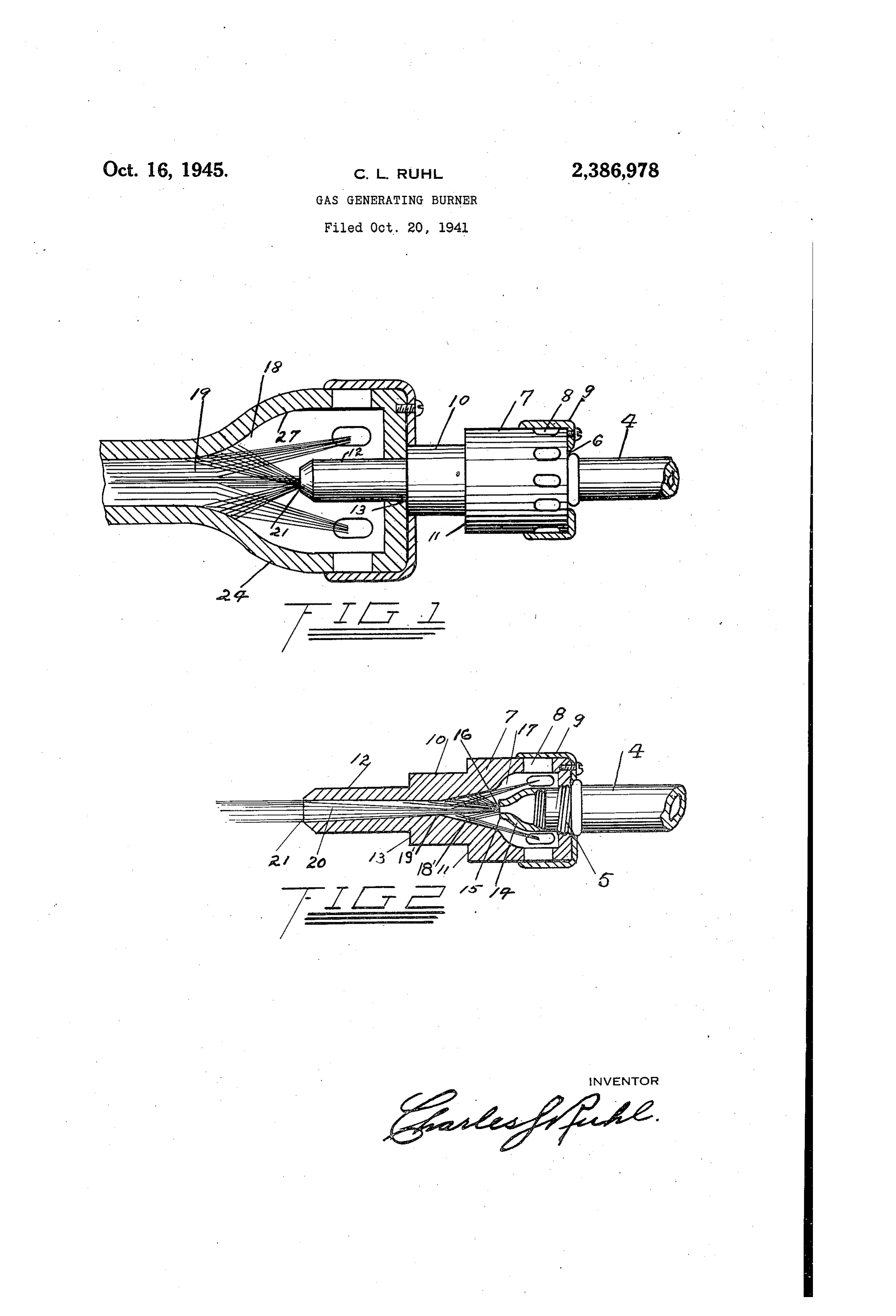
Figure 1 is a mixing device, comprehending the essentials of the invention, being both in elevation and in section.
Figure 2 is a sectional view of a portion of the device of Figure 1.
In these several views, similar characters of reference will indicate similar parts.
The branch 4 of a gas-valve is exteriorly screw-threaded at 5 for entry in to a screwthreaded opening in the frontal plate 6 of a mix-
Page 3
ing head 7, which is provided with radial ports 8,
which are controlled by a revolving shutter 8.
From this mixing head 7 extends a neck [0 between which and the head 7 isa shoulder ff. Extending from this neck 10 is a second neck 12, between which and the neck 10 is a shoulder 13. The purpose of. these shoulders is that the device may be used in conjunction with units having varied sized intake openings in the mixers.
A small mixer with a small opening will allow the mixing tube to enter only to the shoulder 43, while a mixer with a larger opening will allow the smaller shoulder to pass in, and the larger neck may enter the opening up to the shoulder if. This provides for the proper adjustment of the outlet 21, with reference to the wall 27 of the mixing head of any size, thus insuring the proper distribution of gas and air within the mixing head 24,
The branch 4 may be exteriorly screw-threaded to receive a spud 44, which terminates in a nose {5, which, on its interior, is a cyma recta and cyma reversa formation or passages which are round in cross section and the curves result in constricted passages, and the cyma reversa wall tapers to an orifice 16.
This spud enters axially into the chamber {17 of the mixing-head 7. Remote from its frontal wall 6, the inner wall of the mixing head is of a cyma recta and a cyma reversa formation and constitutes an inner run-way for the mixing-cham-
Beyond the mixing-chamber i7, the cyma-re-
versa, wall or run-way reduces into a pressure vent 18’ and continues to reduce until it reaches a vital conversion point 19’. The head has a neck portion 10 and a reduced extension {2 leading from said portion and constituting a mixing tube. The said conversion point is in. the neck portion {@ and forms the front end of an elongated diverging gas and air passageway 20 leading to the
_ It will be noticed that as the gas flows from the spud f4, and compresses into the chamber 18’, the speed of flow will create an expansion and a vacuum in 20, and this will prevent back firing which woyld otherwise take place, because, if the expansion and vacuum did not. take place it would cause a back pressure and drive the gas out through the intake ports.
It is the purpose, at this point, to teach that the elongated mixing tube, will be greater in diameter at the outlet 2f than at the conversion point 19’, and that the dimensional ratio between these two points will be such as to make passage 20 and conversion point {9’ a speed-developingpassage,
In view of the fact that the highly flexible liquified gases expand with rapidity, when subjected to release and speed, the dimensional ratio between the conversion point #8’ and the outlet 21 will be wrought out with considerable precision. :
In practice it will be desirable to so reduce the expansion of the:mix by providing the passageway 20 with a very small variance between the conversion point 19’ and the outlet. Perhaps (while the drawing is exaggerated for emphasis) but a few ten-thousandths of an inch will suffice.
When the highly flexible liquefied gas issues from the valve-spud opening 16, the speed of the gas-flow will draw into its column the air from the ports 8. Rarefaction and expansion both of the gas and of the air molecules now obtain, and the expansion, due to the formation of the mixing head internal wall, will be subjected to a progressive contraction as-it moves along this restricting wall-to the conversion point 19’. At this point the velocity is high, and the mix is ready to pass into and through passage 20 with considerable speed, while expansion obtains to rarefy the projecting flow as emitted at the « mouth 21! as a balanced mix,
This expansion of the mix, in contrast to the previous progressive contraction toward and at the conversion point {9’, now equally as well progressively expands away from the conversion point until the mix is perfectly balanced without the predominance of either the gas or the air.
It is now obvious that by the provision of an elongated passage, leading off from a point or zone of high compression of the gas and the air, that, with a high speed and flexible liquified gas such as butane or iso-butane, the admixture is controlled dually by compression and expansion, and by expansion and speed. .
The speed drives the balanced admixture to progressive contraction, and then through expansion so that there is a.complete fusion of the gas and air, so that when the admixture reaches the point of ignition, it will burn because it is thoroughly balanced, with no excess either of gas or air to choke or blow out.
The words “flexible” and “flexibility” are employed throughout the specification for the purpose of describing the action of the liquified gases, such as butane and the like, which vaporize very rapidly and ‘expand in accordance with the amount of air permitted to mix with the vaporized gas. The uses of liquified gases have been limited due to the difficulty of securing the proper proportions of gas and air. This is overcome by the present invention, thereby affording its application greater flexibility or uses.
Having set forth the invention, I claim:
In a device as set forth, the combination with & first mixing head having an interior wall curved inwardly and then convexly in the direction of flow and forming a mixing chamber which is provided with orifices providing air ports, means for regulating said orifices, a gas supply means extending axially into said chamber to a position short of said convex portion, an extension leading from the mixing head having two channels, the first converging from the mixing chamber and the second expanding from the converging. channel to the outer end of said extension, the curved wall of the mixing chamber serving to intermix the gas and air before entering the channel where it is converged and then released through the expanding channel as a jet, a second mixing chamber having a wall curved corresponding to the curvature of the wall of the first named mixing chamber, said extension projecting into said second chamber to a position short of said convex portion whereby said jet enters said second mixing chamber. :
CHARLES L. RUHL.
Provenance
- Collection
- Cited prior art
- Original PDF
- patentimages.storage.googleapis.com →
- Filed
- 1941-10-20
- Pages
- 3
- Method
- pdftoppm 300dpi + tesseract 5 (eng)
- Source
- Google Patents bibliographic record
- Granted
- 1945-10-16
- Inventors
- Charles L Ruhl
- Transcribed from
- patentimages.storage.googleapis.com →