patent · US2701608
Burner
8 February 1955
Page 1
Drawing sheet — no readable text.
Page 2
Drawing sheet — no readable text.
Page 3
Drawing sheet — no readable text.
Page 4
United States Patent Office
Patented Feb. 8, 1955
BURNER
John A. Johnson, Stratford, Conn., assignor to Thermal Research and Engineering Corporation, Waltham, Mass., a corporation of Delaware
Application February 3, 1951, Serial No. 209,293
This invention relates to combustion, and more particularly combustion which is completed, under control, with high heat release in a chamber of limited size before utilization of the energy which is generated by the combustion. The invention is especially useful in its application to the combustion of oil, to which use, however, it is not restricted. . .
In some heating installations it is found to be of advantage to complete the combustion of the fuel in a cham-
ber where-it may be controlled before utilizing the energy ©
which the combustion generates. It is of importance, however, to keep such chamber at a minimum size, both for the purpose of facilitating control and for economy of space and materials. In order to employ a combustion chamber of minimum size, a high rate of heat release, rapid and continuous supply of fuel and air, and thor ough and intimate association of fuel and combustionsupporting air are imperative. Furthermore, simple and rugged mixer and burner design are of the. utmost importance, both from the standpoint of operation and that of maintenance.
When oil is burned as a dispersion in air it burns on the surface of the liquid droplets. Such droplets are partially cracked by the high temperature in a local absence of air, and the resulting carbon particles then burn as solids. Combustion of this character takes time, and if high heat release is required considerable space is necessgfy for completion of the combustion. By vaporizirfg the oil dispersion prior to combustion, it becomes possible to attain a rapid rate of heat release in a small chamber. :
I have now found it possible to construct a simple, relatively inexpensive unitary burner and mixer which eliminates parts heretofore considered indispensible. This novel burner makes possible the use of a combustion chamber of minimum size wherein combustion may be completed at a maximum rate of heat release before the generated energy is utilized.
According to the invention, a single chamber is unitarily formed with a mixing section and a combustion section in sequence, the. cross-section of the chamber being abruptly enlarged to provide a simple protecting shoulder in the combustion section behind which the flarne is held to assure continuous combustion therein. Where oil is employed it is:sprayed into the mixing section to disperse it into a column of air, moving therethrough, and the dispersed oil is pre-heated and vaporized in the mixing section by returning to that section a part of the burning gases from the combustion section. initial ignition, combustion does not take place in the mixing section.
The invention is shown by way of illustration in the accompanying drawings, wherein— ;
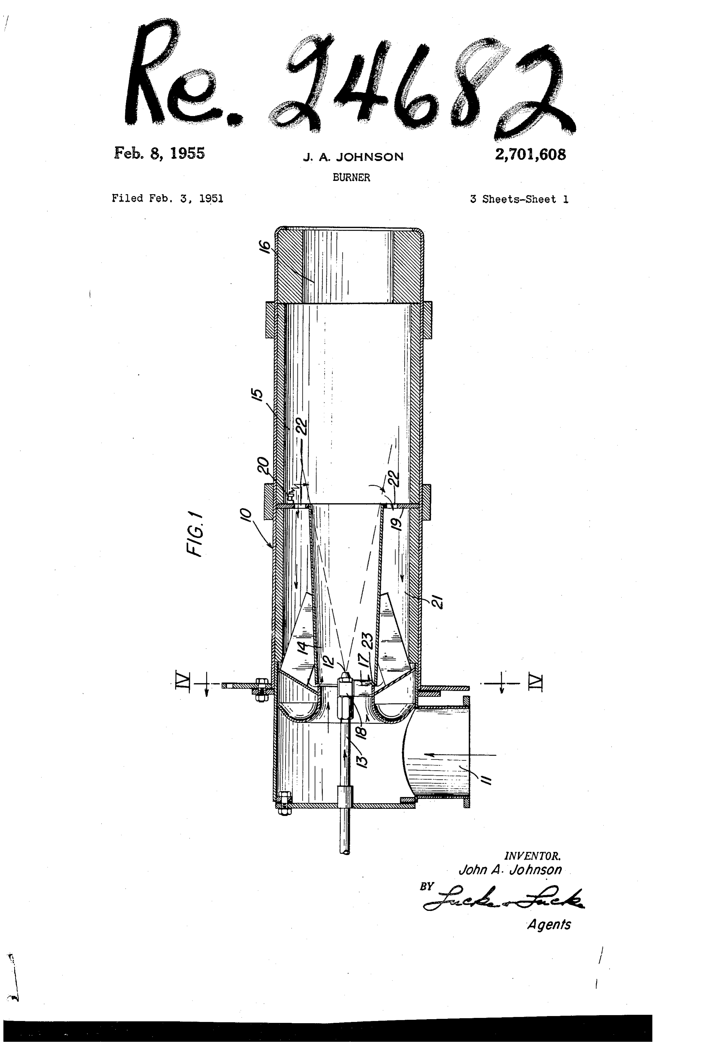
Fig. 1 is a longitudinal mid-section through a fluid fuel burner constructed and arranged according to the invention;
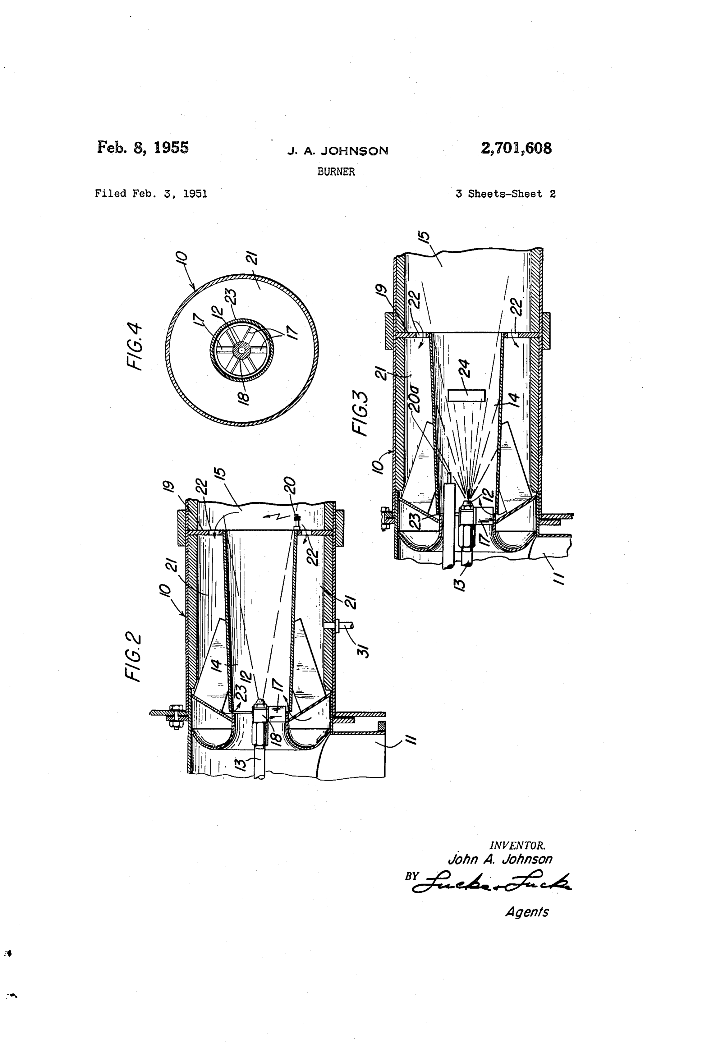
Fig. 2 is a broken:longitudinal mid-section through a differently arranged fluid fuel burner according to the invention; .
Fig. 3 is a broken longitudinal mid-section through a fluid fuel burner according to the. invention, which is still differently arranged;
Fig. 4 is a cross-section taken on the line IV—IV of
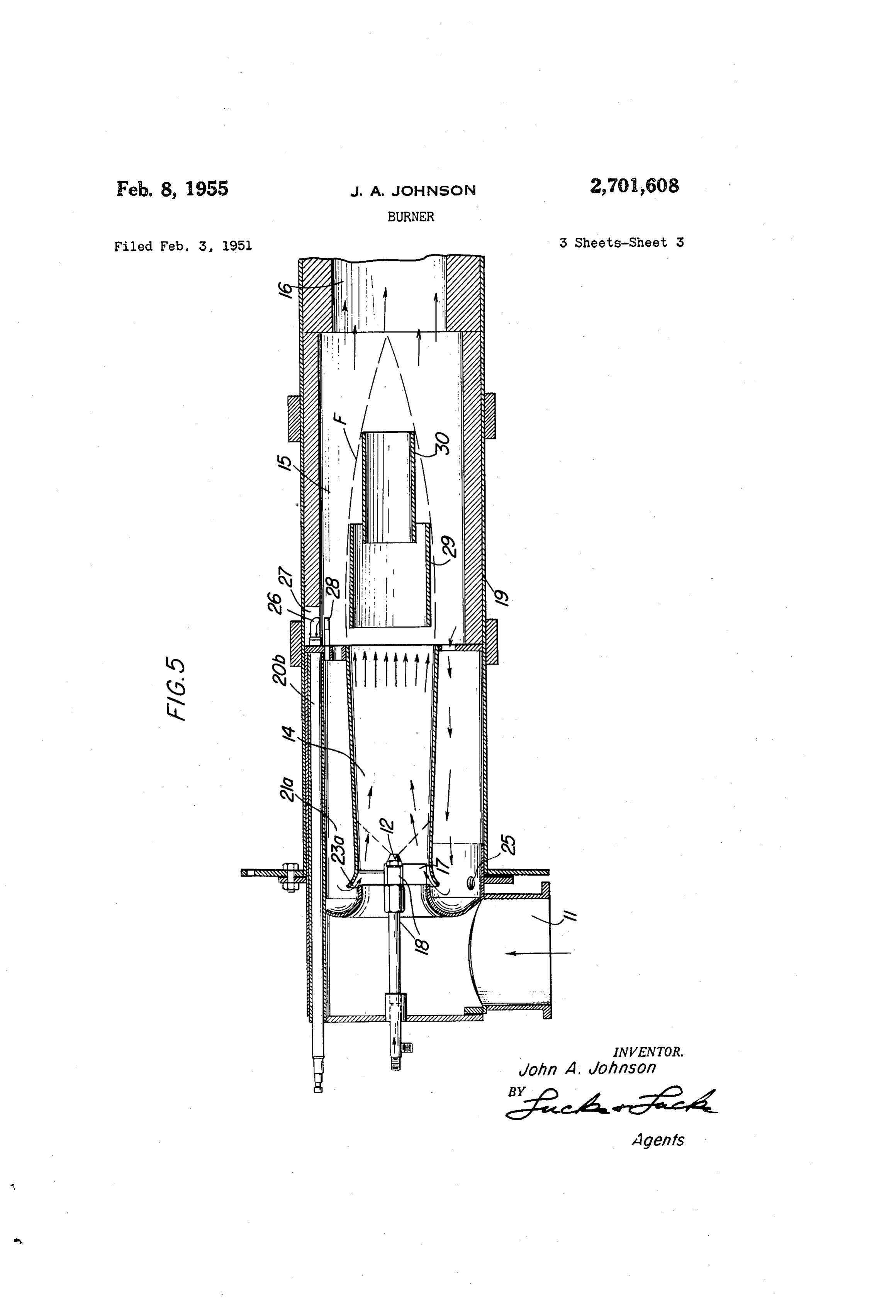
Fig. 5 is a longitudinal mid-section through a variant form of burner according to the invention. .
The embodiment illustrated in Fig. 1 shows in lon-
After |
gitudinal mid-section a burner comprising a conduit 10 through which a column of air passes. The conduit is preferably formed as a cylindrical tube and air is supplied thereto through an air duct 11 at its upstream end, the air duct being connected with a source of air supply such as a blower (not shown). The air supplied through the air duct 11 may be preheated if desired, to increase the temperature in the burner and the rate of combustion therein. In any event, all.of the combustion air. passes through the conduit 10 from end to end. Means is provided for delivering a fuel supply to the conduit 10, this means being here shown as a supply nozzle 12 within the conduit at the end of a fuel supply tube 13 connected to a source of fuel (not shown) outside of the conduit 10. As here illustrated the fuel supply is delivered into the combustion air substantially axially of the con-
The conduit 10 is longitudinally divided into a mixing section 14 and a combustion section 15 immediately downstream from the mixing section. Downstream from the combustion section a suitable delivery section 16 of the conduit is formed for delivery of the products of combustion to a point of use, as a furnace (not shown). Thus, air is delivered to the conduit 10 through the air duct 11 whence it passes through the mixing section 14, the combustion section 15 and the delivery section 16 in sequence.’ In order to obtain a high rate of heat release in the burner, air is delivered thereto at high velocity and a sufficient quantity of fuel is mixed with this air
‘to utilize all of it in the combustion process and to obtain
complete combustion of the fuel. Where rich mixtures are employed a sufficient quantity of fuel is mixed with the air delivered to the burner to produce the desired reducing gases. The design of the burner makes it possible to produce reducing gases by burning very rich mixtures without deposit of carbon. in the burner, as will later appear.
_ The mixing section 14 of the conduit 10 here shown is formed as a venturi and the spray nozzle 12 is centrally disposed therein in position to spray the fuel into the mixing section adjacent the Venturi throat. In the embodiments illustrated in the drawings, the fuel is sprayed into the mixing section immediately downstream from its Venturi throat. Accordingly, the fuel spray is dispersed into the column of air moving through the mixing section, and the Venturi form of this section itself performs a mixing function in well known manner.
Spinner vanes 17 may be carried by a hub 18 on the fuel supply tube 13 adjacent the nozzle 12 in the path of the onrushing air. Thus, turbulent movement of the air past. the spray nozzle 12 may assist dispersion of the fuel into the air and also centrifuge the liquid particles to the wall where the fuel is vaporized.
The combustion section 15 is formed -by abruptly enlarging the diameter of the conduit 10 immediately beyond the mixing section and is preferably cylindrical in form. An annular shoulder 19 is thus formed at the upstream end of the combustion section 15. When the fuel-air mixture is ignited the annular shoulder 19 provides a protecting area which acts as a heated flame holder for the burner. It will be appreciated that the fuel-air mixture, entering the combustion section 15 at high velocity, will disturb the burning mixture adjacent the annular shoulder 19 to a minimum extent. Thus, a relatively quiet or low velocity zone is maintained behind the annular shoulder where the flame continues in relatively undisturbed condition despite turbulence which is caused in the rest of the combustion section. Furthermore, the annular shoulder 19, providing an outer annular flame holder, causes combustion of the fuel-air mixture to progress from a high temperature region inwardly to the region of unburned gases. - This type of flame holder therefore minimizes the possibility of chilling of the gases by cool walls before combustion is completed.
The fuel air mixture may be ignited in any known or . convenient manner. In the embodiment of the invention which is illustrated in Fig. 1, a spark plug 20 is disposed in the combustion section 15 on the outer part of the annular shoulder 19. Thus the fuel-air mixture in the combustion section may be initially ignited, and the
Page 5
mixture may be re-ignited at the flame holder when necessary. Effective-ignition of the fuel-air mixture in the combustion section 15 has also, been realized by placing the spark plug 20 . immediately adjacent the junction of the mixing section with the combustion section, as illustrated in Fig. 2. In fact, good results have been obtained by creating a spark at any point on the annular shoulder 19.
In order that fluid fuel delivered through the spray nozzle 12 into the mixing section may burn quickly and completely, it is important that the fuel be most intimately associated with the air. This is particularly so where oil is employed as a fuel, for reasons which have already been stated. Accordingly, in addition to fine dispersion of the fluid fuel into the mixing section 14 by the spray nozzle 12, provision is made for heating the fuel for more complete vaporization as it enters the air
stream. A return conduit 21 is therefore provided, ex--
tending from.a ring of openings 22 in the annular shoulder. 19 rearwardly from the combustion section to the Venturi throat of the mixing section 14, where the highly heated gases from the combustion section heat and vaporize the fuel supply. as it mixes with the air stream.
Pre-heating the air stream itself assists materially in providing high temperature centrally of the mixing section and in heating or vaporizing the fuel supply itself as it mixes with the air stream. This may be an important factor in the larger types of burner wherein highly heated gases from the combustion section, entering the Venturi throat, do not always readily reach the center of the fuel-air stream, heating or vaporizing of which should not be ‘delayed. The air stream may be pre-heated in known or convenient manner.
Yn the embodiment here illustrated the heated combustion gases from the combustion section are delivered into the mixing section at the Venturi throat. As here shown, the return conduit 21 which carries the gases from the combustion section to the Venturi throat is annular in form-and extends rearwardly around the mixing section. The heated combustion gases enter the Venturi throat of the mixing section 14 through an annular slot 23 therein. Clearly a series of separate openings might replace the annular slot 23, and the form and positioning of this slot may be varied somewhat from that here illustrated. Clearly, also the burning combustion gases need not enter the return conduit through a ring of separate openings; althcugh it is preferred that these gases enter the return conduit 21 from an area close to the end of the mixing section in order to provide an annular corner within the combustion section between the shoulder 19 and the wall of the combustion section, where the flame may be relatively undisturbed and constantly held. In any event the diameter of the tube is abruptly increased to form the combustion section, and to provide a protecting annular shoulder in the tube to act as a flame holder in the combustion section.
From the foregoing, the function of the apparatus will be obvious, the column of air entering the burner from the air duct 11 passes at high velocity through the mixing section 14 and into the combustion section 15. As the air passes the Venturi throat the fuel is dispersed into it by the spray nozzle 12, being finely divided and mixing progressively with the air as both pass through the mixing section. At the same time, exceedingly hot combustion gases are drawn into the mixing section through the annular slot 23 in the Venturi throat, and heat the dispersion of fuel to such a temperature that it vaporizes. Thus, a more intimate fuel-air mixture is provided. The mixture is ignited, and complete combustion is largely effected in the combustion chamber 15, whence the products of combustion issue through the delivery section 16 to a point of use. Protected against the on-moving mixture by the annular shoulder 19, a continuous body of flaming mixture is held immediately inside of the combustion chamber. The reduced pressure at the Venturi throat draws a portion of this flaming mixture rearwardly through the annular return conduit 21 surrounding the mixing section and thence through the annular slot 23 into the mixing section to vaporize the dispersed fuel therein.
The hot gases passing through the annular conduit 21 heat the walls of the mixing section 14, thus tending to prevent deposit of carbon thereon when a portion of the fuel-air mixture is ignited therein, as in the appara-
of the dispersed and vaporized fuel with the air, the rapid rate of combustion in the burner and the quick passage of the gases through the burner also prevents deposit of carbon therein.
- Although ordinarily combustion does not take place in the mixing section, under certain conditions it may be preferred to ignite the dispersed and vaporized fuel, to-_ gether with the air with which it is intimately associated in the mixing section 14, and to maintain ignition at that point. Fig. 3 illustrates a burner for effecting this result, wherein a spark plug in the form of an electrode 20a is positioned in the mixing section at a short distance from the spray nozzle 12. The electrode 20a is disposed with its tip at the outer edge of the cone of fuel which is projected into the mixing section 14 by the spray nozzle 12. The ignited mixture impinges upon a baffle 24 which causes turbulence and further mixes the fuel and air.
Another embodiment of the invention is illustrated in Fig. 5. Here the rim of the mixing section wall is flared outwardly and rearwardly at the Venturi throat to surround the upstream part of the venturi. Thus there is
_provided an annular slot 23a through which the heated
combustion gases enter the Venturi throat of the mixing , section 14 in the general direction of movement of the fuel and air therethrough. By virture of this arrangement, occasional back pressures resulting from unsteady flow conditions during “rough” burning are relieved into the annular return conduit 21a. One or more holes 25 in the outer wall of the annular return conduit provide for relief of excess pressure therein.
In the embodiment illustrated in Fig. 5, there is also shown an insulated electrode 20b which extends forwardly through the conduit 10 adjacent its outer wall and through the annular return conduit. The electrode 20b projects through the annular shoulder 19 into the combustion chamber 15, where its end 26 is disposed in a niche 27 and arcs to a second electrode 28 carried by the annular shoulder 19 in order to ignite the fuel-air mixture.
Fig. 5 also shows additional means for improving the stability of burning. This means comprises two secondary tubes 29 and 30, respectively, coaxially disposed within the combustion section 15 of the main burner tube. The tube 29 is of slightly smaller diameter than the downstream end of the mixing Venturi section and is slightly spaced therefrom. The second tube 30 is of still smaller diameter and its upstream end is telescoped into the downstream end of the tube 29. Together, the tubes 29 and 30 control the progress of the flame front F, shown in broken line outline, in the combustion section.
Still further variants of the invention are, of course, possible. For example: gas may be added to the burner as a supplemental fuel, as through a nipple connection 31 with the annular return conduit 21, as shown in Fig. 2. Also, gas may be added to the air which enters the burner through the air conduit 11. In fact, the burner may be used effectively with gas alone as the fuel. ;
From the foregoing it will be seen that the present invention provides a burner wherein combustion of the fuel-air mixture may be completed before its energy is put to use, under control, and .in.a chamber of minimum size. The mixing apparatus and the combustion chamber are unitary in form, and a simple and rugged apparatus is provided.
The forms of the invention here described and _illustrated are presented merely as examples of how the invention may be applied. Other forms and embodiments of the invention will, of course, suggest themselves to those skilled in the combustion art.
{ claim: .
1. A burner comprising a tube through which a column of air passes, said tube being longitudinally divided into a mixing section of Venturi form and a combustion section formed immediately downstream from the mixing. section by abruptly increasing the diameter of said tube, means for dispersing an oil fuel into the air column passing through the mixing section of said tube near its Venturi throat, and means for igniting the fuel-air mixture passing through said tube, the abruptly: increased diameter of said tube providing an annular shoulder in said tube to act as a flame holder in the combustion section thereof, in combination with means for vaporizing
tus shown in Fig. 3. Furthermore, the intimate mixing 85 the oil dispersion in the mixing section of said tube, said
Page 6
means comprising a conduit connecting the combustion section of said tube at the annular shoulder thereof with the mixing section of said tube substantially at its Venturi throat, whereby the difference in static pressure between the combustion section and the Venturi throat of the mixing section of said tube carries the burning gases reversely to the; mixing section of said tube to vaporize the dispersed oil fuel therein for intimate mixture with the air column prior to combustion.
2. A burner comprising a tube through which a column of air passes, said tube being longitudinally divided into a mixing section of Venturi form and a combustion section formed immediately downstream from the mixing section by abruptly increasing the diameter of said tube, means for dispersing an oil fuel into the air column passing through the mixing section of said tube immediately downstream from its Venturi throat, and means for igniting the fuel-air mixture passing through said tube, the abruptly increased diameter of said tube providing an annular shoulder in said tube to act as a _ flame holder in the combustion section thereof, in combination with means for vaporizing the oil dispersion in the mixing section.of said tube, said means comprising an annular conduit extending around said mixing section connecting the combustion section of said tube at the annular should thereof with the mixing section of said tube substantially at its Venturi throat, whereby the difference in static pressure between the combustion section and the Venturi throat of the mixing section of said tube carries the burning, gases reversely to the mixing section of said tube to vaporize the dispersed oil fuel therein for intimate mixture with the air column prior to combustion.
3. A fluid fuel burner consisting of a tube through which a column of air passes, said tube being abruptly enlarged to provide a mixing section of small diameter and a combustion section thereof of large diameter, a spray nozzle for dispersing a supply of fluid fuel into the mixing section of said tube to mix with the air column passing therethrough, the abrupt enlargement of said tube providing a heated shoulder behind which the flame is held in the combustion section of said tube, and a conduit connecting the space immediately behind the shoulder in said tube with the mixing section thereof to convey heated combustion products from the combustion section to the mixing section of said tube for pre-heating the fluid fuel.
4. A burner comprising a tube through which a column of air passes, said tube being longitudinally divided into a mixing section of Venturi form having an annular slot therein at its Venturi throat and a combustion section formed immediately downstream from the mixing section by abruptly increasing the diameter of said tube to form an annular shoulder,.a spray nozzle for dispersing a fluid fuel into the mixing section of said tube immediately downstream from its Venturi throat to mix intimately with the air column passing therethrough, an annular conduit extending around said mixing section and connecting the combustion section of said tube at its annular shoulder with the mixing section of said tube through the annular slot at the Venturi. throat thereof, and means for igniting the mixture, whereby the difference in static pressure between the combustion section and the Venturi throat of the mixing section of said tube carries the burning gases reversely to the mixing section of said tube to pre-heat the dispersed fluid fuel therein for intimate mixture with the air column passing through the mixing section.
5. A burner comprising a tube through which a column of air passes, said tube being longitudinally divided into a mixing section of Venturi form having an annular slot therein at its Venturi throat and a combustion section. formed immediately downstream from the mixing section by abruptly increasing the diameter of said tube to form an annular shoulder, a spray nozzle for dispersing a liquid fuel into the mixing section of said tube immediately downstream from its Venturi throat to mix intimately with the air column passing there-
through, an annular conduit extending around said mixing section and connecting the combustion section of said tube at its annular shoulder with the mixing section of said tube through the annular slot at the Venturi throat thereof, and means for igniting the mixture in the mixing section of said tube, whereby the difference in static pressure between the combustion section and the Venturi throat of the mixing section of said tube carries the burning gases reversely to the mixing section of said tube to vaporize the dispersed fluid fuel therein for intimate mixture with the air column passing through the mixing section.
6. A burner comprising a main tube through which a column of air passes, said main burner tube being longitudinally divided into a mixing section of Venturi form and a combustion section formed immediately downstream from the mixing section by abruptly increasing the diameter of said main tube, means for delivering a fuel supply to the mixing section of said tube near its Venturi throat to mix with the air column passing therethrough, and means for igniting the fuel air mixture in the combustion section of said tube, in combination with a secondary tube coaxially disposed within the combustion section of said main tube, said secondary tube having a
‘diameter smaller than that of the downstream end of
said mixing section and being spaced therefrom, the abruptly increased diameter of said main burner tube providing an annular shoulder in said main tube to act as a heated flame holder in the combustion section thereof and said secondary tube controlling the progress of the flame front in the combustion section of said main burner tube.
7. A burner comprising a main tube through which a column of air passes, said main burner tube being longitudinally divided into a mixing section of Venturi form and a combustion section formed immediately downstream from the mixing section by abruptly increasing the diameter of said main tube, means for delivering a fuel supply to the mixing section of said tube near its Venturi throat to mix with the air column passing therethrough, and means for igniting the fuel air mixture in the combustion section of said tube, in combination with a plurality of secondary tubes coaxially disposed within the combustion section of said main tube, one of said secondary tubes having a diameter slightly smaller than that of the downstream end of said mixing section and being slightly spaced therefrom, and an adjacent secondary tube being of smaller diameter and having its upstream end telescoped into the downstream end of said first-named tube, the abruptly increased diameter of said main burner tube providing a heated annular shoulder in said main tube to act as a flame holder in the combustion section thereof, and said secondary tubes controlling the progress of the flame front in the combustion section of said main burner tube.
References Citta in the file of this patent
UNITED STATES PATENTS
FOREIGN PATENTS 2
Provenance
- Collection
- Cited prior art
- Original assignee
- Thermal Research and Engineering Corp
- Original PDF
- patentimages.storage.googleapis.com →
- Filed
- 1951-02-03
- Pages
- 6
- Method
- pdftoppm 300dpi + tesseract 5 (eng)
- Source
- Google Patents bibliographic record
- Granted
- 1955-02-08
- Inventors
- John A Johnson; Thermal Research and Engineering Corp
- Transcribed from
- patentimages.storage.googleapis.com →