patent · US2424765
Hot-air heater having means to recirculate cooled gases
29 July 1947
Page 1
July 29, 1947. H. J. DE N. Mcollum 2,424,765
HOT AIR HEATER HAVING MEANS TO RE-CIRCULATE COOLED GASES
SafeNES
IESN fiSNIN
less
KXSysesses a 22. SEer raaaaaaaaaaar
All
Ill starsa
Ni ŠSSS
zz AAAs. Azan
Page 2
Patented July 29, 1947 2424,765
UNITED STATEs PATENT OFFICE
OT-AR BEATER, AVING MEANS TO
RECRCULATE COOLED GASES
Henry J. De N. McCollum, Chicago, l; Thelma
McCollum, executrix of said Henry J. De N.
McCollum deceased, assignor to Stewart-War ner Corporation, Chicago, Ill., a corporation of
Wirginia
Application October 6, 1942, serial No. 460,971
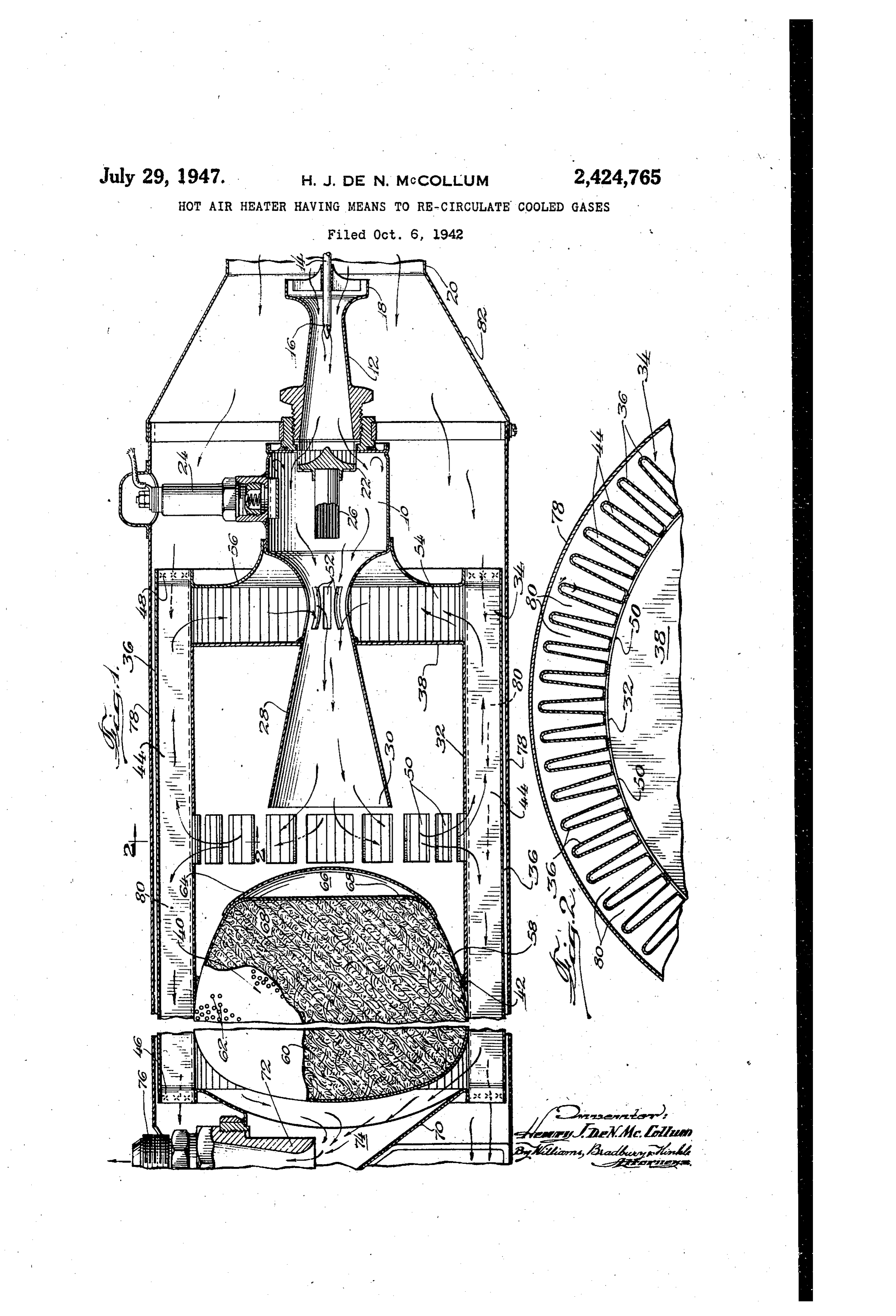
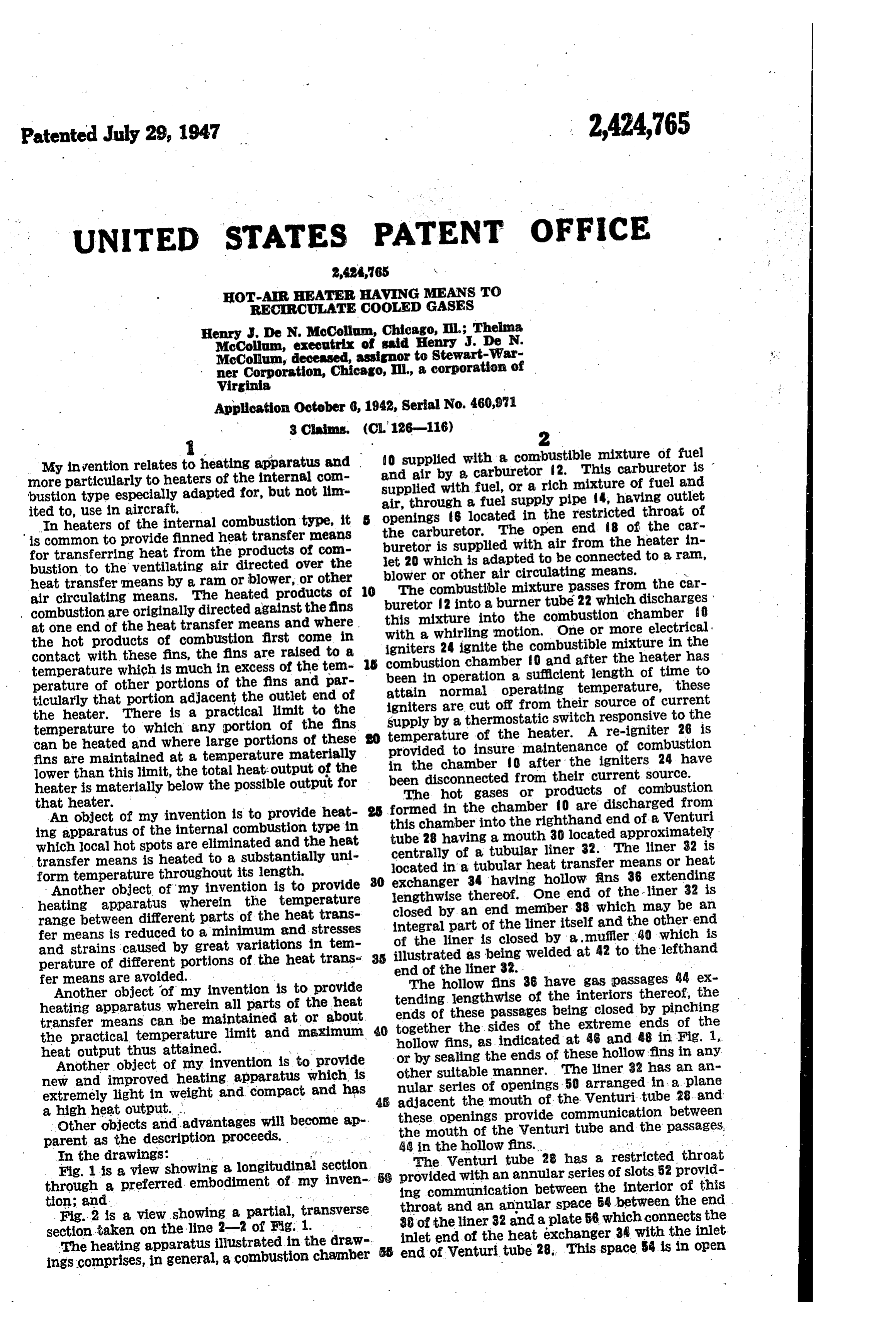
My invention relates to heating apparatus and and air by a carburetor 2. Thismixture ?o supplied with a combustible of fuel carburetor is more particularly to heaters of the internal com supplied with fuel, or a rich mixture of fuel and bustion type especially adapted for, but not lim air, through a fuel supply pipe 4, having outlet ited to, use in aircraft. openings 6 located in the restricted throat of In heaters of the internal combustion type, it is common to provide finned heat transfer means the carburetor. The open end 8 of the car buretor is supplied with air from the heater in for transferring heat from the products of com let 20 which is adapted to be connected to a ram, bustion to the ventilating air directed over the blower or other air circulating means. N heat transfer means by a ram or blower, or other 10 The combustible mixture passes from the car air circulating means. The heated products of buretor 2 into a burner tube 22 which discharges combustion are originally directed against the fins this mixture into the combustion chamber 8 at One end of the heat transfer means and where with a whirling motion. One or more electrical the hot products of combustion first come in
Contact with these fins, the fins are raised to a 3 igniters 24 ignite the combustible mixture in the combustion chamber O and after the heater has temperature which is much in excess of the tem been in operation a sufficient length of time to perature of other portions of the fins and par attain normal operating temperature, these ticularly that portion adjacent the outlet end of igniters are cut off from their source of current the heater. There is a practical limit to the supply by a thermostatic switch responsive to the temperature to which any portion of the fins temperature of the heater. A re-igniter 26 is can be heated and where large portions of these provided to insure maintenance of combustion fins are maintained at a temperature materially in the chamber 10 after the igniters 24 have lower than this limit, the total heat output of the been disconnected from their current Source. heater is materially below the possible output for . The hot gases or products of combustion that heater. formed in the chamber f0 are discharged from An object of my invention is to provide heat this chamber into the righthand end of a Wenturi ing apparatus of the internal combustion type in tube 28 having a mouth 30 located approximately which local hot spots are eliminated and the heat centrally of a tubular liner 32. The liner 32 is transfer means is heated to a substantially uni located in a tubular heat transfer means or heat form temperature throughout its length.
Another object of my invention is to provide 80 exchanger 34 having hollow fins 36 extending heating apparatus wherein the temperature closed by anthereof.
lengthwise end
One end of the liner 32 is member 38 which may be an range between different parts of the heat trans integral part of the liner itself and the other-end fer means is reduced to a minimum and stresses of the liner is closed by a muffler, 0 which is and strains caused by great variations in ten illustrated as being welded at 42 to the lefthand perature of different portions of the heat trans 35 fer means are avoided. . end of the liner 32.
Another object of my invention is to provide tendingThe hollow fins 36 have gas passages 44 ex lengthwise of the interiors thereof, the heating apparatus wherein all parts of the heat ends of these passages being closed by pinching transfer means can be maintained at or about 40 together the sides of the extreme ends of the the practical temperature limit and maximum hollow fins, as indicated at 46 and 48 in Fig. , heat output thus attained. : v or by sealing the ends of these hollow fins in any Another object of my invention is to provide other new and improved heating apparatus which is nular suitable manner. The liner 32 has an an series of openings 50 arranged in a plane extremely light in weight and compact and has 4. adjacent the mouth of the Wenturi tube 28, and a high heat output. . these openings provide communication between Other objects and advantages will become ap the mouth of the Wenturi tube and the passages, parent as the description proceeds. 48 in the hollow fins. . .. . .. . . -
Fig.the1 isdrawings:
a view showing a longitudinal section The Venturi tube 28 has a restricted throat through a preferred embodiment of my inven provided with an annular series of slots 52 provid ing communication between the interior of this tion;
2 is a view showing a partial, transverse throat and an annular space 54 between the end section taken on the line 2-2 of Fig. 1. 38 of the liner 32 and a plate 56 which connects the inlet end of the heat exchanger 34 with the inlet
The heating apparatus illustrated in the draw ess end ings comprises, in general, a combustion chamber of Venturi tube 28. This space 54 is in open
Page 3
, Communication with the righthand ends of the passages 44 in the hollow fins. combustion chamber 0. The gases flowing from The muffler 40 comprises a sheet metal shell the Space 54 into the Venturi tube 28 have given 58 containing a quantity of sound absorbing ma up most of their heat to the righthand end por terial 60, such as glass wool or stainless steel wool. tion of the heat exchanger 34 and are much cooler Openings 62 in the muffler shell form acoustic than the hot products of combustion leaving the couplings between the interior of this shell and combustion chamber 0. The intermixing of the interior of the liner 32 and also between the the cooled products of combustion from the space interior of the muffler shell and the passages 44 54 with the hot products of combustion from the the hollow fins. A rounded metal cap 64 is at 10 -combustion chamber materially cools the latter and reduces the temperature of the gases flowing tached to the righth and end of the muffler shell and cooperates therewith to form a combination through low fins.
openings 50 into the passages in the hol
heat insulating and resonance chamber 66, which With a proper proportioning of the parts, that is acoustically, coupled to the interior of the muf fier shell by opening 68. portion of the hot gases which is flowing to the 5 right in the hollow fins will heat the righthand
The lefthand end of the tubular heat exchanger 34 is closed by a plate 7 carrying an outlet fit ends of these fins to the same temperature as ting 2. An outlet chamber 74 is formed between the main portions of these fins are heated by the the plate T0 and the lefthand end of the muffler gases flowing to the outlet chamber 74. Further 40 and receives the cooled gases flowing there more, the cooling of the hot products of combus tion which into from the lefthand ends of the passages 44 in 20 with is effected by mixing these products the cooled recirculating. products of com the hollow fins. These gases are discharged to atmosphere through the outlet fitting 72 and any spots buistion avoids the formation of intensely hot suitable. exhaust pipe attached to the threaded ings in the heat exchanger adjacent the open end 76 of this fitting. 50. These advantages are effected with a minimum of additional structure and without the
A tubular casing 78 of sheet metal, or other 25 necessity suitable material, encloses the heat exchanger 34 of providing moving parts for creating and cooperates therewith to form ventilating air the recirculation of the products of combustion. passages 80 between the hollow fins 36. The Such additional parts as are necessary may be righthand end of the casing 8 is connected to a 30 made of lightweight material and do not substan conical extension 82 of the inlet 20 and receives tially increase the weight or size of the heating apparatus.
ventilating air therefrom. The lefthand end of the casing 78 may discharge directly into an air theSince my invention eliminates hot spots from heat exchanger, the entire area of this heat craft cabin or other space to be heated, or into a system of ducts for conducting the heated venti 35 exchanger may be operated at substantially the practical temperature limit for the particular lating air to Selected locations. material of which it is made. In practice the In the operation of my novel heating apparatus, the carburetor 2 supplies a combustible mixture walls of the heater are made as thin as is possi to the combustion chamber 0 and this mixture ble consistent with a reasonable margin of safety with respect to the ability of the walls to resist is fired by the electrical igniters 24. The hot gases 40 burning of combustion flow from the lefthand end of the out, My improved construction which combustion chamber O into the Venturi tube 28 causes a substantially more even application of and are discharged from the mouth thereof into the heat to the walls of the heater so as to avoid the development of hot spots is accordingly very the liner 32. These gases then pass through the important. My novel heating apparatus thus pro openings 50 in this liner into the passages 44 in wides the maximum heat output for a given size the interiors of the hollow fins at points spaced 45 and makes possible the provision of a compact some distance from the righthand ends of these passages. Part of these gases flow to the left Output.and lightweight heater having a maximum heat and give up their heat to the heat exchanger 34.
This part of the gases then enters the outlet While I have illustrated and described only a chamber 4 and is discharged to atmosphere 50 single embodiment of my invention, it is to be through fittings 72 and the exhaust pipe con understood that my invention is not limited to nected thereto. the particular details shown and described but , The remainder of the gases entering the inte Inay aSSune numerous other forms and that my riors of the hollow fins through openings 50 flow 55 invention is to be construed as including all to the right in the passages 44 where they give modifications and variations falling within the up the major portion of their heat to the corru Scope of the appended claims.
I claim:
gated wall by which the fins 36 are provided.
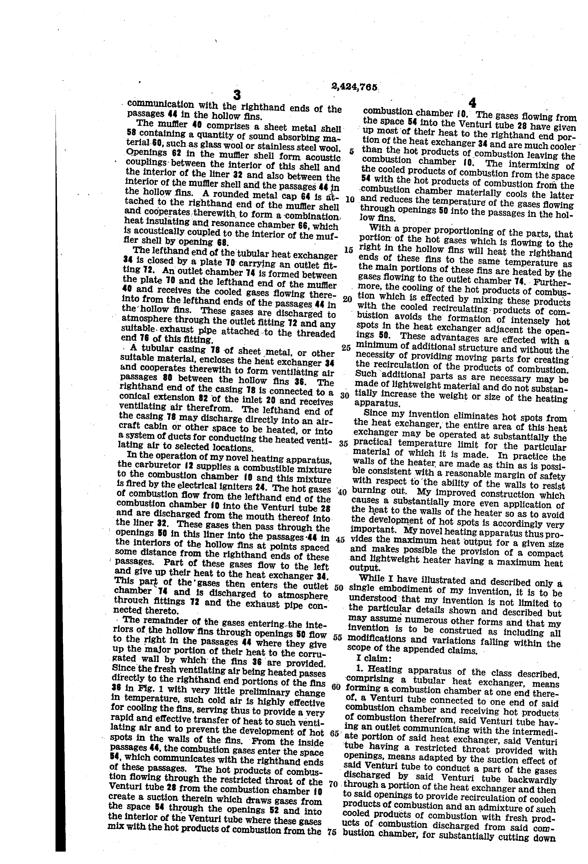
Since the fresh ventilating air being heated passes 1. Heating apparatus of the class described, directly to the righthand end portions of the fins 60 'comprising a tubular heat exchanger, means 36 in Fig. 1 with very little preliminary change forming a combustion chamber at one end there in temperature, such cold air is highly effective of, a Wenturi tube connected to one end of said for cooling the fins, serving thus to provide a very combustion chamber and receiving hot products rapid and effective transfer of heat to such venti of combustion therefrom, said Wenturi tube hav lating air and to prevent the development of hot 65. ing an outlet communicating with the intermedi . . spots in the walls of the fins. From the inside . ate portion of said heat exchanger, said Wenturi passages 44, the combustion gases enter the space tube having a restricted throat provided with 54, which communicates with the righthand ends openings, means adapted by the suction effect of of these passages. The hot products of combus said Venturi tube to conduct a part of the gases tion flowing through the restricted throat of the 70 discharged by said Venturi tube backwardly Venturi tube 28 from the combustion chamber fo through a portion of the heat exchanger and then create a suction therein which draws gases from to said openings to provide recirculation of cooled the space 54 through the openings 52 and into cooled products of combustion and an admixture of such the interior of the Wenturi tube where these gases products of combustion with fresh prod mix with the hot products of combustion from the 75 lucts of COmbustion discharged from Said com bustion chamber, for Substantially cutting down
Page 4
S bustion into the inside passages between the cor the temperature of said products of combustion rugations at an intermediate point along the heat prior to contact with the heat exchanger, and transfer member, means for feeding cold ventilat means for directing ventilating air forwardly in ing air forwardly into one end of said casing for close contact first with the portion of the heat movement through said outside passages, liner exchanger through which the gas flows back means for said heat transfer member in engage wardly and then with the remaining portion for ment with the inner edges of said corrugations heating the air and protecting the heat exchanger at the portions adjacent to the position at which from burning apparatus
Out. the hot products of combustion are delivered 2. Heating of the class described, thereto for causing such products of combustion comprising a tubular heat exchanger having hol to flow through said inside passages between the low fins extending lengthwise thereof, a muffler corrugations and serving to assist in the absorp located in one end of said heat exchanger, a tion of the heat at said intermediate point, and liner located in the other end of Said heat ex means at the end portion of said heat transfer changer, said liner having a closed end and an 5 member adjacent to the position at which said open end connected to said muffler, said liner be ventilating air is delivered into said casing adapt ing provided with gas ports intermediate its ends, ed by a suction effect to draw a portion of said means forming a combustion chamber for sup hot products of combustion backwardly along the rear end portions of said inside passages for de plying hot gases to the interior of said liner, said hollow fins providing gas passages communicat 20 livery with the fresh products of combustion. ing with the interior of said liner through said HENRY J. DE N. McCOLLUM. ports, and a Venturi tube interposed between said liner and combustion chamber, said Wenturi tube REFERENCES (CTE) , having a restricted throat communicating with one end of said hollow fins and functioning to The following references are of record in the create a recirculation of gases and mixture of 25 file of this patent:
these recirculated gases with gases leaving said combustion chamber. UNITED STATES PATENTs 3. In a heating apparatus of the class described, Number Name . Date the combination of a heat transfer member 1,737,681 Plassman ----------- Dec. 3, 1929 formed of sheet metal provided with deep, long 30 1,671,448 Plassman ----------- May 29, 1928 tudinal corrugations from end to end thereof, a 1,614,359 Gaston ------------- Jan. 11, 1927 casing Surrounding said member so as to provide 1,633,549 Little -------------- June 21, 1927 outside passages for air along the full length of 1,790,870 Mantle et al. --------- Feb. 3, 1931 said member between the corrugations and the 2,224,544. Keller -------------- Dec. 10, 1940 casing, means for feeding hot products of com- sis
Provenance
- Collection
- Cited prior art
- Original PDF
- patentimages.storage.googleapis.com →
- Filed
- 1942-10-06
- Pages
- 4
- Method
- pdftotext (the PDF's own text layer) + pdftoppm 300dpi page scans
- Source
- Google Patents bibliographic record
- Granted
- 1947-07-29
- Inventors
- Mccollum Thelma; Stewart Warner Corp
- Transcribed from
- patentimages.storage.googleapis.com →