patent · US1684079
Liquid-fuel burner and control mechanism therefor
11 September 1928
Page 1
Drawing sheet — no readable text.
Page 2
Drawing sheet — no readable text.
Page 3
Patented Sept. 11, 1928. 1,684,079
UNITED STATES PATENT OFFICE.
RAYMoRD E. WHITE, OF CHICAGO, ILLINOIs, ASSIGNOR. To TUBAL BoLLER com
A CORPORATION OF LILNOIS.
PANY, OF CHICAGO, ILLINOIS,
LIQUID-FUEL BURNER AND CONTROL MECHANISM THEREFOR.
Application filed December 14, 1921. Serial No. 522,350.
The present invention relates to a liquid signed. If this speed is reduced materially. fuel burner and control mechanism therefor. their efficiency drops off at a much higher rate, with the result that an unreliable con
The present burner has been developed with trol of the air blast is obtained, and with a the ultimate object of supplying a reliable 60 5 and efficient liquid fuel burner for the boilers considerable loss of power.
of self-propelled vehicles, such as steam auto difficulties,With the view to overcoming the above mobiles, trucks, tractors, etc. It will be CE it is one of the principal objects
parent, however, as the description proceeds, two separate blasts,invention to divide the air supply into that the burner has a much wider field of one a primary or atomiz 65 O utility, having particular application where ing blast for atomizing the fuel, and the other nicety of control under varying boiler loads athesupplementary blast which cooperates with primary or atomizing blast of air for con is desirable. It will further be apparent that trolling certain of the important features of the in atomizingtheblast rate of firing. The primary or of air is always maintained, 70 vention are not strictly confined to liquid 5 fuel burners, and accordingly the appended during the operation of the burner, at a rela claims have been drawn to cover these fea tively high velocity in order to effectively tures as employed in connection with burn incidentsthe atomize
fuel fed thereto. It is one of the the control of the burner to regu ers generally for different kinds of fuel, of late the quantity which pulverized coal is a typical example. through a relativelyof wide liquid fuel supplied 75 range, but the 20 The atomizing type of liquid fuel burner has such pronounced advantages over the velocity of this atomizing blast of air is suffi. cient to effectively atomize at all times all vaporizing type of burner for steam vehicle of practice that it is now becoming the preva airthe liquid fuel fed to it. The volume of supplied by this atomizing blast is pro ient type in this field. However, there are 25 certaininherent difficulties in the atomizing portioned to produce the proper volume of burner which have heretofore retarded its mixture for firing the boiler at a fraction of its maximum rate; in the present instance development, particularly where control is this an essential factor. One of these difficulties third,fraction is in the neighborhood of one is the necessity of maintaining at all times When which is, of course, merely exemplary. a higher rate of firing is desired, the 30 during the burner operation a blast of air of sufficient velocity and volume to properly supplementary increases the air blast comes into play and volume of mixture to any extent atomize the fuel. The difficulty becomes ap desired. It is also one of the objects of the parent when it is attempted to control, a burner by reducing the volume and velocity such invention to provide improved means for of the atomizing blast of air. If such air controlling the volume of liquid fuel fed to 90 blast is reduced to a point where there is not the feed burner in accordance with the selective of air to the burner from one or both of sufficient velocity to break up and atomize said air blasts.
the fuel the fuel enters the combustion cham Another particular object of the invention 95 ber in large globules or in unbroken liquid is to provide means which will control the form, with the consequent production of a volume of air supplied to the burner without smoky fire, the deposition of soot on the substantially varying the boiler tubes, and like difficulties resulting blast creating mechanism. speed The of the air power for from the burning of an improperly composed creating these air blasts may be derived from 100 mixture. If the air conduit or nozzle is made an electric motor, a steam rotor, sufficiently small so that adequate velocity is as a result of the present control system, may etc., which, maintained at the lowest rate of firing the be run continuously at its most efficient speed nozzle or conduit chokes the air supply when during all periods of the burner operation. an increased volume of air is supplied for a The control system for the present burner higher rate of firing.
Another difficulty in the atomizing burner preferably embodies means for shutting off 05 results from the attempt to control the air the operation of such power device entirely when the boiler pressure becomes excessive, blast by controlling the speed of the blower so that the control of such power device is or - ther blast creating means. In the major preferably secured by intermittent operation C ity of instances these blowers are only at a definite speed for which they are de efficient rather than by speed variation.
Page 4
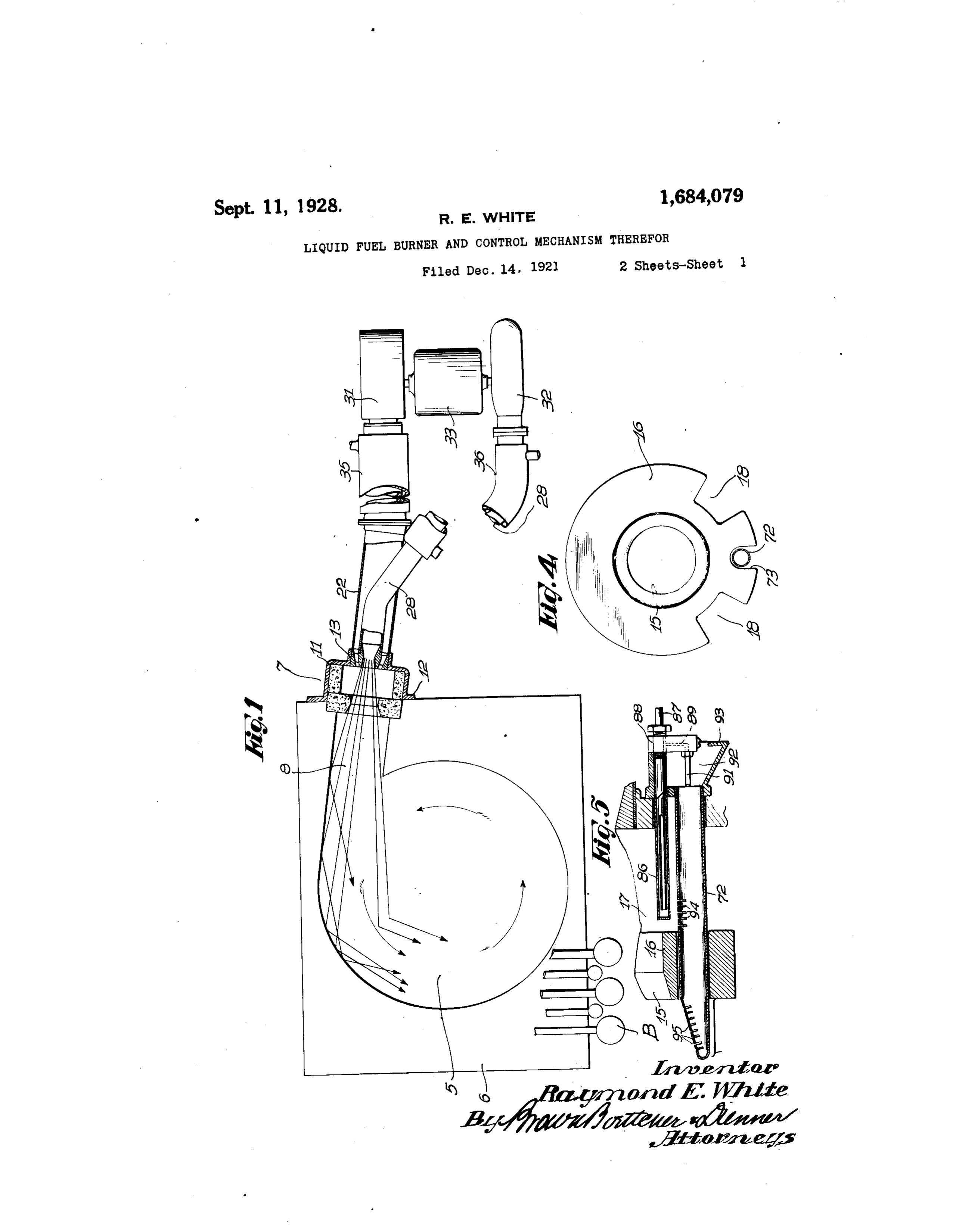
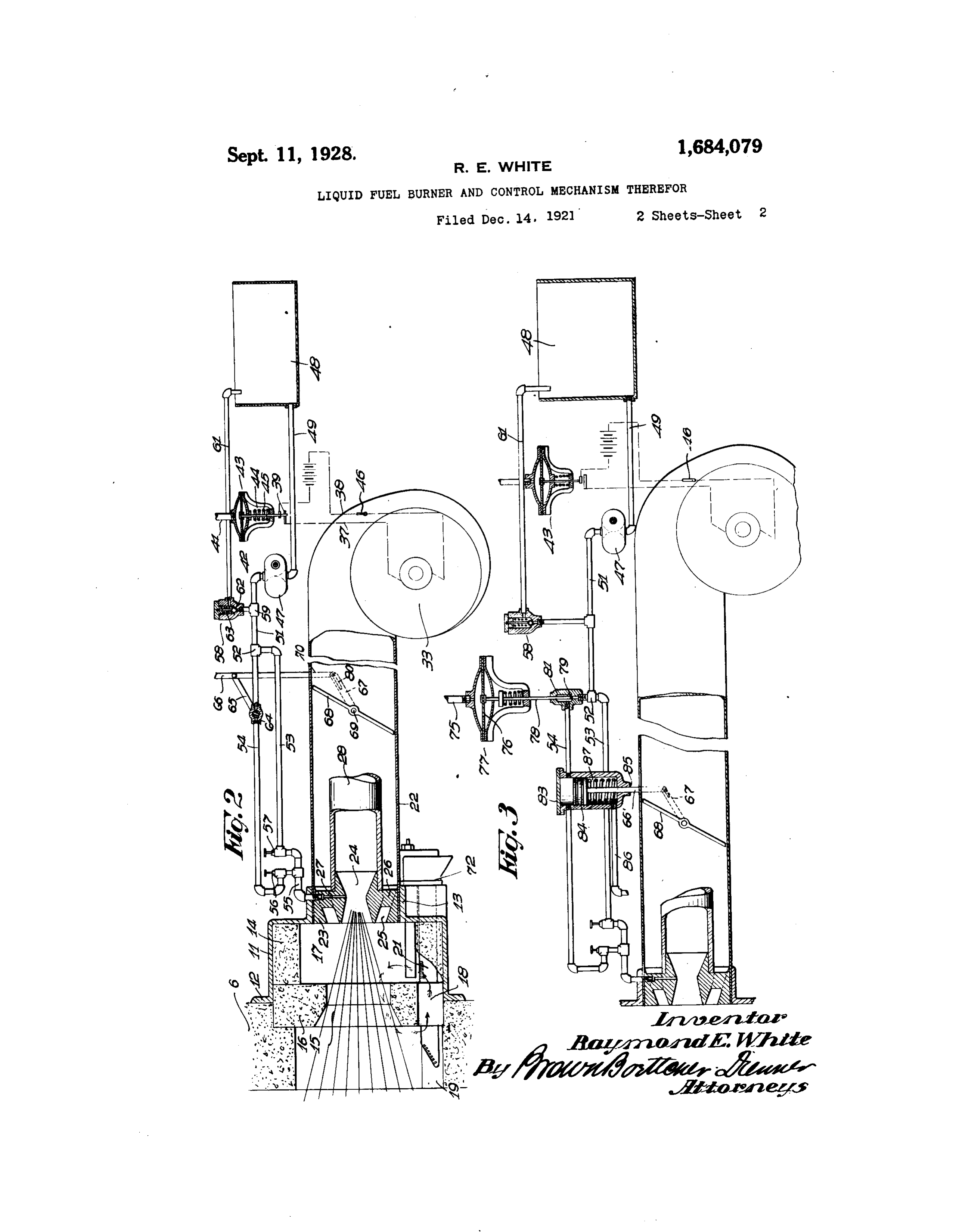
Viewed in another aspect, the invention culating openings 18 are provided in the low may be considered as embodying two burners er circumference of the diaphragm 16, and or two mixture producing devices, one of . these openings align with grooves 19 in the which is operable alone to maintain a certain refractory setting and with angular passages relatively low rate of firing, and the other of 21 in the insulating ring 14. The relative O which is operable conjointly therewith for pressures prevailing on opposite sides of the increasing the rate of firing. diaphragm 16 induce a circulation through Referring now to the accompanying draw the openings 18 in the direction indicated, ings wherein I have illustrated a preferred whereby products of combustion flow into the O embodiment of my invention for the purpose regenerative chamber 17 and enter the mix 5 of acquainting those skilled in the art how to ture stream, effectively vaporizing the whole construct and use the same: fuel chargetherein. The heat of the carbon Figure 1 is a plan view of the burner ap monoxide generated in this chamber 17 va paratus; porizes such fuel particles as are not com 15 Fig. 2 is a fragmentary side view, partly pletely atomized and secures the vaporiza in section, and illustrating the control mech tion of the entire fuel charge. anism diagrammatically; Mounted in the hub or flange 13 is an air Fig. 3 is a view similar to Fig. 2 illus conduit 22 which supplies the supplementary trating a completely automatic control sys blast of air to the burner. A compound noz 20 ten ; zle in the form of a single casting 23 is mount Figure 4 is an elevational view of the re ed within the end of the conduit 22, this noz fractory diaphragm; and zle comprising an inner Venturi tube 24 and Eigure 5 is a sectional view of the pilot. an outer nozzle passageway 25. The inner Referring to Figure 1, the combustion Venturi tube 24 is supported in the outer 25 chamber or fire box 5 is defined in a refrac tube by spider arms 26, and extending tory setting 6 which is disposed under the through one of these spider arms is a fuel boiler B, according to any conventional prac feeding passageway 27 which discharges sub tice. The burner is designated 7 in its en stantially at the throat of the Venturi tube 24. tirety, and is disposed close to one side of The atomizing blast of air is fed to the inner 3) the setting for a tangential discharge venturi 24 through a conduit 28 which fits 95 through the passageway 8 into the circular Over the projecting end of the inner Wenturi combustion chamber 5. This tangential in tube and which enters the supplementary air jection of a high velocity mixture into a cir conduit 22 diagonally, as shown in Figure 1. cular combustion chamber produces a rotat The air conduit 22 leads to the outlet of a 35 ing flame path which rises helically up be blower 31, and the air conduit 28 extends to 00 ...tween the tubes of the boiler. By thus re the discharge outlet of a separate blower 32. volving the products of combustion and heli The two blowers are mounted at opposite ends cally wrapping the flame upon itself, a maxi of a power unit 33, which may be a steam mum extent of flame space and a maximum rotor, an electric motor, or other suitable 4) combustion interval can be obtained from a power means. In the preferred embodiment very confined combustion area. The advan shown, this power unit is illustrated as being tages of this are well known; the long flame an electric motor owing to its greater facility space and the extended combustion interval of control, this motor being operated from a insuring complete combustion of the mixture storage battery carried in the vehicle. As before the same strikes the relatively cold illustrative of a typical relation of blowers, O tubes of the boiler. an installation which has operated satisfac The burner 7 is housed in a circular cas torily employed a blower 31 of proper design ing 11 having a flange 12 which is secured to for creating an air blast of substantially one the outside of the setting 6. A hub or flange ounce pressure or a velocity of approximately 50 13 supports the nozzle from which the mix 50 feet per second, and a blower 32 was em 5 ture is discharged. For protecting the hous ployed which would produce a blast of sub ing 11 the interior thereof is lined with a ring stantially four ounces pressure or a velocity 14 of heat refractory material. The mixture of approximately 100 feet per second. It is is directed through a generally tapering noteworthy that the above pressure of the 55 opening 15 in a heat refractory diaphragm atomizing blast is relatively low as compared 20 16 which is set in a recess in the refractory with pressures which have heretofore been setting 6. The area anterior or to the front necessary for the complete vaporization of of the diaphragm 16 constitutes a regenera the fuel oil or kerosene. This is because in tive chamber 17 which has as its function to the majority of prior constructions the break complete the vaporization of the whole fuel ing up of the fuel was performed entirely 25 charge. The parts are preferably so pro mechanically by the high velocity of the air portioned that the velocity of the mixture blast. In the present embodiment the final discharged through this chamber and gasification of the fuel is performed partly through the opening 15 tends to create a mechanically and partly by heat. The ap slight vacuum in the chamber 17. Re-cir plication of heat occurs in the regenerative 30
Page 5
chamber 17 where a quantity of incompletely or regulated with the primary and supple burned mixture is circulated up into the en designed blasts mentary of air. The fuel pump 47 is tering mixture stream and by its relatively or slightlytoindeliver excess fuel at a rate equal to of the maximum require high temperature completes the vaporization ments of the burner, and when the fuel dis of these fuel particles which have not been charge is restricted a suitable broken up by atomization. For E. (O- excess fuel discharged from therelief for the bustion this final vaporization should occur necessary. This is provided in thepump 47 is before ignition of the mixture and such action relief valve 58 which has connection atof59a form as attained in the present construction. By in the supply pipe 51, and which has a return 5 O thus using heat to assist in the final gasifica tion of the fuel a lower velocity and pressure pipe 61 discharging the excessfuel back to of air in the atomizing blast suffices, and con the supply tank 48. A suitable ball valve 62 sequently less power is required for the oper held to its seat by an adjustable spring 63 performs the above relief function. Inter SO ation of the blowers. posed in the supplementary fuel supply pipe 5 It may be desirable to heat the two blasts of 54 is a suitable valve 64 which is manually air to a certain extent, and to this end the operable to shutoff the fuel flow through the supplementary air conduit 22 is provided pipe 54, and which may be designed to meter with an exhaust steam jacket 35, and the the fuel flow therethrough. The movable atomizing blast conduit 28 is provided with element of the valve has connection through 20 a similar jacket 36. The manner of circulat the operating arm 65 with ing the exhaust steam through these jackets 66 which extends up to an accessible point a link or rod will be obvious to one skilled in the art. The in the driver's compartment, such as heat thus imparted to the air blasts also assists able control member on the steering column to a suit in the vaporization of the fuel.
Referring now to the semi-automatic con or rod on the dash. The lower end of the control 66 has pivotal connection through a link trol system for this burner, it will be noted 70 with from Fig. 2 that the circuit for the motor 33, valve 68 the operating arm 67 of a throttle which is pivoted in the supplemen extending through the wires 37 and 38, is in tary air conduit 22 upon a transverse shaft 5 terrupted by a suitable switching unit 39, 69. The arm 67 is preferably slotted as indi which is preferably of a snap type for quick cated at 80 make and break. The position of this switch is adapted toandbethe lower end of the link 70 is controlled by boiler pressure acting desired point in adjustably clamped at any through the pipe line 41 upon a diaphragm of convenient adjustment of theThis the slot 80.
angular permits tim 42 of a pressure responsive element 43. This ing between the valves 64 and 68. diaphragm has operative connection with the Upon initiating the operation of the burner OO movable switch element through the rod 44, the mixture is ignited from a pilot light a spring 45 normally tending to raiseThis the which is supplied with fuel through the pilot diaphragm and close the switch 39.
pressure responsive device is set to operate at burner part of tube 72 entering through the lower the main burner housing 7. The pilot 40 the maximum pressure at which the boiler tube 72 extends beyond the diaphragm 16 is to operate, and upon attaining this pressure the device automatically cuts off the electric through a slot 73 in the lower periphery of motor 33 so that all further firing of the boiler the diaphragm. This pilot burner is illus is interrupted. A manual control switch 46 trated in detail in Figure 5 and comprises a 10 is preferably inserted in the circuit 37-38 vaporizing tube 86 which projects into the regenerative chamber 17 above the pilot to turn the system on or off.
The shaft 34 of the electric notor 33 is burner tube 72. The fuel which is normally extended beyond one of the blowers to have supplied to the main burner may be employed operative connection with a fuel pump 47. in this pilot burner, or a more volatile fuel 5 such as gasolene may be employed. The fuel 50 For simplicity, this fuel pump is preferably enters the vaporizing tube 86 through a sup a positive pressure gear pump having its ply tube 87 which enters the closed front end inlet supplied with fuel from the supply tank of 48 through the supply pipe 49. The outlet centthethevaporizing tube and discharges adja pipe 51 communicates through a T connec vaporizing tube 86 isend closed rear of said tube. The 2) highly heated and the 55 tion 52 with a primary fuel supply pipe 53 liquid fuel flashes into vapor in flowing back and a supplementary fuel supply pipe 54.
These two supply pipes again merge into a along which the bottom of the tube to the outlet is located at the closed front end of common pipe 55 which discharges into the the vaporizing tube. This outlet is through 25 fuel feeding passageway 27 opening into the a passage 89 extending down through a block. 60 inner Venturi tube 24. Anterior to their common point of connection with the pipe 55 88 mounted on the end of the vaporizing tube. the two supply pipes 53 and 54 are provided A nozzle 91 is carried on the block 88 and with separate regulating valves 56 and 57, by communicates with the passage 89 to dis-, which the respective rates of fuel discharge charge the heated fuel vapor into the open 30 66 through the pipes 53 and 54 may be balanced front end of the burner tube 72. The injec
Page 6
4 . 1,684,079 p
tion of this fuel vapor induces a flow of air which is necessary to be admitted for in through the Venturi mouth 92, which is pref creased rates of firing.
erably flanged at its lower edge as indicated In Fig. 3 I have shown a control system at 93 for forming a pocket for the accumu wherein the feeding and regulation of this lation of a limited volume of liquid fuel. The added increment of mixture is performed au burning of such accumulation of fuel in this tomatically in accordance with the demands pocket serves to heat the nozzle 91, block 88 of the boiler. In this system the automatic and vaporizing tube 86 for the purposes of control of the electric motor 33 is still re starting. The intermediate portion of the tained, so that the burner will be cut out of 0. burner tube 72 is provided with a plurality operation entirely when the boiler pressure 75 of slots or holes 9-in its upper periphery in reaches a predetermined maximum. When position for heating the vaporizing tube 86. the boiler pressure reaches a predetermined The end of the burner tube beyond the dia point slightly below this maximum pressure, phragm 16 is provided with a diagonally ar at which point it is desirable to reduce the 5 ranged series of slots or holes 95 for igniting rate of firing, this boiler pressure acts through 80 the main mixture stream. It should be noted a pipe line 75 upon the diaphragm 76 of a that the heat rising from the flames emitted pressure responsive element 77. This dia from the slots 94, beneficially acts on the phragm, operating through a rod 78, controls main mixture stream passing through the re a valve 79 in a valve housing 81 interposed in 20 generative chamber 17 by assisting in the va the supplementary fuel supply pipe 54. The porizing action above described. rise and fall of the valve 79 in response to the The atomizing blast of air discharged flexure of the diaphragm 76 regulates the flow through the conduit 28 and the primary vol of fuel through the supplementary supply ume of fuel discharged through the pipe 53 pipe 54 in an obvious manner. For the pur 90 25 combine to produce a certain volume of mix pose of automatically opening the throttle ture of a predetermined proportion for com valve 68 in accordance with the quantity of bustion when the boiler load is comparatively fuel flowing through the supplementary fuel light. This mixture may be of just sufficient supply pipe 54, a cylinder 83 is interposed in volume to meet the demands of the boiler this supply pipe. A piston 84 is adapted for 30 when operating at light loads analogously to reciprocation in this cylinder and has connec 95 an "idling” mixture in the case of an internal tion with the control rod 66 which extends combustion engine; or this mixture may be of upwardly from the throttle arm 67 and enters sufficient volume to supply all the ordinary the closed lower end of the cylinder 83 demands of the engine. This is a matter of through a boss 85. Any leakage of fuel past 00 35 design determinable only by the requirements the piston 84 is conducted by way of a pipe 86 of the particular installation. In either to the fire box, so that the cylinder will not event, when a greater volume of mixture is become clogged by the trapping of fuel below desired for meeting ordinary or overload de the piston and so that no loss of fuel can occur. mands on the boiler, the control rod 66 is de A compression spring 87 in the lower closed 40 pressed and the supplementary volumes of air end of the cylinder 83 normally tends to raise 05 and fuel admitted through the respective con the piston 84 and close the throttle valve 68. duits 22 and 54. This immediately increases In the operation of this ar. ment, the the volume of mixture to the desired extent, lowering of the boiler pressure will allow the the proportion of this increased volume of valve 79 to be raised, thereby initiating a flow O mixture being determined by the relative set of fuel through the supplementary fuel pi tings of the valves 56 and 57 and of connec 54, or increasing the rate of a flow gy tion between the link 70 and arm 67. It will existing in this pipe. This fuel will dis be apparent that by raising or lowering the charge into the Venturi throat, as in the pre control rod 66 this added increment of mix vious embodiment and will through the ture may be decreased or increased as desired. medium of the piston 84, open the throttle 5 Referring to the arrangement of the nozzles valve 68 to permit or increase the flow of sup or tubes 24 and 25 it will be seen that this plementary air through the conduit 22. The supplementary volume of air is directed by extent of opening of the throttle valve 68 the nozzle 25 angularly into the blast of mix will be determined by the rate of flow through 20 55 ture from the inner Wenturi tube. This en the pipe 54, which will exert a greater or hances the breaking up of the fuel particles less pressure on the piston,84. The pressure and insures an intimate commingling of the responsive element 77 which controls the two blasts. It will also be noted that the two admission of this added increment of mix tubes or nozzles exert a mutual aspirating ef ture is preferably set to operate between a 25 fect on each other. By thus supplying this range of pressures slightly below that at supplementary volume of air to the burner which the pressure responsive element 43 is through a separate conduit a sufficiently high set. For example, in a typical high pressure velocity is maintained in the inner venturi to installation, the pressure responsive element 77 could be set to operate at between 400 and 30 atomize the fuel atlow rates of firing without 425 65 choking the supplementary volume of air pounds and the pressure responsive ele
Page 7
ment 43 could be set to operate at between of firing, a Secondary air passageway for Sup 425 and 450 pounds. Thus, if the boiler pres plementing the volume of air during an ad sire tends to fall below the minimum setting vanced rate of firing, blower mechanism con tie valve 9 will initiate or increase the flow nected to said passageways, a throttle con. s of supplementary air for the purpose of trolling said secondary air passageway, a lringing the boiler pressure back to its pre fuel valve for increasing the supply of liquid determined range, and if the pressure tends fuel to said mixing chamber, means for si to exceed the maximum setting the Opera multaneously operating said fuel valve and 55 tion of the pressure responsive element 43 Said throttle, and igniting means located sub will interrupt the running of the motor 33. stantially posterior to the point of admixture in between these two limits the pressure re between said liquid fuel and said supplemen sponsive element may be made to maintain tary air supply.
a substantially constant pressure under all 3. In combination, a burner, fuel feeding 60 (rdinary conditions by regulating the volume means, a first air conduit connected to said of fuel discharged through the pipe 54. burne', a blower supplying a substantially Although I have described my invention constant volume of air to said first air con witi reference to a particular embodiment cluit, a second air conduit connected to said as required by the statutes, I do not intend burner, a blower for supplying air thereto, thereby to limit the invention to any of the means for controlling the discharge of air 20 (letails herein (described, as it is evident that through said second air conduit, and valve namerous modifications will at once be ap means co-operating with said latter control parent to those skilled in the art, and I de ling means for controlling the discharge of sire that all such modifications shall be con fuel from said fuel feeding means. 70 sidered as counir within the scope of the 4. In combination, a burner, an atomizing present invention, air conduit discharging thereto, a supple claim: mentary air conduit discharging to said 1. In a liquid fuel burner, the combination burner, a valve interposed in one of said con of a mixing chamber, means fol' supplying duits, fuel feeding means discharging to Said liquid fuel thereto. a primary air passageway burner, a fuel passageway connected thereto, for supplying the requisite volume of air to a valve in said passageway, means for shunt said mixing chamber for Supporting com ing fuel to said fuel feeding means around hisjon during a relatively low stage of firing, s: it vale, and control mechanisms connected seconda iy air passage way fol' supplying a to both of said valves. 80 supplementary volume of air to said mixing 5. In combination, a burner, a boiler adapt 5 chamber during an advanced stage of firing, ed to be heated thereby, means for feeding a throttle controlling the air flow through fuel to said burner, primary and secondary said secondary air passageway, valve means air conduits discharging to said burner, for supplementing the supply of liquid fuel blower mechanism for supplying air to said 85 to said mixing chamber, and actuating means conduits, control means responsive to con - i. co-operating with said throttle and said valve ditions in said boiler for controlling the oper S. m ation of said blower mechanism, a valve in 2. In a liquid fuel burner, the combination said secondary air conduit, a fuel valve con 90 of a mixing chamber, means for supplying trolling the fuel supply, and control means liquid fuel thereto, a primary air passage for controlling said valves. way for supplying the requisite volume of air In witness whereof, I hereunto subscribe to said mixing chamber for supporting com my name this 26th day of November, 1921. plete combustion during a relatively low rate RAYMONDE. WHITE.
Provenance
- Collection
- Cited prior art
- Original PDF
- patentimages.storage.googleapis.com →
- Filed
- 1921-12-14
- Pages
- 7
- Method
- pdftotext (the PDF's own text layer) + pdftoppm 300dpi page scans
- Source
- Google Patents bibliographic record
- Granted
- 1928-09-11
- Inventors
- Raymond E White; TUBAL BOILER Co
- Transcribed from
- patentimages.storage.googleapis.com →