patent · US2532740
Fuel burner provided with combustion gas recirculating means
5 December 1950
Page 1
Drawing sheet — no readable text.
Page 2
Drawing sheet — no readable text.
Page 3
Patented Dec. 5, 1950 2,532,740
FUEL BURNER PROVIDED WITH COMBUS
TION GAS RECRCULATING MEANS
William H. Speer, Moosup, Conn.
Application February 10, 1948, Serial No. 7,370
This invention relates to heating apparatus
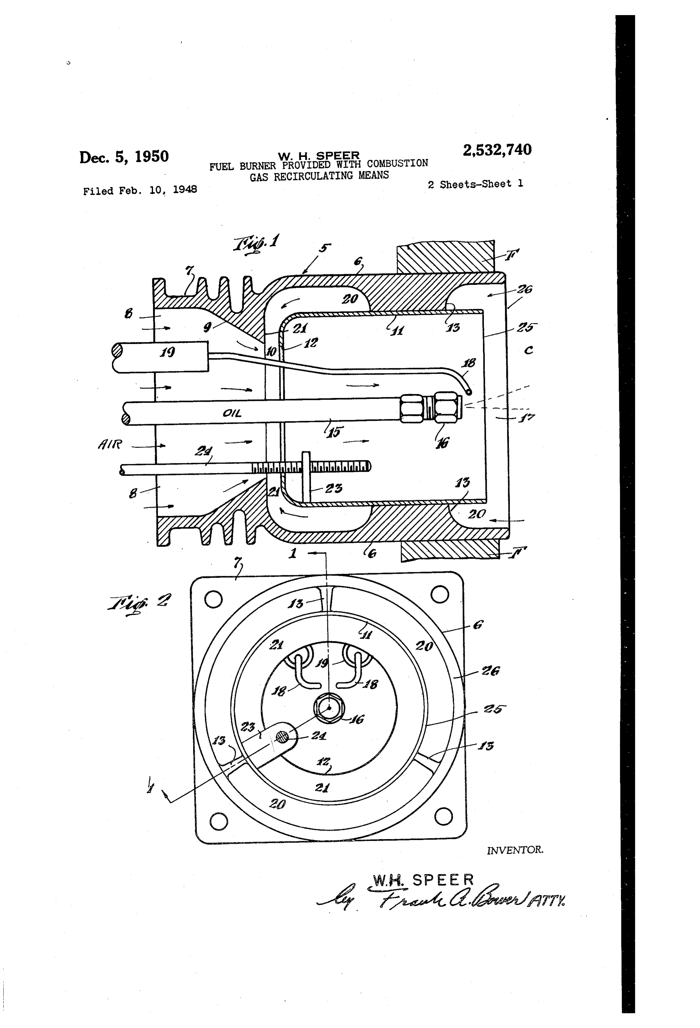
recirculation passages, 20. The liner if is ad and particularly to systems of combustion where justed longitudinally by sliding it in the re mechanical firing of oil, gas or other fuel re taining ribs 3 and rod 24 engages lug 23 to ceives air from a blower or other pressure Source provide for this adjustment from the outside to support combustion. This is a continuation of the apparatus. The front edge 25 of the liner in-part of my prior application Number 585,111, is positioned near the base of the jet and pref filed March 27, 1945, now abandoned. erably within the edge 26 of the burner head 5. The object of the invention is to provide for Preferably the nozzle 6 is of the atomizing the combustion of a fluid fuel by control of jet type giving a jet mist of very finely divided par and air supply formations and in particular O ticles. The air stream is ample in croSS Sec by combining with the main air supply a recircu tion with correspondingly moderate velocity com lation of gases from the combustion chamber and pletely Surrounding each atom of oil and holding the Supply of these gases to the flame by Syphonic the particles in suspension. This together with action in the air supply. the ignition gives control of the resulting flane Further objects of the invention particularly 5 and results in complete combustion within the in the construction of the combustion member high temperature of the flame generated gases to provide for this recirculation and admixtureWithin the high temperature refractory zone and of gases will appear from the following descripuntil combustion is completed.
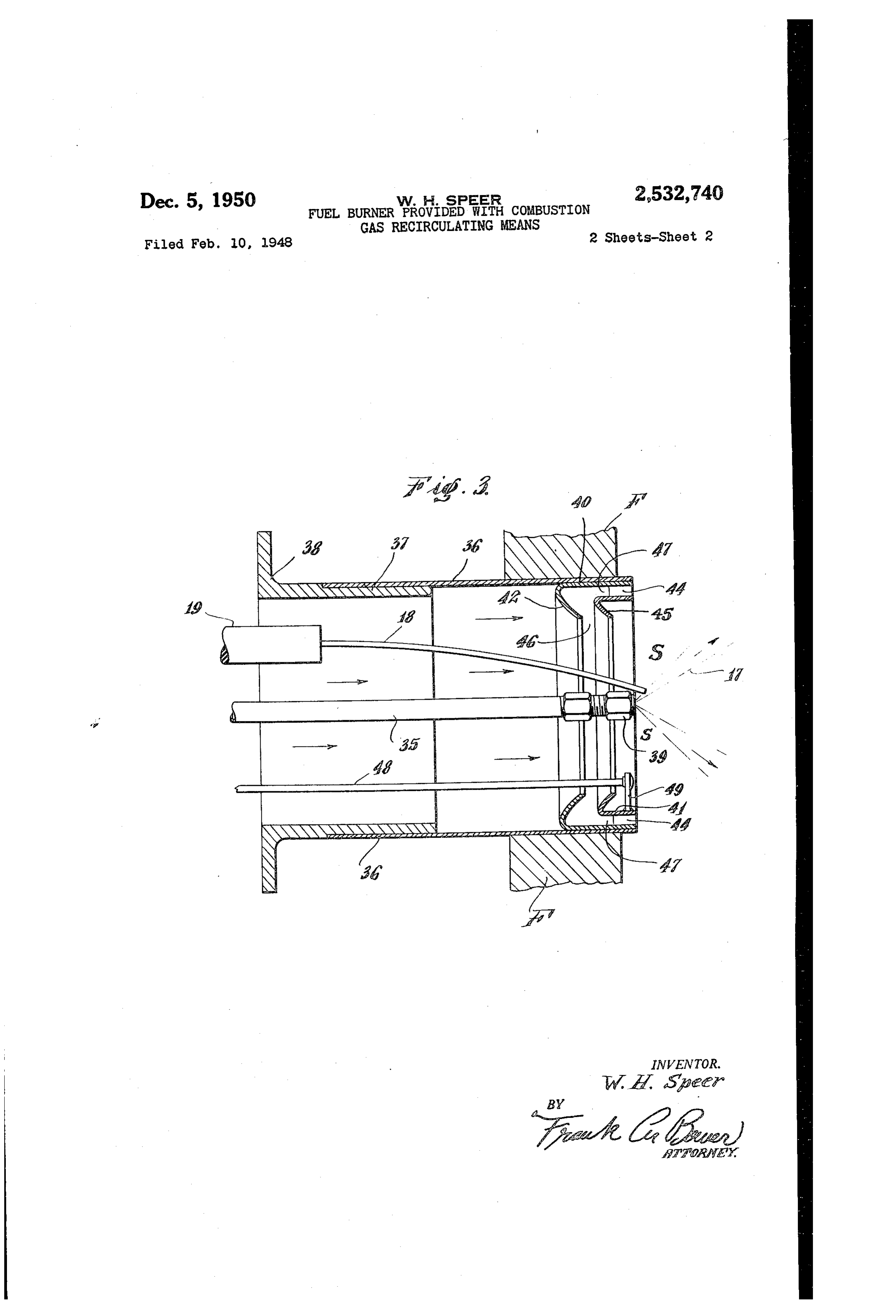
tion taken in connection with the following In the modification illustrated in Fig. 3 the drawings in which 20 body of the burner comprises a tubular member Fig. 1 is a sectional view taken on the line - 36 sleeved on the inner end 3 of an outer hous of Fig. 2 and showing a typical combustion head ing member 38, the oil pipe 35 being located at with a peripheral recirculation area around the the center and mounted to be longitudinally ad central burner parts; justable from outside the unit so as to position Fig. 2 is a front elevation of the apparatus the nozzle 39 at the inner end of the burner as shown in Fig. 1; and Shown or a few inches forward or back of this Fig. 3 is a view similar to Fig. 1 and illustrat position. The oil supply to this nozzle is under ing a modification. pressure, low or high, sufficient to atomize the In the specific embodiment illustrated, the oil being used into a Spreading jet having an burner head 5 is set in place in the furnace wall 30 angle of spread of about 60 or 80 or of about F and opens to the right into the combustion 50° to 100 where conditions make it preferable. chamber C. The burner head comprises an in The burner is thus of the 'gun' type producing ner cylindrical portion 6 and an outer ribbed a spray jet by pressure and burning this jet by a portion 7 of annular form providing the air in Supply of air to the jet as atomized and spread. let 8 leading to the contracting wall 9 concen 35 I have found it important to suspend or float trating the air stream and delivering it through this pressure formed jet in the combustion cham the opening O into the space within the head ber by surrounding gases and to this end the portion 6. fresh air supply is brought longitudinally around A liner member if f has an air inlet 2 posi the nozzle and is Supplemented by a recirculation tioned to receive the air entering from the open 40 of gases drawn from the combustion chamber ing 0, this liner being slidably supported co and preferably from the space S back of the axially within the head portion 6 by ribs 3. floating fame as in the forms illustrated in the The oil supply tube. 5 leads to the nozzle 6 drawings.
forming the spray jet under pressure, which In Fig. 3 this recirculation is provided by the jet is surrounded by the air stream from open 45 annular members 40, 4. The Outer member 40 ings O, 2. Ignition terminals 8 are provided is press fitted or otherwise fastened in place in supported from the insulators f9 at the outer the inner end of tube 36 as shown. So that the portion of the head. inturned end 42 of the insert will be at a slant The liner is surrounded by annular recircu across the path of the main air Supply. The
lation passages 20 leading toward the rear and inner member 4 is of less diameter and is slid into the space between the orifices f2 and fo ingly centered and supported in the cylindrical and around the periphery of the air stream pass end of member 40 by radial fins 44 carried either ing therethrough, so that the Venturi action of by the outer member 40 or the inner member this air stream lowers the pressure in the an 4 f. This inner member 4 f is provided with an nular neck 2 leading inward from the peripheral 55 inturned flange 45 matching the flange 42 of
Page 4
member 40 and having between them an inward viated by smoothing out of the airflow and a re directed passage 46 opening into the venturi duction of draft fluctuations affecting the flame. formed by the contraction of the air flow by the The resultant better controlled flame makes for conical fange 42. The suction of the flow cleaner fires and boiler passages. through the venturi draws gases inward from The hot gases being recirculated meet with passage 46 supplied from the annular entrance new air entering the combustion chamber between the members 40, 4 leading to the through the venturi 2, 46 thus raising the tem space s which intervenes between this passage perature of the mixture. The air consumption is and the base of the flame 7. The width of the made more complete and the volume of new air passage 46 may be varied by longitudinal adjust to be supplied is correspondingly reduced, avoid ment of the member 4t for instance by the rod ing excess air and improving the overal e 48 leading to adjusting means accessible from ciency.
outside of the burner and engaging the lug 49 The particular adjustment of the liner ,4 projecting upward from the member 4. The will depend upon the Venturi action desired and size of the intervening space S may be varied by 5 most efficient in each individual case. The wider longitudinal adjustment of the oil supply pipe the venturi 2 the further the orifice 2 will be 35 to shift nozzle 39 forward or back from the Spaced from the air jet Orifice to and the nar position shown. rower will be the air jet at the point of entry into This recirculation of gases from the Space S the orifice f2, so that the tendency will be to in around the jet f 7 uses these gases to decrease the 20 crease recirculation with widening of the Wen amount of fresh air supplied while at the same turi neck by inward movement of the liner. time maintaining an adequate volume of gas Normally the atomized fuel and the air mix mixture to float the fame as well as maintain the ture will float the flame a predetermined distance combustion. into the combustion chamber C and the recircu The result is a lowering of the exceSS air paSS 25 lated gases will be drawn in through the annular ing through the combustion chamber and an in area surrounding the base of the flame so that the crease in the percentage of carbon dioxide in the flame near the burner head is encased in counter fiue gases. In the apparatus as illustrated in currents of the combustion gases.
Fig. 3 the Venturi action is concentrated at or The burner head may be supplied as an ac just back of the base of the flame. 30 ceSSory or may be built into the equipment as Consequently the main air supply and the re originally installed. It is nonmechanical in op circulated gases combine with the jet all around eration. The fuel is burned at approximately in the space S as the jet is projected from the atmospheric pressure due to the relief of pres burner holding the fiame in suspension in the sure either directly in the combustion chamber high temperature combustion chamber to com 35 or from some remote point, for instance adjacent plete the burning of the oil. Contact of the the Smoke pipe. The mixture is accomplished by filame with surrounding surfaces of the burner is the Venturi action which produces a partial avoided altogether and there is ample separa vacuum at 20, 47 resulting in a mixture of the tion preventing any coking or accumulation of fresh and recirculated gases at 2, 46 (Figs. 2 and deposits on the metal parts. 40 3). The actual primary air for combustion is In the device shown the supply for the recir relatively reduced in amount due to the pick-up culation is drawn in through an annular area of gases from the combustion chamber or other surrounding the space S and thus includes a Source. The fame is thus supported by the re large part of the unconsumed air and gases circulated gases with a consequent saving in around the flame and not mixing therewith, AS the primary air and greater efficiency in the the recirculation being remixed with the main Overal burning of the fuel. air stream on its way to the fame. Increments It also provides for favorable expansion of the of the unconsumed air are thus carried around in flame in a heating boiler permitting it to be dis the recirculation circuit and the combustion is tributed and supplied most advantageously to the rendered more complete. The action automat 50 surfaces to be heated. The only draft needed is ically adjusts itself to the varying conditions in from the breach to the chimney in order to vent the furnace permitting a wide control of the the released products of combustion from the flame while attaining efficient conditions of com heat unit.
bustion. In the burner shown, the oil pressure line is at At the same time the recirculation of the ac SS relatively high pressure but the air supply and cessory gases from the combustion chamber and recirculation is equally applicable to burnersus its admixture with the incoming air aids in in ing a lower pressure oil supply in the neighbor suring efficient overall combustion and adds to hood of five pounds for instance or less. The the control of the combustion gases in the burner burner head of Figs. 1 and 2 is of simple forma and the combustion chamber. tion involving merely the tubular casting 6, 7. By withdrawing and recirculating the gases and the liner. with the rod 24 extending back from the combustion chamber, the pressure in ward for accessible manipulation at the outside the boiler is reduced. The draft requirements as of the burner. The burner head of Fig. 3 involves ordinarily figured are necessarily less and the in its structure a simple assembly of the recircu release of products of combustion through the lation rings 40, 4 at the inner end of the tubular boiler is slowed down with consequent permis member 36. These typical embodiments illus sible restriction of the boiler passages and greater trate the operation and advantages of this system eficiency in their heat absorption. of recirculation, but the invention is not limited The combustion itself is quieter due to the to the specific details shown. It is intended to muffling effect of the recirculation, and the 70 cover such modifications as fall within the scope creation of a Wenturi pressure area in the air of the appended claims, stream tends to equalize the fan impulses. Good claim:
firing adjustment is not dependent upon higher 1. A fuel burner adapted to project a flame into draft setting and a lower more normalized draft the combustion chamber of a furnace compris pull may be employed and thus fluttering is ob ing a forward member having an outer wall
Page 5
adapted to fit into the furnace wall and formed wardly open end and an air supply portion rear with a nozzle chamber and with a rear air sup wardly thereof, a liner slidingly mounted in said ply opening, a fuel nozzle at the forward portion head portion, a fuel supply means having a noz of Said chamber adapted to atomize a liquid fuel zle positioned in the forward portion of said supply and direct the atomized jet into the com head, a contraction of Said air Supply portion bustion chamber, a rear conduit providing a fresh forming a Wenturi passage directing the air flow air Supply flowing through said opening forward into Said head portion, said liner and head por into the rear air supply opening of said nozzle tion being spaced to form passages between thern chamber, an inward directed wall member around for Supplying gases to said Wenturi passage, and Said rear air Supply opening, and a liner spaced 10 means for relatively adjusting said liner and said from said outer wall surrounding said fuel noz casing to vary th:2 cross sectional areas of Said zle to provide a passage and having a rear wall passages and correspondingly vary the induction cooperating with said inward directed wall to or Venturi effect of the air flow into Said head form an inward directed passage opening into portion and the relative proportions of the fresh said air Supply at the rear of said nozzle cham air and auxiliary gases.
ber to feed auxiliary gases into said air supply WLLAM. H. SPEER, on the way to said nozzle, said passage leading REFERENCES CTED from the combustion chamber to said inward directed passage for withdrawing gases from said The following references are of record in the chamber and leading Said withdrawn gases into 20 file of this patent:
Said inward directed passage for blending with UNITED STATES PATENTS the Said air flow on its way to the nozzle. Number Nanne Date 2. A fuel burner as set forth in claim 1 in which the conduit for the fresh air is tapered to a con 269.720 Russmann --------- Dec. 26, 1882
traction forming a Venturi passage into whicn 2.5 1,614,359 Trapp -------------- Sept. 4, 1900. the inwardly directed passage opens at the rear Gaston ------------ Jan. 11, 1927 of the nozzle chamber. 1,658,462 Peterson ------------ Feb. 7, 1928 3. A fuel burner as set forth in claim 1 in which 2,110,209 Engels -------------- Mar. 8, 1938 the conduit for the fresh air is tapered to a con 2,200,278 Johnston ---------- May 14, 1940
traction forming a Venturi passage into which 30 2,224,544 Hopkins ------------ July 9, 1940 the inwardly directed passage opens radially at Keller ------------- Dec. 10, 1940 the rear of the nozzle chamber. 2,357,622 Wiser -------------- Sept. 5, 1944 4. A fuel burner adapted to project a flame FOREIGN PATENTS into a combustion chamber comprising an outer Number . Country Date casing providing a head portion having a for 35 371,056 Great Britain ------- Apr. 21, 1932
Provenance
- Collection
- Cited prior art
- Original PDF
- patentimages.storage.googleapis.com →
- Filed
- 1948-02-10
- Pages
- 5
- Method
- pdftotext (the PDF's own text layer) + pdftoppm 300dpi page scans
- Source
- Google Patents bibliographic record
- Granted
- 1950-12-05
- Inventors
- William H Speer
- Transcribed from
- patentimages.storage.googleapis.com →