patent · US2518364
Direct fired air heater
8 August 1950
Page 1
Drawing sheet — no readable text.
Page 2
Patented Aug. 8, 1950
UNITED STATES PATENT office
DIRECT FIRED AIR HEATER
Charles C. Owen, Toledo, Ohio, assignor to Sur face Combustion Corporation, Toledo, Ohio, a corporation of Ohio
Application October 19, 1946, Serial No. 704,444
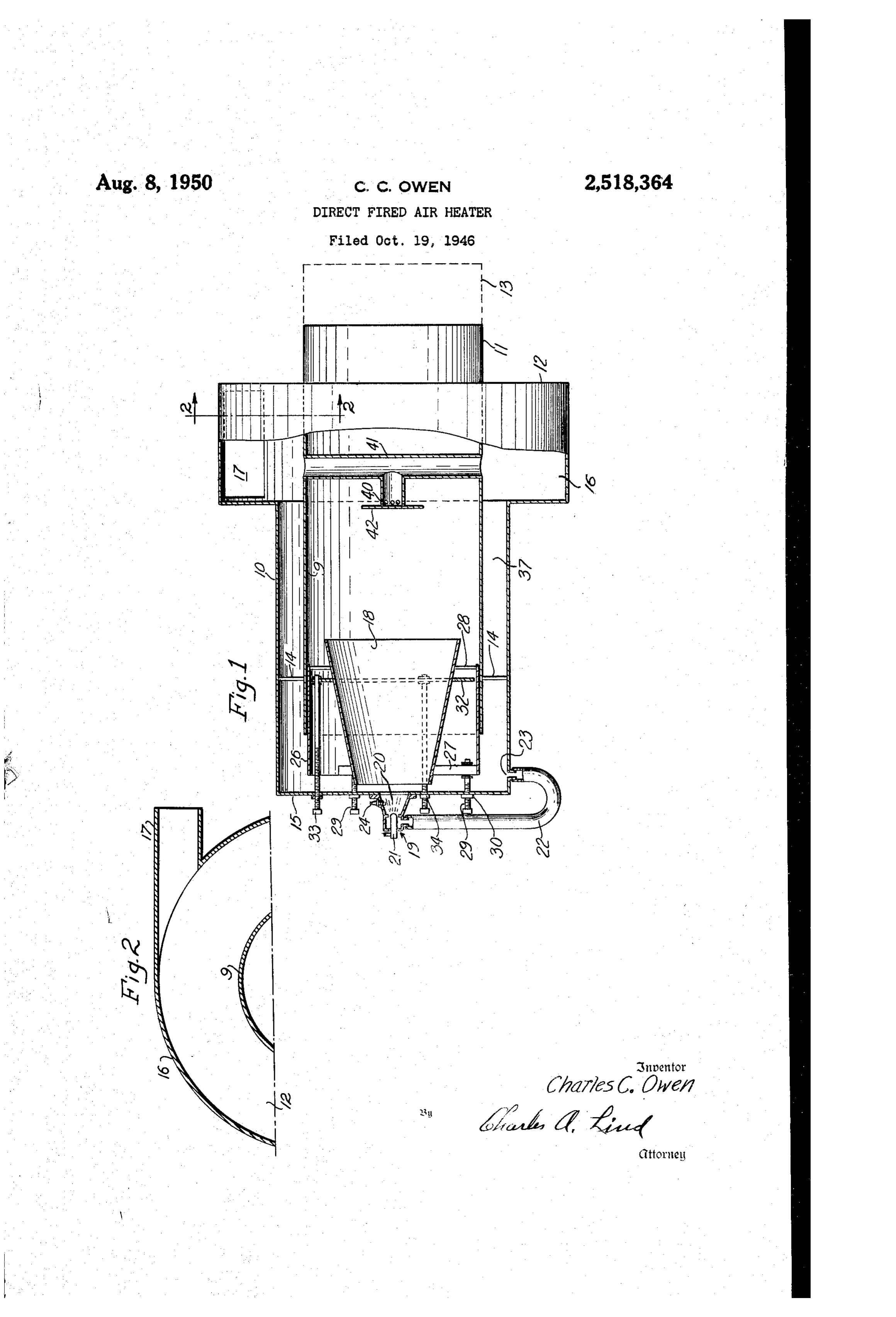
This invention relates to a portable combustion The front end wall of the air casing is indicated unit for use out-of-doors as in railroad yards at 5. A burner 9 is mounted on the outside and on highways for producing highly heated face of the wall if 5 coaxial with a central open gases for miscellaneous heating operations. The ing in the wall. The fuel will ordinarily be gaSo object of the invention is to provide a combus line because of its ready availability in the field tion unit which shall be well adapted for such but other fluid fuels may be used. In the case use and which shall be relatively simple in Con of liquid fuel, the preferred burner comprises struction. For a consideration of what I Con an atomizing nozzle 2 mounted at the Small end sider to be novel and my invention, attention is of a conical hood 20 which straddles the central directed to the following specification and the O opening in the wall 5, this hood also carrying claims appended thereto. a spark plug 24 for igniting the fuel. Partly to In the accompanying drawing forming part of help to keep the nozzle cool but primarily to this specification, Fig. 1 is a partial axial Section aerate the atomized fuel in the said hood for and side elevation of the improved combustion ready ignition, a stream of air from an air pipe unit without any showing of the supporting s 22 envelops the body of the nozzle and thence means, on which the unit will ordinarily be enters the conical hood 20 through an annular mounted such as a wheeled vehicle which will passage about the discharge end of the nozzle. also support the various adjuncts, such as, fuel The air pipe 22 connects with a small air outlet tank, power-operated blower, etc., for operating 23 in the air casing 0.
the unit. Fig. 2 is a fragmentary sectional view A metal shell 8 in the form of a truncated on line 2-2 of Fig. 1. cone is arranged coaxial With the combustion The improved combustion unit comprises a cylinder 9 with its large end within the latter combustion chamber defined by an open ended in radially spaced relation to provide an air pas metal cylinder 9 arranged with its front end sage therebetween for the entry of air into said within a cylindrical air casing ?o to receive air cylinder from the air casing 0 and with its Small therefrom. The discharge end of said cylinder end facing the burner 9 but axially spaced from is indicated at if and extends substantially air the wall 5 of the air casing to provide an air gap tight through the adjacent end wall. 2 of an therebetween for the entry of air into said shell enlarged portion f6 of the air casing. The broken from said air casing 0. The space encompassed lines 3 at the discharge end of the cylinder by shell 8 constitutes a primary combustion zone 9 diagrammatically represent an attachment for 30 wherein the already ignited fuel from the burner conducting the hot gases to the particular place f9 is burned as completely as possible before it of use of such gases. enters the secondary combustion zone formed The air casing O has a radially enlarged por by the cylinder 9.
tion 6 to form a channel wherein a whirling 35 To permit control of the amount of air enter motion may initially be imparted to the air Sup ing the front end of the shell 8, the latter is plied to the casing, the whirling motion being mounted for movement in an axial direction, the produced by discharging the air tangentially into mounting comprising a sleeve 26 which projects said channel from a tangential air inlet , the into the front end of the cylinder 9 in a non air being delivered to said inlet under pressure tight manner so as to permit axial adjustment. and coming from a power operated blower, not Front and rear spacer rods 27 and 28 serve to shown. The air will whirl not only in the chan fixedly Support the shell within the sleeve. The nel provided by said enlarged portion f6 but also sleeve is axially adjusted by screw rods 29 which in the more restricted annular space 3 between extend through threaded openings 30 in the front the casing 10 and the cylinder 9. The Whirling Wall 5 of the air casing, the rods being shown air will, of course, result in rapid heat exchange as turnably anchored to the front spacing rods between the air and the hot walls of the combus 27. To permit control of the amount of the air tion cylinder thereby protecting the walls of which enters the cylinder 9 by way of the an the latter against overheating and at the same nular paSSage around the shell 8 there is pro time preheating the air before it comes in con 50 vided in said passage an axially adjustable an tact with the fuel which is to be burned in the nular damper 32. Although the damper is slid manner hereinafter described. The combustion ably supported by the sleeve 26, it is nevertheless cylinder 9 is coaxial with the air casing O and held in operative position by a plurality of screw at its inner end is held in that relation by spac rods 33 which extend through threaded openings ing rods f4. 34 in the front wall 5 of the air casing. Because
Page 3
the air in the space 3 between the air casing comprising front and rear end walls, an open and the cylinder whirls as it flows axially, it con ended tubular member arranged within the cas tinues to whirl to greater or less degree as it ing with its front end spaced from the front end flows into the front or small end of the shell wall of the casing to provide an air space there with the result that there is accelerated burn between and with its rear end extending out of ing of the fuel as it moves through the shell. the casing through the rear end wall thereof, a The core of the gases advancing into cylinder relatively short open-ended shell arranged with from the shell 8 may require special aeration in the casing with its rear end within and radially to insure complete combustion of the residual spaced from the front end of the tubular member fuel and this may be accomplished by arranging to provide an annular air inlet to the latter and a radially discharging air nozzle 40 coaxial with with its front end in relatively close proximity the cylinder 9 some distance away from the dis to the front end wall of the casing to provide a charge end of the shell 8. Air may be supplied restricted air gap therebetween, the air casing to this nozzle by an air supply pipe 4 shown being circular in cross section and having in its as extending diametrically across the cylinder 15 side wall adjacent its rear end wall a tangentiel 9 to receive air from the enlarged portion 6 inlet for air under pressure so that the air on of the air casing O. The front end of the air entering said Casing tends to whirl therein dur nozzle 40 is desirably provided with a target plate ing its flow towards the front end wall thereof, 42 for deflecting the core of the oncoming burn and the front end wall of the casing having a ing gases in a radial direction to produce tur 2 firing opening in line with the front end Wall of bulence to promote rapid burning of the residual said shell.
fuel. 4. In combustion apparatus, in combination, From the foregoing it will be seen that the a casing for air under pressure and comprising present invention provides a combustion appara front and rear end walls, an open-ended tubular tus which is relatively simple in construction 25 member arranged within the casing with its front and operation and is otherwise well adapted for end spaced from the front end Wall thereof to its intended purpose. provide an air space therebetween and with its What is claimed as new is: rear end extending out of the casing through the 1. In combustion apparatus, in combination, rear end wall thereof, a relatively short open an elongated casing for air under pressure and 30 ended shell arranged within the casing with its comprising front and rear end walls, an open rear end within and radially spaced from the ended tubular member arranged within the CaS front end of the tubular shell to provide an annu ing with its front end spaced from the front end lar air inlet to the latter and with its front end wall of the casing to provide an air space there in relatively close proximity to the front end wall between and with its rear end extending out of 85 of the casing to provide a relatively restricted air the casing through the rear end wall thereof, a gap therebetween, an axially adjustable annular relatively short open-ended shell arranged with damper between said shell and tubular member in the casing with its rear end within and radially for varying the effective irilet area of the annul spaced from the front end of the tubular member lar air inlet, a slidable member carried. by the to provide an annular air inlet to the latter and 40 tubular member for supporting said shell, means with its front end in relatively close proximity for moving the slidable member in a direction to the front end wall of the casing to provide a towards and from the front end wall of the air relatively restricted air gap therebetween, means casing, the walls of the shell converging towards for moving said shell in a direction towards and . the front end wall of the casing whereby the from the front end wall of the casing to vary the 45 front end of the shell is substantially smaller effective inlet area of the air gap therebetween, than its rear end, and the front end wall of the and the front end wall of the air casing having casing having a firing opening in line with the a firing opening in line with the front end of front end of said shell.
said shell. CHARES C. OWN. 2. In combustion apparatus, in combination, 50 an elongated casing for air under pressure and REFERENCES C TED comprising front and rear end walls, an open The following references are of record in the ended tubular member arranged within the cas file of this patent:
ing with its front end spaced from the front end wall of the casing to provide an air space there 55 UNITED STATES PATENTS between and with its rear end extending out of Number Name Date the casing through the rear end wall thereof, a 1,023,422 D'Espujols --------- Apr. 16, 1912 relatively short open-ended shell arranged with 1,491,158 Metcalfe ----------- Apr. 22, 1922 in the casing with its rear end within and radially 1,674,282 Fletcher ----------- June 19, 1928 spaced from the front end of the tubular member 60 1,712,326 Brock --------------- May 7, 1929 to provide an annular air inlet to the latter and 2,066,524 Genrich ------------ Jan. 5, 1937 with its front end in relatively close proximity 2,164,954 Stephens ------------ July 4, 1939 to the front end wall of the casing to provide a 2,268,464 Seippel ------------- Dec. 30, 1941 relatively restricted air gap therebetween, a 2,355,417 Breese -------------- Aug. 8, 1946 damper in front of the annular air inlet to said 65 2,398,654 Lubbock et al. ------- Apr. 16, 1946 tubular member to vary the effective inlet area 2,418,097 Ruff --------------- Mar. 25, 1947 of the same, means mounted on the front end 2,438,858 Lindsey et al. ------ Mar. 30, 1948 wall of the air casing for adjusting said damper, 2,446,059 Peterson et al. ----- July 27, 1948 and the front end wall of the casing having a 2,451,625 Marshall et al. ------ Oct. 19, 1948 firing opening in line with the front end of Said 70 FOREIGN PATENTS shell.
3. In combustion apparatus, in combination, Number Country Date an elongated casing fpr air under pressure and 214,477 Switzerland -------- July 16, 1941
Provenance
- Collection
- Cited prior art
- Original PDF
- patentimages.storage.googleapis.com →
- Filed
- 1946-10-19
- Pages
- 3
- Method
- pdftotext (the PDF's own text layer) + pdftoppm 300dpi page scans
- Source
- Google Patents bibliographic record
- Granted
- 1950-08-08
- Inventors
- Charles C Owen; Surface Combustion Corp
- Transcribed from
- patentimages.storage.googleapis.com →