patent · US2402971
Burner
2 July 1946
Page 1
Drawing sheet — no readable text.
Page 2
Drawing sheet — no readable text.
Page 3
Patented July 2, 1946 2,402,971
BURNER
Henry J. De N. McCollum, Chicago, Ill.; Thelma
McCollum executrix of said Henry J. De N.
McCollum, deceased
Application October 16, 1942, Serial No. 462,231
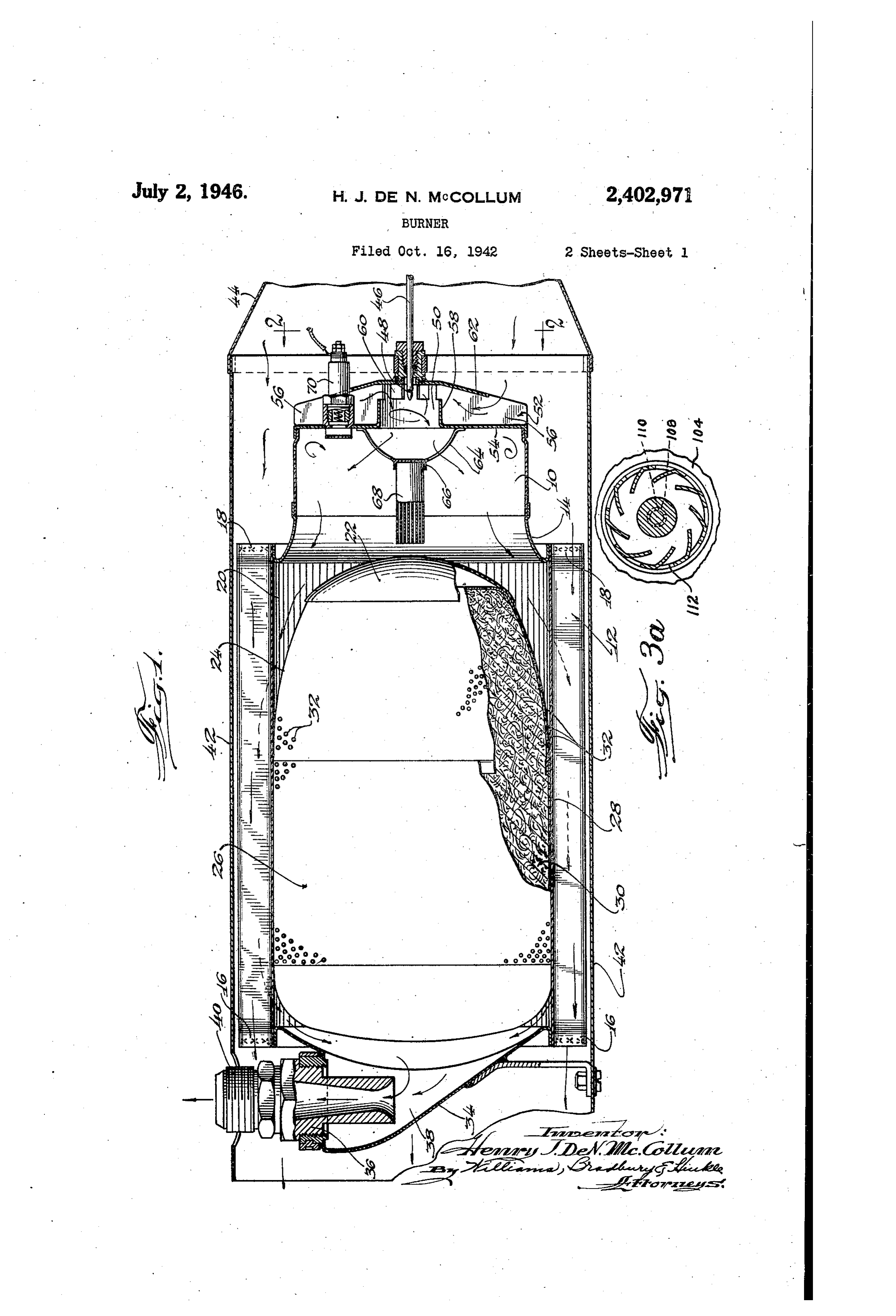
My invention relates to burners and more par bustion delivered to the heat exchanger by the ticularly to means for improving the combustion combustion chamber. The ends of the hollow in burners of the kind used in aircraft heaters and fins are pinched together and sealed by Welding for similar purposes. or in any other suitable manner, as indicated An object of my invention is to provide a burn 5 at 6 and 8, to close the ends of the passages. er of the kind adapted for use in aircraft heaters in the hollow fins.
and having new and improved means for pro The hot products of combustion from the Com viding a more intimate and homogeneous mix bustion chamber f G flow through a tapered an ture of the fuel and air. nular passage 20 surrounding the nose 22 and Another object of my invention is to provide () tapered end 24 of a muffler 26 which is located burner carbureting means wherein the air to be in the heat exchanger 2. The muffler has a mixed with fuel is preheated to provide a more sheet metal shell 28 containing sound absorb intimate and improved combustible mixture. . ing material 30, such as glass wool or stainless Another object of my invention is to provide steel wool. Openings 32 in the muffler shell form a burner having novel means for producing a 15 acoustic couplings between the gas passages and whirling motion in the comb'lsion air prior to the interior of the muffler and permit the sound its mixture with the fuel to produce a more to pass into the glass wool and be absorbed there homogeneous mixture of the fuel and air. by.
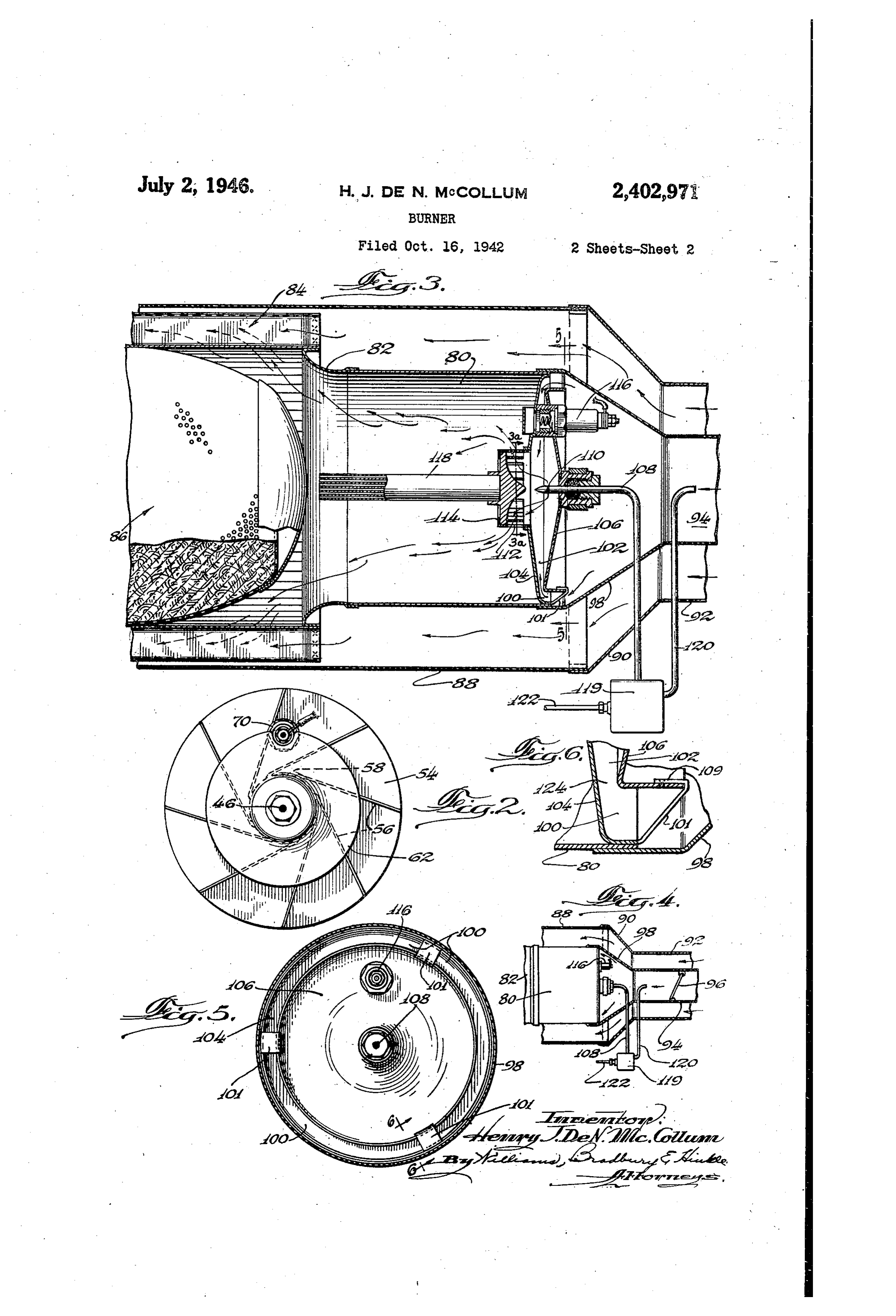
Another object of my invention is to provide The end of the tubular heat exchanger 2 which a burner having new and improved carbureting 20 is opposite to the combustion chamber 0 is closed means which is light, compact and inexpensive by a plate 38 supporting an outlet fitting 36. A and which enhances the efficiency of the burner discharge chamber 38 is located between the plate Without materially increasing its cost or weight. 34 and the adjacent, end of the muffler 26, and Other objects and advantages will become ap receives the products of combustion after they parent as the description proceeds. 25 have given up their heat to the heat exchanger . In the drawings: 2. These cooled products of combustion are Fig. 1-is a view showing a longitudinal section then discharged to atmosphere through the out of an aircraft heater embodying one form of my let fitting 36 and any suitable exhaust pipe con invention; nected to the threaded end 80 of this fitting. Fig. 2 is an end. view of the carburetor struc 30 The tubular heat exchanger and other parts ture of Fig. 1 and is taken on the line 2-2 of thus far described are enclosed in a cylindrical that figure; casing 42 which cooperates with the heat ex Fig. 3 is a view showing a partial, longitudinal changer 2 to form ventilating air passages be Section of an aircraft heater embodying a second tween and around the hollow fins. The right form of my invention; Fig. 3A is a transverse hand end of the casing 42 is connected to an air Section taken on the line 3A-3A of Fig. 3; inlet 46 which is supplied with air by a ram, Fig. 4 is a view on a reduced scale showing the blower, or other suitable air circulating means. manner in which the air is supplied to the car The ventilating air absorbs heat from the heat bureting means and the heat transfer means exchanger 2 and is discharged from the left of Fig. 3; 40 hand end of the casing 42 into the aircraft cabin Fig. 5 is an end view of the carbureting means or other space to be heated or into ventilating of Fig. 3 and is taken on the line 5-5 of that ducts for conducting this air to selected locations. figure; and I have provided novel carbureting means for Fig. 6 is a view showing a detail and is taken Supplying a homogeneous, combustible mixture to on the line 6-6 of Fig. 5. the combustion chamber 0. The fuel for this In the embodiment of Figs. 1 and 2, I have carbureting means is furnished by way of a fue illustrated an aircraft heater comprising, in gen supply pipe 66 having outlet openings 48 located eral, a combustion chamber 0 for supplying hot in the cylindrical chamber 50 of my novel car products of combustion to one end of a tubular bureting means. The pipe 86 is connected with heat exchanger 2 to which the combustion cham a pump or other suitable means which supplies ber 0 is connected by way of an outwardly far the fuel thereto under pressure at a rate which ing plate 4. The heat exchanger i 2 has hollow may be varied to conform to the particular con fins extending lengthwise thereof and the ir. ditions under which the heater is operating. An teriors of these hollow fins form longitudinally appropriate pumping apparatus is diagrammati extending passages for the hot products of con cally indicated in Fig. 3 and will be referred to
Page 4
more specifically in a description of the embodi a combustion air inlet 94 which is located in the ment shown in that figure. inlet 92, as best shown in Fig. 4. A check valve The chamber 50 is located in a structure 52 96 of the gravity operated type is located ada having a Wall 54 which forms the end wall of the cent the entrance to inlet 94 and prevents any combustion chamber 10. A plurality of vanes 56 5 fuel vapors or burned gases from escaping from are arranged tangentially with the cylindrical the combustion air inlet 94 and mixing with the wall 58 of the chamber 50, as most clearly shown ventilating air. This feature is claimed in my in Fig. 2, and serve to direct combustion air into co-pending application, Seria No. 460,969, fling this chamber through openings 60 in cylindrical date October 6, 1942, and requires no further dis- . Wa 58. 0. cussion herein.
A circular baffle 62 forms a part of the structure The combustion air which flows past the check 52 which is in the form of a casting including the valve 96 enters a conical extension 98 of the com end wall 54, the cylindrica wall 58, and the tan bustion inlet 94 and then passes through the gentially arranged vanes 56. The baffle 62 pre three arcuate inlet openings too leading to a Vents the air from entering the spaces between 15 heating and mixing chamber 02. The chamber the vanes 56 at a point adjacent the openings 60 O2 is formed between sheet metal plates O4 and leading to the mixing chamber 50. The air 06, which are secured together by fingers of which eventually reaches this chamber, there forming integral extensions of the plate 04. fore, must enter the spaces between the vanes 56 These fingers have reversely bent ends 09 which adjacent the outer ends thereof and flow in 20 may be welded, soldered, or otherwise attached wardly to the openings 60 leading to the mixing to the plate 06.
chamber 50. This particular arrangement serves Fuel is supplied to the mixing chamber 02 by a dual purpose in that the longer travel of the air a fuel supply pipe 08 having outlet openings to in contact with the vanes 56 and wall 54 preheats at approximately the center of the chamber 02. this air before it enters the mixing chamber 50. 25 The fuel is ejected from the openings to under This heated air is flowing in directions tangential pressure and in the form of a fine spray which to the cylindrical wall 58 of the mixing chamber mixes with the heated air in the chamber f02 to 50 and enters this mixing chamber with a whirl form a combustible mixture. This combustible ing motion which produces a better intermixing mixture passes through the tangentially arranged of the air and fuel and this flow arrangement 30 openings f2 in a burner tube f4 and is given a cooperates with the preheating of the air to form whirling motion as it enters the combustion a homogeneous, highly combustible mixture in the chamber 80. This whirling motion increases the mixing chamber 50. honogeneity of the mixture so that the combus The combustible mixture formed in the mixing tion chamber receives a uniform, highly com chamber 50 passes into the combustion chamber bustible mixture which is ignited by one or more through the openings 64 in a spider 66 which electrical igniters 6. A suitable reigniter f3 Supports a re-igniter 68. The combustible mix is illustrated as being mounted on the burner ture initially entering the combustion chamber ?o tube 4, is ignited by one or more electrical igniters To Fuel is forced into the fuel supply pipe O8 by mounted in the wall 54. The igniter to is con 40 a pumping apparatus 19 whose rate of fuel dis nected to a suitable source of electrical energy charge is responsive to atmospheric pressure and by way of a thermostatic switch which discon. to the velocity head of the air stream in the com nects the igniter from its source when the heater bustion inlet 94. A pipe 20 has its lower end attains normal operating temperature. The re connected to the pumping apparatus if 9 and its igniter is provided to insure maintenance of upper end located in the combustion air inlet 94 combustion after the igniter TO has been discon and directed toward the entrance to this inlet. nected from its source of current. A pipe 22 connects the pumping apparatus ffs In Figs. 3A, 4 and 5, I have illustrated a modi with a fuel tank or other suitable source of fuel fled form of my invention wherein the heater has supply. The pumping apparatus f is may be of any of the usual kinds commonly used in connec a confustion chamber 80 connected by a flared, 50 tion annular plate 82 to one end of a hollow fin heat with aircraft engine carburetors and since exchanger 84 which may be identical with the the details of this pumping apparatus form no part of my invention, further description is un heat exchanger 12 of the preferred embodiment, necessary.
A muter is located in the heat exchanger ind this muffler's may likewise be identical with The plates 104 and 06 which form the mixing the numer 26 of the previous embodiment. In and heating chamber 02 provide a relatively fact the heater of Figs. 3, 4 and 5 may be identi narrow entrance 24. For example, this entrance cal with the heater of Fig. 1, except for differ may have a width of only one-eight of an inch, ences herein shown or described. whereas the width of the heating and mixing The heat exchanger 84 is heated by the hot 60 chamber 102 opposite the inner edge of the plate Products of combustion flowing lengthwise of the fe may be three-eighths of an inch. The crowd hollow fins and transfers this heat to ventilating ing of the air through this narrow entrance, to gether with the right angle turn which the air airflowing between the heat exchangers and a cylindrical casing 88 which surrounds the heat must take in flowing into this entrance, creates a turbulence in the air as it enters the chamber exchanger and combustion chamber. The left hand end of the casing 88 may open directly into 02 which helps in forming a homogeneous mix ture between this air and the fuel sprayed from the aircraft cabin or other space to be heated or the may discharge the heated ventilating air into openings to in fuel pipe O8. This turbu a System of ducts for conducting this air to se fromlence increases the absorption of heat by the air the plate. O4 which also forms one wall of lected locations. The righthand end of the cylin 70 the combustion drical casing is connected to the conical end . in the chamberchamber 02 is 80. The mixture formed given a whirling motion of an air inlet 92 into which air is forced by by the tangentially arranged parts at the open a ran, blower, or any other suitable air circu ings 2 in the burner tube as this mixture passes lating means. into the combustion chamber and this whirling : Part of the air forced into the inlet 2 enters 5 notion increases the honogeneity of the six sy,
Page 5
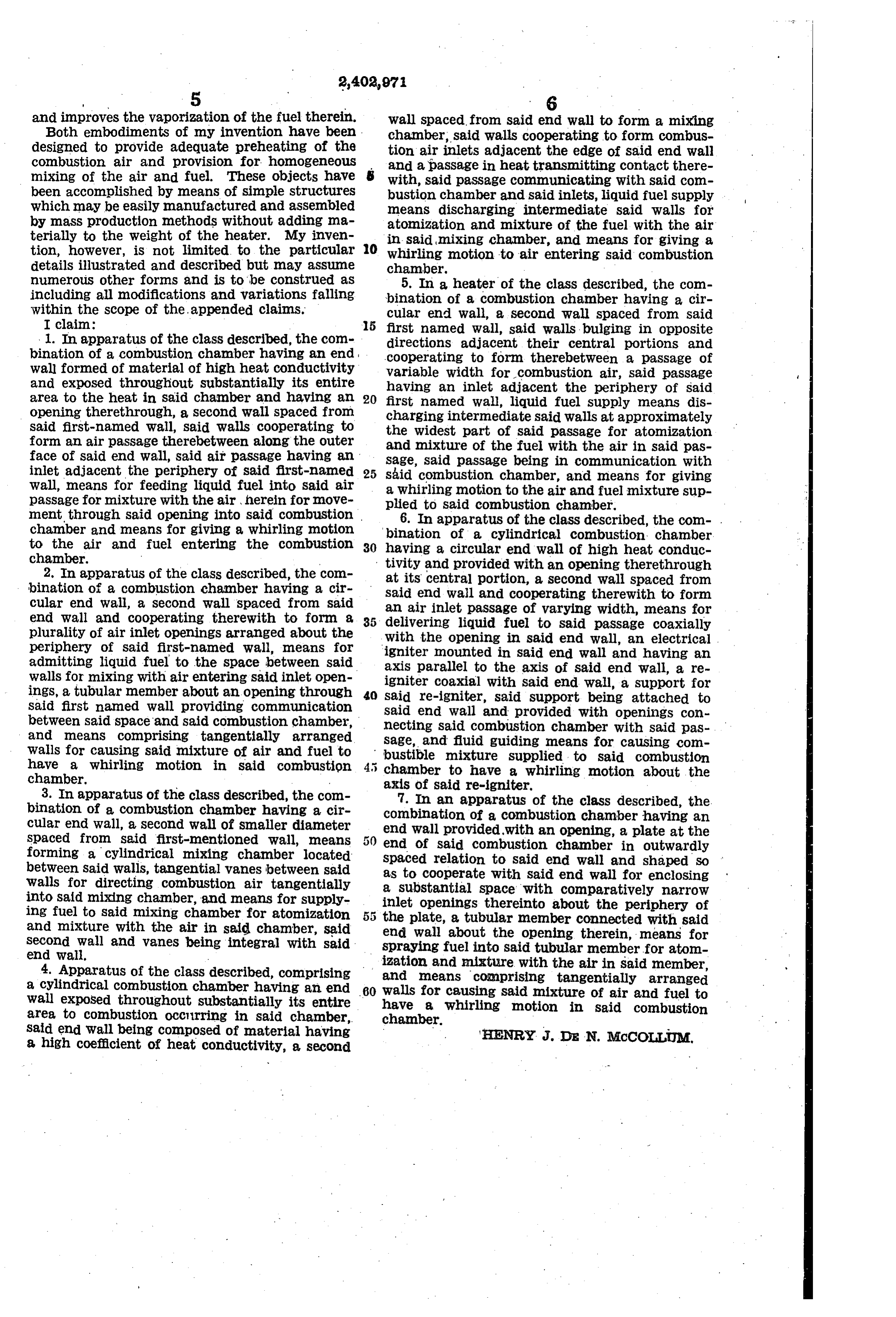
and improves the vaporization of the fuel therein. wall spaced from said end wall to form a mixing Both embodiments of my invention have been chamber, said walls cooperating to form combus designed to provide adequate preheating of the tion air inlets adjacent the edge of said end wall combustion air and provision for homogeneous and a passage in heat transmitting contact there mixing of the air and fuel. These objects have with, said passage communicating with said com been accomplished by means of simple structures bustion chamber and said inlets, liquid fuel supply which may be easily manufactured and assembled means discharging intermediate said walls for by mass production methods without adding na atomization and mixture of the fuel with the air terially to the weight of the heater. My inven 0. in said mixing chamber, and means for giving a tion, however, is not limited to the particular whirling motion to air entering said combustion details illustrated and described but may assume chamber.
numerous other forms and is to be construed as 5. In a heater of the class described, the com including all modifications and variations falling bination of a combustion chamber having a cir within the scope of the appended claims. cular end wall, a second wall spaced from Said I claim: 5 first named wall, said walls bulging in opposite 1. In apparatus of the class described, the cont directions adjacent their central portions and bination of a combustion chamber having an end cooperating to form therebetween a passage of wall formed of material of high heat conductivity variable width and exposed throughout substantially its entire having an inletforadjacent combustion air, said passage the periphery of Said area to the heat in said chamber and having an 20 first named wall, liquid fuel supply means dis opening therethrough, a second wall Spaced from charging intermediate said walls at approximately said first-named wall, said walls cooperating to form an air passage therebetween along the Outer the widest part of said passage for atomization and mixture of the fuel with the air in said pas face of said end wall, said air passage having an sage, said passage being in communication with inlet adjacent the periphery of Said first-named 25 wall, means for feeding liquid fuel into said air said combustion chamber, and means for giving a whirling motion to the air and fuel mixture Sup passage for mixture with the air herein for move ment through said opening into said combustion. plied to said combustion chamber. chamber and means for giving a whirling motion binationapparatus
of the class described, the con- .
cylindrical combustion chamber to the air and fuel entering the combustion 30 having a circular end wall of high heat conduc chamber. tivity and provided with an opening therethrough 2. In apparatus of the class described, the con bination of a combustion chamber having a cir at its central portion, a second wall spaced from said end wall and cooperating therewith to form cular end wall, a second wall spaced from Said an air inlet passage of varying width, means for end wall and cooperating therewith to form a delivering liquid fuel to said passage coaxially plurality of air inlet openings arranged about the with periphery of said first-named wall, means for igniterthemounted opening in said end wall, an electrical in said end wall and having an admitting liquid fuel to the space between said axis parallel to the axis of said end wall, a re walls for mixing with air entering said inlet open igniter coaxial with said end wall, a support for ings, a tubular member about an opening through 4. said re-igniter, said support being attached to said first named wall providing communication said end wall and provided with openings con between said space and said combustion chamber, necting said combustion chamber with said pas and means comprising tangentially arranged sage, and fluid guiding means for causing con walls for causing said mixture of air and fuel to bustible mixture supplied to said combustion have a whirling motion in said combustion 5 chamber to have a whirling motion about the chamber. axis of said re-igniter.
3. In apparatus of the class described, the com 7. In an apparatus of the class described, the bination of a combustion chamber having a cir combination of a combustion chamber having an cular end wall, a second wall of Smaller diameter end wall provided with an opening, a plate at the spaced from said first-mentioned wall, means end of said combustion chamber in outwardly forming a cylindrical mixing chamber located spaced relation to said end wall and shaped so between said walls, tangential vanes between said walls for directing combustion air tangentially as to cooperate with said end wall for enclosing into said mixing chamber, and means for supply a substantial space with comparatively narrow inlet openings thereinto about the periphery of ing fuel to said mixing chamber for atomization 5 the plate, a tubular member connected with said and mixture with the air in said chamber, said end wall about the opening therein, means for second wall and vanes being integral with said spraying fuel into said tubular member for atom end wall.
4. Apparatus of the class described, comprising ization and mixture with the air in said member, and means comprising tangentially arranged a cylindrical combustion chamber having an end 60 walls for causing Said mixture of air and fuel to wall exposed throughout substantially its entire have a whirling motion in said combustion area to combustion occurring in said chamber, chamber.
said end wall being composed of material having 'HENRY J. D. N. McCOLLUM, a high coefficient of heat conductivity, a second
Provenance
- Collection
- Cited prior art
- Original PDF
- patentimages.storage.googleapis.com →
- Filed
- 1942-10-16
- Pages
- 5
- Method
- pdftotext (the PDF's own text layer) + pdftoppm 300dpi page scans
- Source
- Google Patents bibliographic record
- Granted
- 1946-07-02
- Inventors
- Mccollum Thelma
- Transcribed from
- patentimages.storage.googleapis.com →