patent · US2401836
Means for controlling fuel combustion
11 June 1946
Page 1
Drawing sheet — no readable text.
Page 2
Patented June 11, 1946
UNITED STATES PATENT OFFICE
MEANS FOR CONTROLLING FUEL
COMBUSION
Frank W. McManus, Del Paso Heights, Calif.
Application July 13, 1942, Seria No. 450,48
My invention relates to improvements in a
nace at a point beyond where the fuel is ignited.
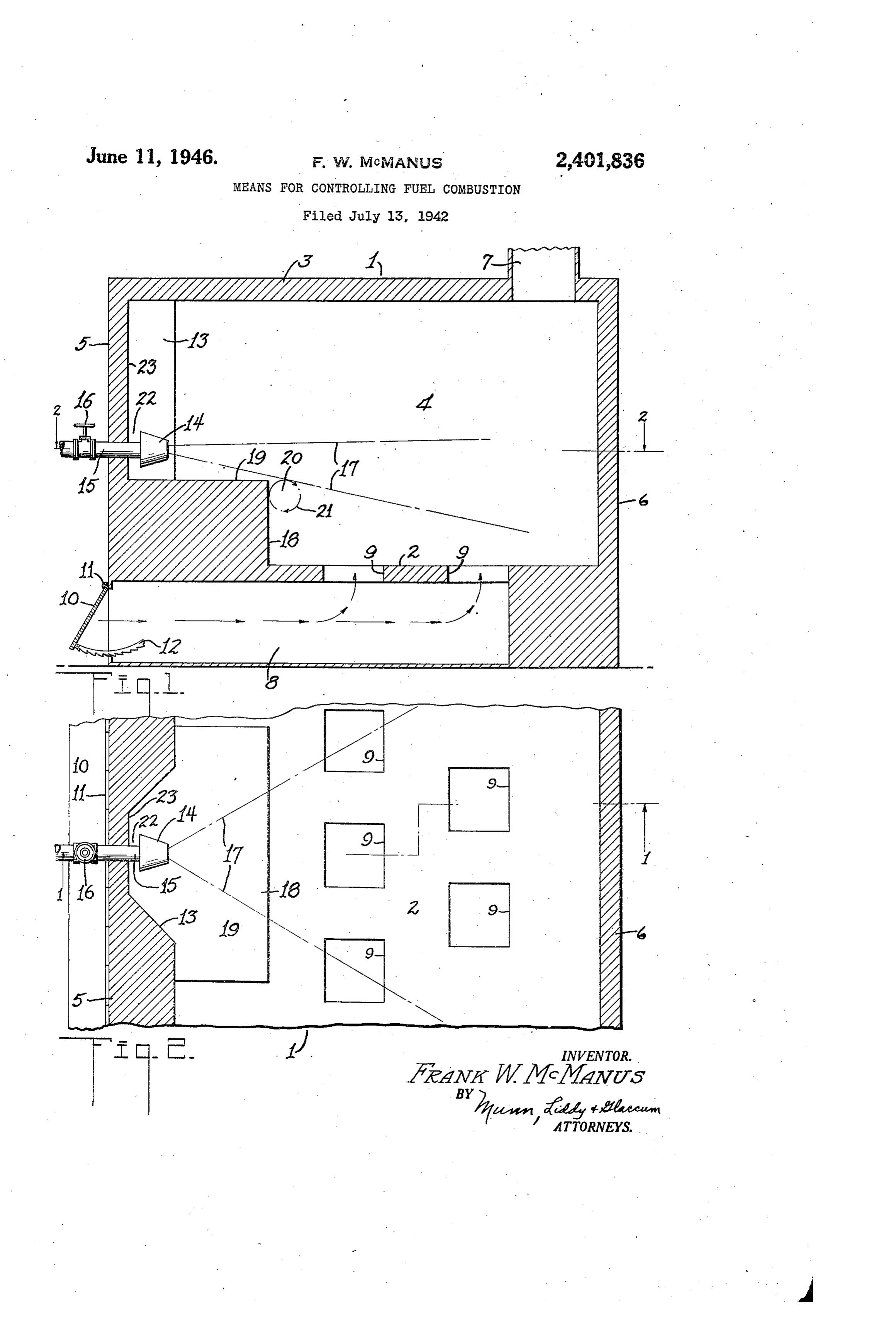
means for controiling fuel combustion, and it The amount of air entering the furnace is con consists of the combinations, constructions and trolled by means of a damper or other suitable arrangements hereinafter described and claimed. means and just enough air is admitted to insure In one of the standard types of fuel burners, complete combustion of the fuel. I have found a cone is rotated and tends to throw of oil in a that with this arrangement, the fuel is entirely radial direction. Air is forced between the cone consumed without the necessity of providing a and a housing encircling the cone, and directs target and without the necessity of providing a the fuel forwardly. The increasing of the air secondary air inlet. The amount of air enter velocity lengthens out the path taken by the fuel. O ing the furnace can therefore be materially re In addition, to the primary air, secondary air is duced and this will cause less air to pass up used to aid in the burning of the fuel. In spite through the Smoke stack with the result that of this additional air supply, all of the fuel is not practically all of the heat generated by the burn consumed and because of this, carbon deposits ing fuel, will be used and very little heat Will are built up in the furnace aEd these must be 5 escape through the chimney. The air entering renaoved from time to line. this type of the furnace can either be controlled as it enters surner, 3, target is used against which the by means of a damper, or a damper may be placed atomized fuel is projected and the fuel is ignited in the chimney and control the foW of the burnt at the tsarget. It is impossile to ignite the fuel products out through the chinney. at 2ny point, on the time it, leaves the cone The device is extremely simple in construction until it strikes the target, because the speed of and is durable and efficieza, for the purpose in the fell preveats it is or being set on fire at or tended. It is designed to burn any kind of fuel Aes he nozzle. - Such as oil, gas, powdered coal, etc. Arother standard type of fuel burner nakes Other objects and advantages Will appear in Age of an oil atomizer with a signal difice through the following specificatio2, and the novel fea Syaica the oil is forced. A strean of pri aay air tires of the device Will be particularly, pointed ?eaVeiogs the storalizer and is a ced With he out in the appended clerns. gonged fuel to for a cornustiole initie. lity invention is illustrated in the accompany Rae pinnery air is Wied and it earries the Suel ing drawing forning a part of this applicatios, in at such a speed tag?, 9 ig Raiting of the fuel at . 3 c the 8tonizer is irageSSle. The atoirized fuel Figure 1 is a Vertical section along the line and grizinary air 28 g:lected against & target 2-8 of Sigure 2; and in a nicked state and 8; this place ignition takes . Figure 2 is a horizontal section along the line place, Secords, air is also used in this type of 2-3 of Figure , tourne, oi, aver with this additional air, the 36 In carrying out my inventiora, i giovide a fur conglete fougairag of the fuel is impossible. nace indicated generally at A, this furnace has a The grincips object of any iVeration is to proa botton wall 2, a top wall 3, side walls 3 and end wide a means for forraing a partial Vacra Knear Wells and S. A chiney leads from the top the fuel nozzle, that will form a zone of relan Wall 3 and an air iuct 8 leads under the cottom tively alovy anowing contoustible mixture adjacent Wall 2 to openings S in the botton wall or fur to the rapidly moving strean of fuel projected nace floor 2. An adjustable diaper 8 is hinged from the nozzle. I have found that these sRaall at . . and controls the flow of air into the dict edicy currents of fei in the zone of partial 3. The damper Gnay be adjusted by any nee, as yacaula may be ignited and will coatinue to burn Such as by 3 pivoted rack 2.
at gaite the more rapidly moving main fuel 3. The end wall 5 has a recess S, see Figare 2, column. In this way it is possible to ignite the and in this recess mount, a fuel outlet no.22e 86. fuel at a place near the gaozzle instead of igniting A pipe 85 continuanicates with the nozzle, and a the fis at a, age disposed at the Opposite end Valve 3 controls the flow of fuel to the O23e. of the 3race frontine nozzle. The fuel is placed under pressure by any Eleans, Tae Ozzie is placed close to a wall of the fur SC not shown, and the nozzle is so designed that, nace art direct an atomized strean of fuel across the fuel Will issue therefrom approximately with a step and toward the opposite end of the fur in the area shown by the broken lines in oth nace. The fuel as it leaves the nozzle need not figures. The fuel issuing from the nozzle inay be mixed with primary air. The air that is mixed be of any type such as oil, gas, powdered coal, with the she enters from the bottom of the fur- BS etc.
Page 3
It will be noted from Figure 1 that the nozzle poses. Another feature is the provision of a par d4 is positioned directly above a step 8 and the tial Vacuum formed by the gas and the flane top 9 of the step is placed just below the lower passing over the step 8. This vacuum will cause most portion of the fuel spray of any combustible eddy currents to form adjacent to the step and mixture. The flow of fuel over the step 8 will these eddy currents of fuel will continually burn create a partial vacuum adjacent to the top so that they will ignite all of the fuel as it passes. corner of the step as indicated at 20, and small over the step. This will cause the fuel to burn eddy currents will be formed at the point of at a point much nearer the nozzle than is now vacuum as indicated by the circle of arrows 2. the practice where targets 2re used and there Another partial Vacuum Will be created at the 0. fore burning of the fuel in the furnace Will com point 22 which is disposed between the nozzle mence sooner and complete combustion will take and the inner Surface 23 of the recess 3. Figure place before the products enter tine chimney. The 2 clearly shows that the wall 5 is free from any reducing of the air fioW into the furnace Will re . air inlets. The usual practice with standard duce the velocity of the products of combustion burners is to provide air inlets adjacent to the 6 as they pass through the furnace. The burning burners. The partial vacuum at 22 created by period in the furnace will therefore be prolonged and most of the heat will be given off within the the fuel issuing from the nozzle will cause some of the air entering the openings 9 to flow to the furnace rather than within the chimney. All of recess 3 and then this air will be entrained by these advantages go to produce a far. Inore eff the flow of fuel so as to aid in making a con 20 cient combustion of fuel in the furnace and the bustible mixture, giving off of heat by the fuel than is now the From the foregoing description of the various practice.
parts of the device, the operation thereof may While I have shown only the preferred form be readily understood. of my invention, it should be understood that The valve 6 and the damper are adjusted 25 various changes or modifications may be made SO that the correct amount of fuel and air Will within the scope of the appended claims without enter the furnace. The fuel issuing from the departing from the spirit of the invention. nozzle may be ignited at the place of partial vac I claim:
uum 2 in any manner desired, such as by plac 1. The combination with a combustion cham ing a burning rag adjacent to the point 2 or by S ber having walls and a fuel inlet nozzle for pro using a Spark plug, not shown, at this place and jecting a stream of fuel under pressure into the causing a Spark to ignite the fuel. chamber, of a step having a flat surface disposed Once the fuel is ignited, a pilot flame or a low close to and paralleling the nozzle axis and a flame will continue to burn at the point 26 regard second surface extending substantially at right less of the force of the flow of fuel issuing from 35 angles to the flat surface to provide a recess the nozzle. This is the principal feature of my which defines a low pressure zone near the path invention. The pilot or a low flame at the point taken by the moving fuel stream, this low pres 20 will continue to ignite the fuel as fast as it sure zone being continually fed by fuel from the passes the step 8. The step 8 prevents the fuel stream, whereby the fuel in the low pres partial vacuum point 20 from being carried along 40 sure zone when ignited will continue to burn and with the rush of the fuel. The fuel is ignited act as a pilot flame for continually igniting the Sooner by this arrangement than where a target main fuel stream at a point near the nozzle, and is used. adjustable means for feeding air into the cham I have found that it is this arrangement that 65 ber at a point beyond the low pressure Zone for causes the fuel to burn not only without the assuring complete combustion of the fuel in the necessity of a target, but also without the ne chamber before the fuel strikes the chamber walls. cessity of providing a secondary air inlet. This 2. The combination with a combustion cham reduces the amount of air entering the furnace ber having a fuel inlet nozzle for projecting a and therefore less air in the furnace need be stream of fuel under pressure into the chamber, heated and less air will pass out through the of a step provided in the chamber and adjacent chimney. Only enough primary air is permitted to the nozzle, said step having a flat surface to pass the damper 0 to cause a complete com extending up to the nozzle and paralleling the bustion of the fuel. From actual practice, I have nozzle axis and having a second surface extend found that the fow of the burning fuel after it SS ing substantially at right angles thereto to pro has been ignited by the pilot flame at the point vide a recess, the fuel when projected across the 20, will be toward the wall 6 and at a slow speed. corner formed by the two surfaces creating a This will give the fuel ample time to be con low pressure Zone in the recess and near the pletely burned before it reaches the chimney , path taken by the moving fuel, whereby said low and therefore the heating efficiency of the fur pressure zone is continually fed by fuel from nace will be materially increased. the fuel stream, whereby the fuel in this Zone The principle involved in the device is to pro when ignited, will continue to burn and act as vide the minimum amount of air entering a fur a pilot flame for continually igniting the main nace so as to insure a complete combustion of the fuel Without the necessity of heating air in the fuel stream at a point near the nozzle. furnace that is unnecessary for combustion pur FRANK W. McMANUS. .
Provenance
- Collection
- Cited prior art
- Original PDF
- patentimages.storage.googleapis.com →
- Filed
- 1942-07-13
- Pages
- 3
- Method
- pdftotext (the PDF's own text layer) + pdftoppm 300dpi page scans
- Source
- Google Patents bibliographic record
- Granted
- 1946-06-11
- Inventors
- Frank W Mcmanus
- Transcribed from
- patentimages.storage.googleapis.com →