patent · US2333531
Furnace
2 November 1943
Page 1
Drawing sheet — no readable text.
Page 2
Patented Nov. 2, 1943 2,333,531
UNITED STATES PATENT office
FURNACE
William Ferguson, Philadelphia, Pa., assignor to
National Airoll Burner Company, Incorporated, a corporation of Delaware
Application December 30, 1941, Serial No. 424,961
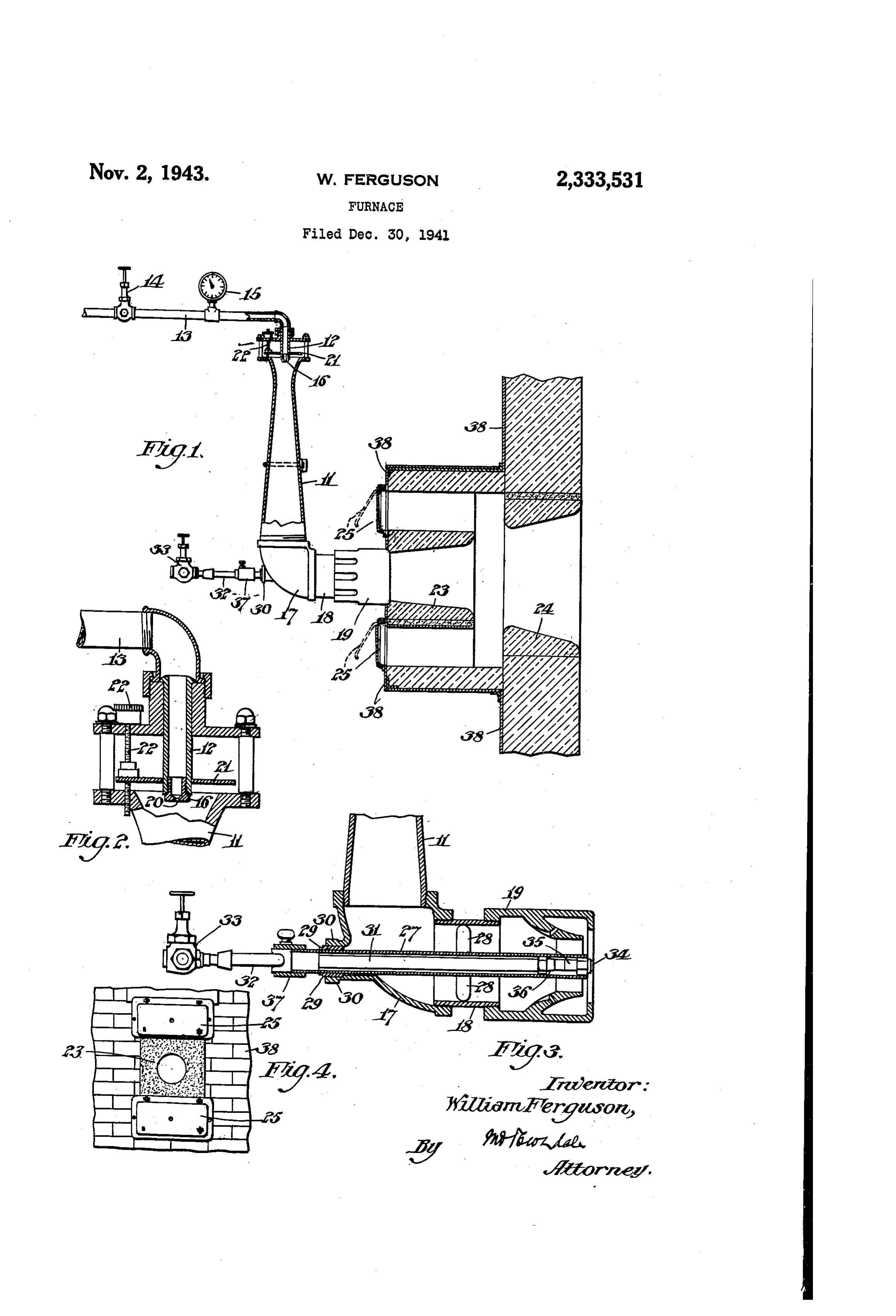
The invention relates to furnaces. Fig. 1 is a vertical section in part elevation The object is to provide method and means for showing the airovent fuel gas burner of usual facilitating the COmbustion of fuel gas and atom inspirating type.
ized fuel oil, either separately or combined, with Fig. 2 is a fragmentary sectional detail of the maximum heating efficiency. 5 fuel gas inlet end of the burner, on an enlarged The invention relates especially to a fuel gas Scale.
burner and an atomizing fuel oil burner com Fig. 3 is a fragmentary sectional view, also on bined, in a single structure and adapted to burn an enlarged scale, showing the steam atomizing both of said fuels at the Same time or to burn fuel oil burner combined with the fuel gas burner either fuel separately. 0. structure.
The invention comprises improved method and Fig. 4 is a fragmentary elevation. means whereby the flame of the fuel gas is pro Similar numerals refer to similar parts jected into the furnace, while atomized fuel oil throughout the several views. is projected into the gas flame, and whereby a The airoVent fuel gas burner is of the usual percentage of the required combustion air is en 5 inspirating type, using a Venturi tube , through trained through the burner to be mixed with the which from 40 to 90% of the total required com. atomized fuel oil, and whereby secondary com bination air is inspirated by means of the gas bustion air, under adjustable control, is delivered pressure.
to said fuel at a point adjacent the point of entry The gas is delivered through the tubular body of the fuels to the furnace. 20 2 connected to a fuel gas supply pipe f3. This The invention also comprises improved method pipe 3 is preferably provided with a suitable gas and means whereby the delivery of secondary air valve 4 and also a pressure gage 5. is subjected to such control as to deliver it pre The tubular body 2 is provided at its dis dominately in different horizontal planes. charge end with a gas orifice formation 6 pro The invention also comprises improved method vided with a discharge orifice 20. and means whereby the several flows of fuel gas, The venturi is connected at its discharge end fuel oil, preliminary combustion air and second to an elbow 7, to which is connected a pipe or alry air are all Subject to independent control for nipple 8, the axis of which is at right angles to whatever coordination desired. the axis of the venturi. The nipple 8 delivers to The invention also comprises means forming a 30 and through the flame retention nozzle 9 which nozzle common to the discharge of both fuels, and is secured on the pipe nipple f8. SO formed as to prevent flame flare-back in the The elbow connection with the venturi makes gas burner and at the same time retaining igni it possible to keep the burner close to the furnace tion, Said flame retention nozzle so constructed as Wall.
to protect the burner parts from destructive heat radiation. The intake end of the Venturi burner , into which the gas orifice is discharges, is provided
The invention also comprises improved method with an air shutter 2 which is adjustable by and means whereby a hot zone is created into means of the knurled headed screw 22, for con which the combustible mediums are projected, for trolling the amount of inspirated air which is stimulating the mixing of the fuel with secondary 40 mixed with the fuel gas within the burner tube. combustion air. The flame retention nozzle or burner head 9 The invention also comprises a burner block delivers the gas flame from the Venturi burner and a muffle block in tandem and adjustable tube to the burner block 23, and is adapted to means for delivering secondary air to said blocks, avoid the flare back in the gas burner and at the said delivery predominating in different areas, Same time maintaining ignition. This burner (such as upper and lower) of said blocks. block also insulates the nozzle (9 from excessive The invention also comprises means, such as a and destructive heat radiation. tubular housing permanently fixed within the When gas is burned, as already stated, it will airovent burner structure for receiving the fuel inspirate from 40 to 90% of the total required oil burner pipe, and for permitting its withdrawal 5) combustion air through the venturi , and dis at any time without interfering with the opera charge it through the flame retention nozzle 9 tion of the fuel gas burner. into the burner block 23, whence the flame is pro Referring to the drawing, which illustrates jected into and through the muffle block 24 to the merely by way of example, suitable means for the furnace, while secondary air, in the necessary embodiment of my invention: 55 Volume to complete combustion, is admitted
Page 3
through the adjustable secondary air doors 25 in end of the burner block and with the intake-end the front wall 38 of the furnace, of the mule.
In combination with the airoVent gas burner 2. A combined gas and oil burner, compris I have provided a fuel oil burner or oil burning ing a tubular body, means for introducing gas means associated with the structure of the gas and primary air into the intake end of said body, burne, a burner head at the other end of said body, In the example shown herein I have provided a an oil atomizer delivering to the region of dis steel tube 2 extending axially through the elbow charge of the burner head, a burner block for re f7, nipple f8 and flame retention nozzle 9, to or ceiving the discharge from the burner head, a near the discharge end of said nozzle 9. This O chamber for secondary air open to the discharge tube 2 is permanently supported and centered end of the burner block, said chamber provided by the four centering spokes, as at 28, in the nip with air-inlet ports and adjustable closures there ple 8 midway its extension; and near its outer for, and a muffle block spaced from and co-axial end is supported and positioned by the bushing With the burner block for receiving and deliver 29, in the wall 30 of the elbow T-said steel tube s ing the discharge from the burner head mixed extending Outwardly beyond the wall of the el With the said secondary air. bow. This steel tube 27 is adapted to receive the 3. A combined gas and oil burner, comprising fuel oil burner pipe 3f, which is connected with a tubular body, means for introducing gas and an oil supply pipe 32, controlled by the oil regul primary air into the intake end of said body, a lating valve 33. This oil burner pipe 3 extends 20 burner head at the other end of said body, an oil through the steel pipe 2 and has its discharge atomizer delivering to the region of discharge end or nozzle 34 in or near the plane of the dis of the burner head, a burner block coaxial with charge end of the flame retention nozzle or the burner head, and positioned to receive the burner head 9. Suitable formations such as 35, discharge from the said burner head, a muffie 36, serve to center the oil burner pipe 3 in said 25 block Spaced from, and positioned coaxially with steel pipe or sleeve 2 near the nozzle end. A the burner block to receive the discharge from suitable adapter 37 is provided for securing the said burner block, and a secondary air chamber proper relationship between the steel tube 2 and delivering to said muffle, said chamber surround the Outer end of the oil burner pipe 3. This ing the burner block and partaking of the heat arrangement makes it possible to insert the oil 30 therefrom, burner pipe in, or withdraw it from, the steel 4. A combined gas and oil burner, comprising tube 2 without disturbing the operation of the a tubular body, means for introducing gas and gasfuel burner. primary air into the intake end of said body, a If fuel oil is being burned, it is estimated that burner head at the other end of said body, an possibly 5 to 10% of the combustion air is drawn 35 oil atomizer deiivering to the region of discharge through the gas burner, and the remaining 90% of the burner head, and a tubular housing in or more is admitted through the secondary air fixed axial relationship with the burner head doors 25, so that regardless of which type of fuel and adapted to receive the oil atomizer and per is being burned, the combustible mixture or nit its insertion and withdrawal in and from the fame, leaving the muffle block into the furnace 40 housing without disturbing the operation of the has approximately the same proportion of air, gas fuel burner.
which in some types of furnace may be as low as 5. A combined gas and oil burner, comprising 10% above theoretical requirements. a tubular body, means for introducing gas and In addition to the features of the accurate Con primary air into the intake end of said body, a trol of primary and secondary air, regardless of 45 burner head at the other end of said body, an kind of fuel being burned, the combination of oil atomizer delivering to the region of discharge burner block and muffle block Creates a hot ZOne of the burner head, a burner block co-axial with to stimulate the mixing of the gaseous fuel Or the burner head, and positioned to receive the atomized oil with the secondary air for the pur discharge from the said burner head, a muffle pose of obtaining an efficient and stable fire. 50 block Spaced from, and positioned co-axially with Applicant does not know of any other such the burner block to receive the discharge from combination of atomizing fuel oil burner and in Said burner block, and a secondary air chamber spirating gas burner which will give equal com delivering to said muffle, said chamber surround bustion results throughout a wide range in ca ing the burner block and partaking of the heat pacity. Heretofore combination burners have 55 therefron.
functioned fairly satisfactorily as inspirating gas 6. A combined gas and oil burner, comprising burners only, but the fuel oil burner feature was a tubular body, means for introducing gas and not satisfactory in that it was not possible to op primary air into the intake end of said body, a erate on as small a quantity of combustion air burner head at the other end of said body, an with fuel oil as with fuel gas. Also, the oil fire 60 oil atomizer delivering to the region of discharge caused smoke and was very unstable in its oper of the burner head, a burner block co-axial with ation due to poor mixing of atomized oil and the burner head, and positioned to receive the combustion air. discharge from the said burner head, a muffle What I claim is: block Spaced from, and positioned co-axially with 1. A combined gas and oil burner, comprising 65 the burner block to receive the discharge there a tubular body, means for introducing gas and from, and a secondary air chamber delivering primary air into the intake end of said body, a to said muffle, said chamber provided with air burner head at the other end of Said body, an intake Openings above and below said burner oil atomizer delivering to the region of discharge block with independently operated closures of the burner head, a burner block for receiving O therefor as means whereby the secondary air the discharge from the burner head, a chamber may receive different degrees of heat at selected for secondary air and a muffle block Spaced from Zones, before entering the muffle block. and coaxial with the burner block, said chamber being in open communication with the discharge WLLAM FERGUSON.
Provenance
- Collection
- Cited prior art
- Original PDF
- patentimages.storage.googleapis.com →
- Filed
- 1941-12-30
- Pages
- 3
- Method
- pdftotext (the PDF's own text layer) + pdftoppm 300dpi page scans
- Source
- Google Patents bibliographic record
- Granted
- 1943-11-02
- Inventors
- Ferguson William; NAT AIROIL BURNER Co Inc
- Transcribed from
- patentimages.storage.googleapis.com →