patent · US1591891
Apparatus for burning fuel oil
6 July 1926
Page 1
Drawing sheet — no readable text.
Page 2
Drawing sheet — no readable text.
Page 3
Drawing sheet — no readable text.
Page 4
Patented July 6, 1926. 1,591,891
UNITED STATES PATENT OFFICE.
MAX SKLOVSKY, OF MOLINE, ILLINOIS, ASSIGNOR. To DEERE & comPANY, of MoRE,
ILLINOIS, A CORPORATION OF LILINOIS. .
APPARATUS FOR BURNING FUEL or L.
Application filed March 19, 1920. Serial No. 367,152,
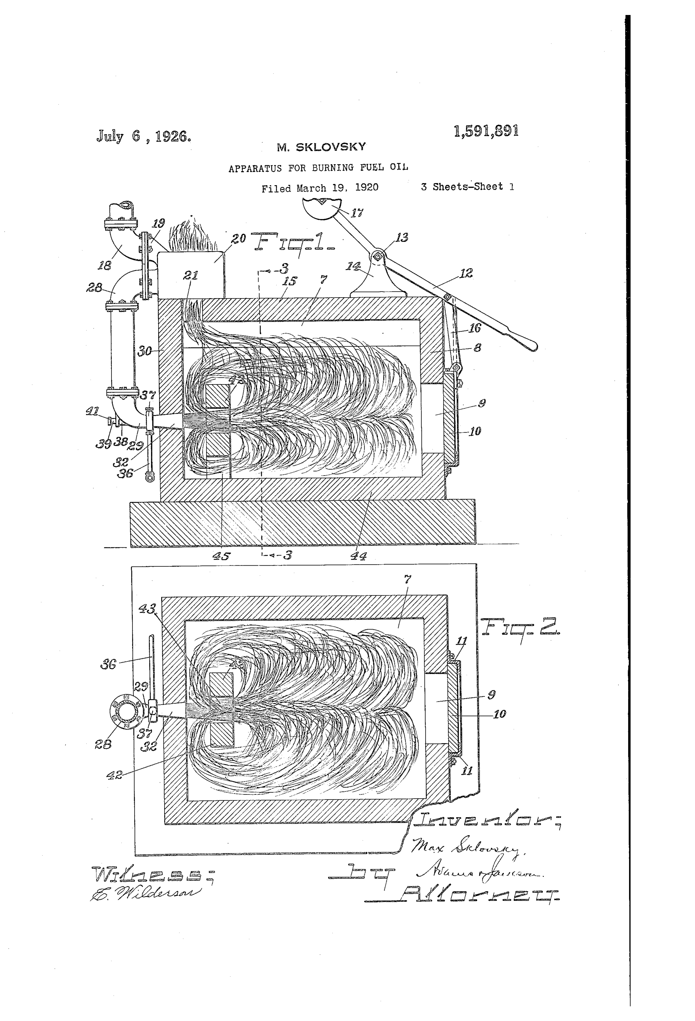
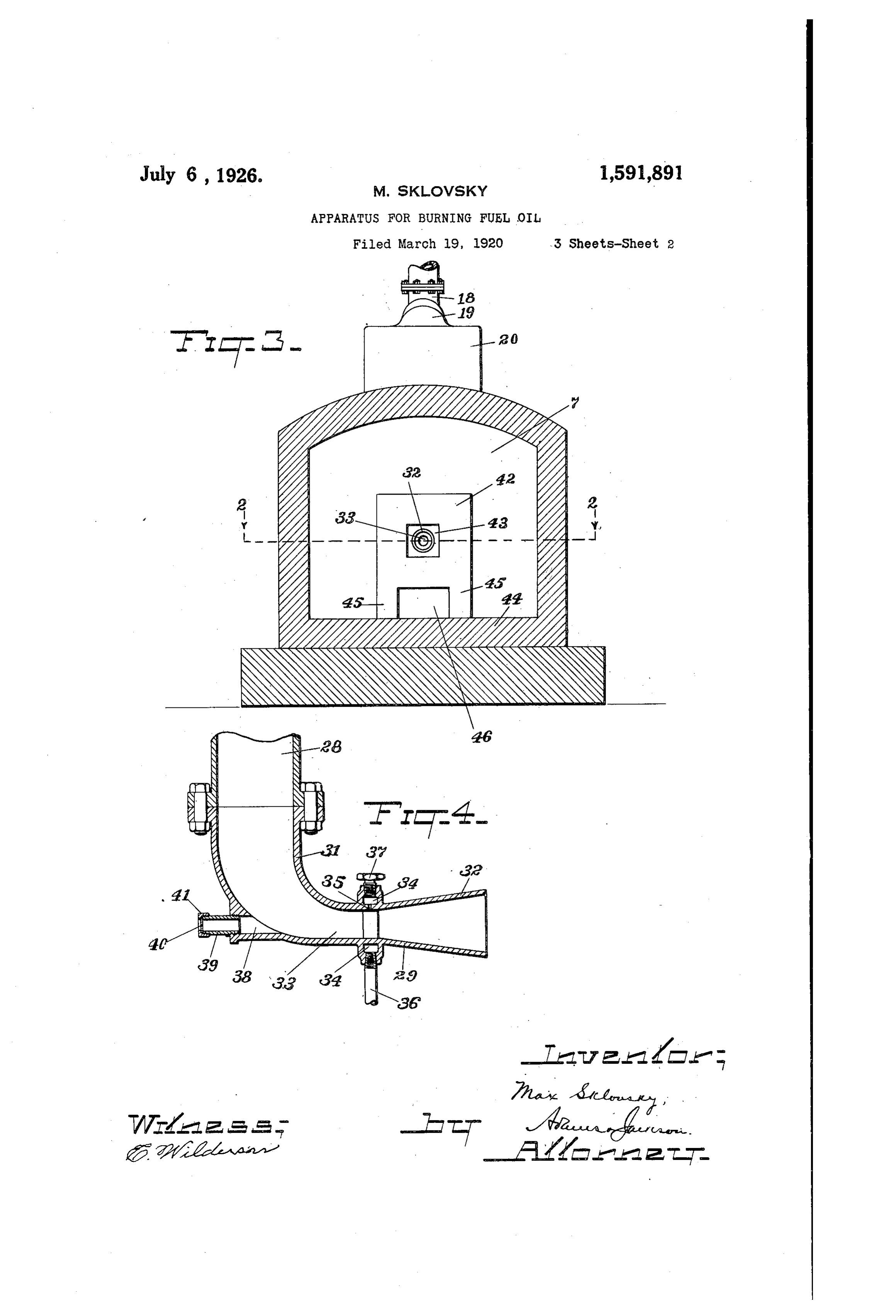
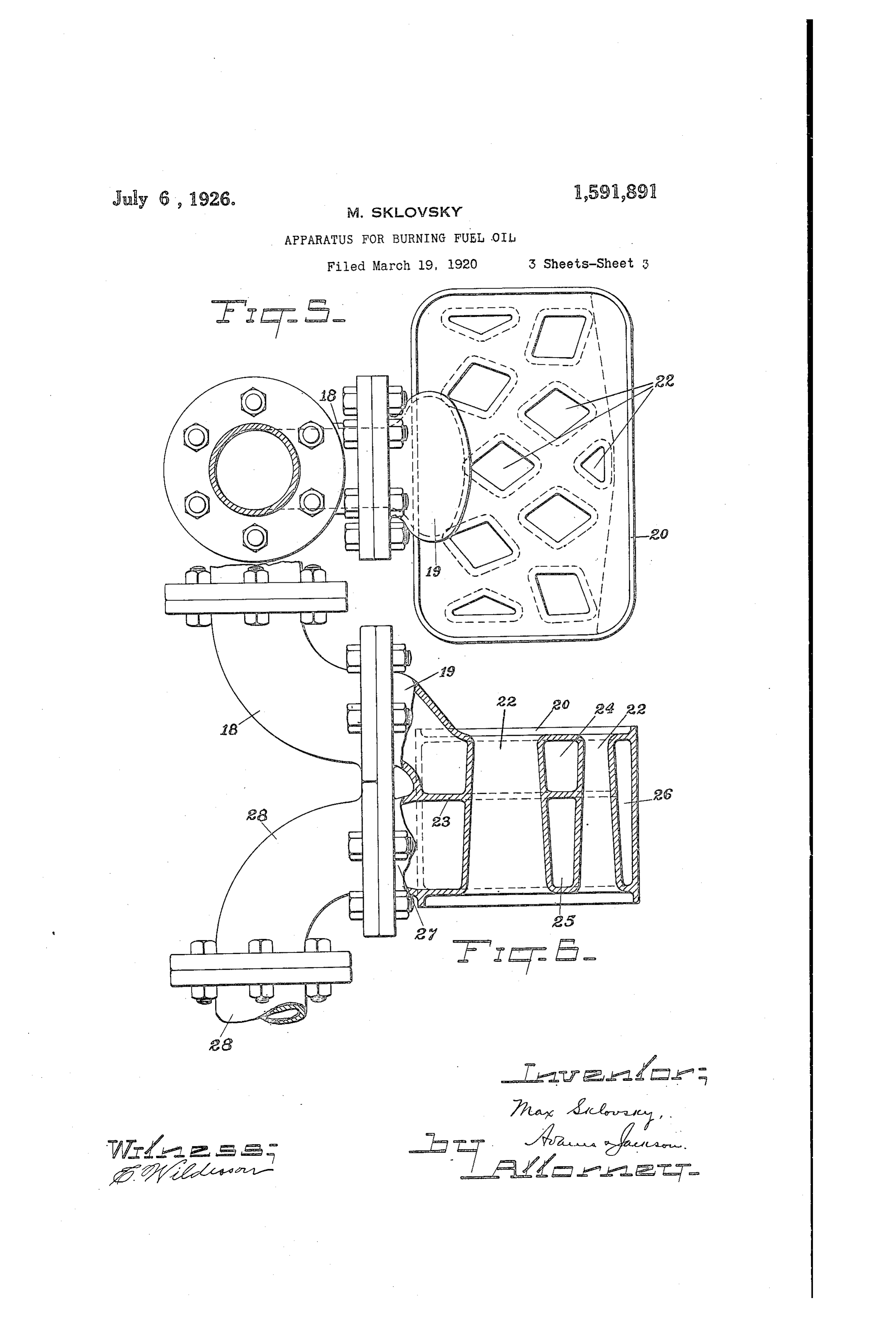
My invention has to do with heating ator to a greater or less extent of the weight metallurgical furnaces to the requisite high of the door. SS temperature by the use of fuel oil or other 18 indicates an air supply pipe which is equivalent fuel, and has for its object to connected with a fan or other means of provide an improved apparatus by which Supplying air under pressure. Said pipe is the desired high temperature may not only Connected to a tubular connection 19 E. be obtained, but may also be maintained forms a part of an air heater 20 mounted 60 without material variation, and by which upon the upper wall 15 of the furnace over also the temperature may be accurately reg an opening 21 placed adjacent to the left O ulated and the furnace be economically hand end of the furnace as viewed in Fig. operated both as regards fuel consumption 1, which is the end at which the fuel is in and care of an attendant. I accomplish troduced, as will be hereinafter explained. 65 this object as illustrated in the drawings and The construction of the air heater 20 is as hereinafter described. What I regard best shown in Figs. 5 and 6, from an in 5 as new is set forth in the claims. Spection of which it will be seen that said In the accompanying drawings which il heater is a casting having a series of ver lustrate the preferred embodiment of my tical passages 22 therethrough which when 70 invention the heater is in position overlie the passage Fig. 1 is a longitudinal vertical section of 21 So that waste gases passing out of the 20 a metallurgical furnace, the air heater and combustion chamber 7 are discharged fuel pipes being shown in elevation, and through the passages 22. The interior of 75 some parts also being broken away; the heater 20 around the passages 22 is di Fig. 2 is a horizontal section on line 2-2 vided intermediately by a horizontal par of Fig. 3; tition 23 into upper and lower ducts 24-25 25 Fig. 3 is a vertical cross-section on line which are connected at the side farthest 3-3 of Fig. 1; from the connection 19 by a vertical duct Fig. 4 is an enlarged detail, being a par 26, as shown in Fig. 6. The lower duct 25 80 tial vertical section of a fuel nozzle; communicates with a circular connection Fig. 5 is a plan view of the air heater, 2 which is adjacent to and preferably in 30 showing in section the pipe which supplies alinement with the connection 19, as shown the same; and in Figs. 1, 5 and 6. The arrangement of Fig. 6 is a side elevation showing the air the ducts 24-25 is such that air entering 85 pipes connected with the heater, which is the duct 24 through connection 19 is dis shown principally in section. tributed through the upper portion of the 35 Referring to the drawings heater until it passes to the vertical duct 7 indicates a combustion chamber which 26 when it is in like manner caused to travel may be of any suitable shape, but is pref through the lower duct 25 to the connection 90 erably a square compartment having en 27 from which it is discharged into a hot closing walls of fire brick. In one of the air pipe 28, as best shown in Fig. 6. Thus 40 end walls, 8, is an opening 9 through which the waste gases, which are at a high tem the materials to be heated may be intro perature, in escaping through the openings 95 duced, said opening being adapted to be or passages 22 raise the.heater 20 to a high closed by a door 10 of any suitable de temperature, and consequently highly heat scription. In the construction illustrated the air flowing through it. The arrange 45 said door is adapted to slide vertically in ment of the connections 19 and 27 provides guides 11 at opposite sides of the door open a convenient way of connecting them to the ing, as shown in Fig. 2, and is operated by pipes 18 and 28, permitting the heater to O a lever 12 fulcrumed at 13 upon a standard be cast as an integral device. 14 mounted on the upper wall or roof 15 of The hot air pipe 28 leads to a nozzle 29 50 the combustion chamber, as best shown in fitted in a suitable opening in the end wall Fig. 1. The lever 12 is connected to the 30 of the furnace, as shown in Fig. 1, so door 10 by a link 16 and is provided with that hot air may be discharged through it OS a counterbalance 17 for relieving the oper into the combustion chamber. The nozzle
Page 5
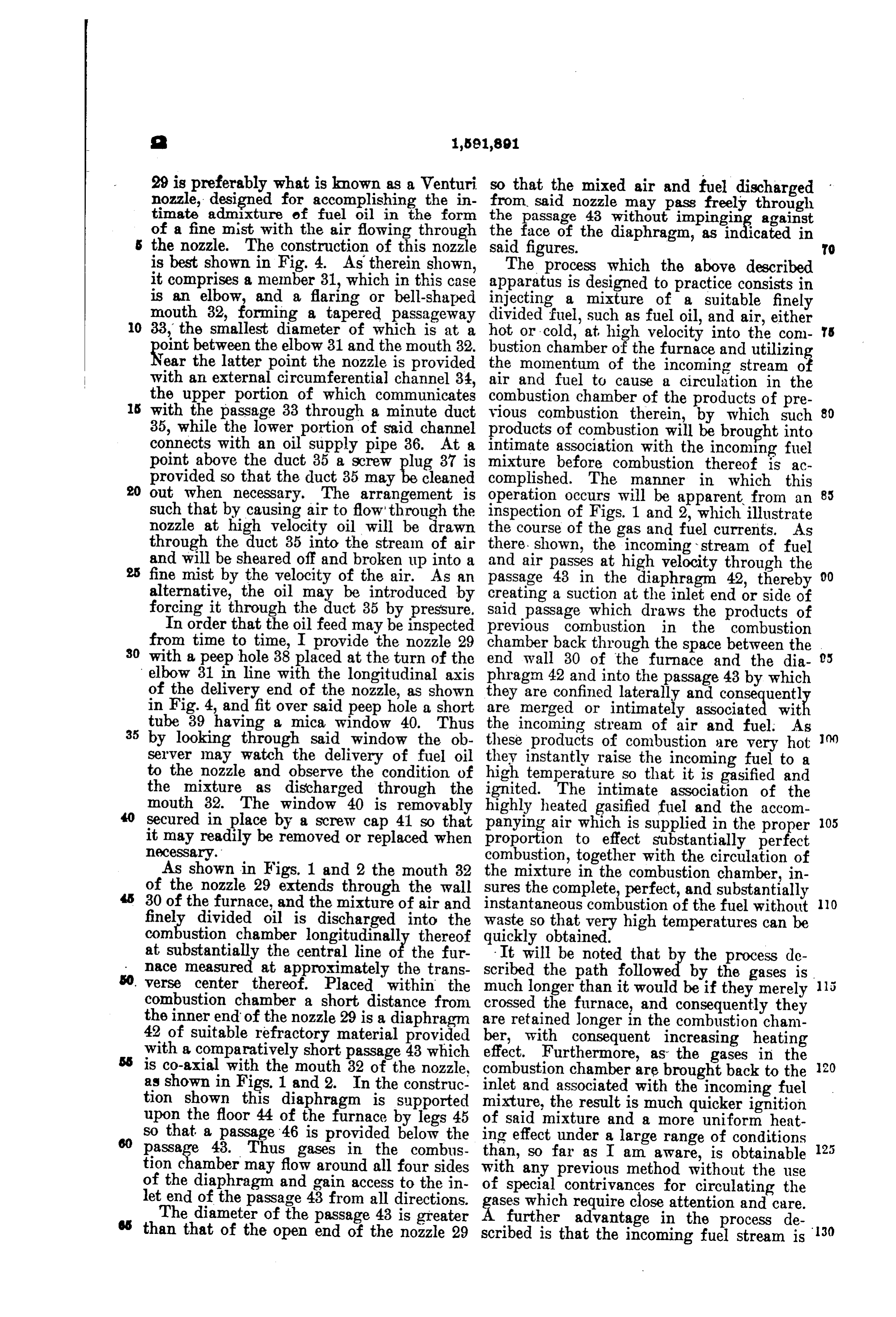
29 is preferably what is known as a Venturi so that the mixed air and fuel discharged nozzle, designed for accomplishing the in from said nozzle may pass freely through timate admixture of fuel oil in the form the passage 43 without impinging against of a fine mist with the air flowing through the face of the diaphragm, as indicated in the nozzle. The construction of this nozzle said figures. TO is best shown in Fig. 4. As therein shown, The process which the above described it comprises a member 31, which in this case apparatus is designed to practice consists in is an elbow, and a flaring or bell-shaped injecting a mixture of a suitable finely mouth 32, forming a tapered passageway divided fuel, such as fuel oil, and air, either 0 33, the smallest diameter of which is at a hot or cold, at high velocity into the com s oint between the elbow 31 and the mouth 32. bustion chamber of the furnace and utilizin Near the latter point the nozzle is provided the momentum of the incoming stream o with an external circumferential channel 34, air and fuel to cause a circulation in the the upper portion of which communicates combustion chamber of the products of pre s with the passage 33 through a minute duct vious combustion therein, by which such 80 35, while the lower portion of said channel products of combustion will be brought into connects with an oil supply pipe 36. At a intimate association with the incoming fuel point above the duct 35 a screw plug 37 is mixture before combustion thereof is ac provided so that the duct 35 may be cleaned complished. The manner in which this 20 out when necessary. The arrangement is operation occurs will be apparent from an 85 such that by causing air to flow through the inspection of Figs. 1 and 2, which illustrate nozzle at high velocity oil will be drawn the course of the gas and fuel currents. As through the duct 35 into the stream of air there shown, the incoming stream of fuel and will be sheared off and broken up into a and air passes at high velocity through the fine mist by the velocity of the air. As an passage 43 in the diaphragm 42, thereby 00 alternative, the oil may be introduced by creating a suction at the inlet end or side of forcing it through the duct 35 by pressure. Said passage which draws the products of In order that the oil feed may be inspected previous combustion in the combustion from time to time, I provide the nozzle 29 30 with a peep hole 38 placed at the turn of the chamber back through the space between the 05 end wall 30 of the furnace and the dia elbow 31 in line with the longitudinal axis phragm 42 and into the passage 43 by which of the delivery end of the nozzle, as shown they are confined laterally and consequentl in Fig. 4, and fit over said peep hole a short are merged or intimately associated wit tube 39 having a mica window 40. Thus 35 by looking through said window the ob the incoming stream of air and fuel. As these products of combustion are very hot server may watch the delivery of fuel oil they instantly raise the incoming fuel to a to the nozzle and observe the condition of high temperature so that it is gasified and the mixture as discharged through the ignited. The intimate association of the mouth 32. The window 40 is removably highly heated gasified fuel and the accom secured in place by a screw cap 41 so that panying air which is supplied in the proper 05 it may readily be removed or replaced when proportion to effect substantially perfect necessary. combustion, together with the circulation of As shown in Figs. 1 and 2 the mouth 32 the mixture in the combustion chamber, in of the nozzle 29 extends through the wall sures the complete, perfect, and substantially 30 of the furnace, and the mixture of air and instantaneous combustion of the fuel without O finely divided oil is discharged into the waste so that very high temperatures can be combustion chamber longitudinally thereof quickly obtained.
at substantially the central line of the fur It will be noted that by the process de nace measured at approximately the trans scribed the path followed by the gases is verse center thereof. Placed within the much longer than it would be if they merely combustion chamber a short distance from crossed the furnace, and consequently they the inner end of the nozzle 29 is a diaphragm are retained longer in the combustion cham 42 of suitable refractory material provided ber, with consequent increasing heating with a comparatively short passage 43 which effect. Furthermore, as the gases in the is co-axial with the mouth 32 of the nozzle, combustion chamber are brought back to the as shown in Figs. 1 and 2. In the construc inlet and associated with the incoming fuel tion shown this diaphragm is supported mixture, the result is much quicker ignition upon the floor 44 of the furnace by legs 45 of said mixture and a more uniform heat so that a passage 46 is provided below the passage 43. Thus gases in the combus ing effect under a large range of conditions than, so far as I am aware, is obtainable tion chamber may flow around all four sides with any of the diaphragm and gain access to the in of special previous method without the use contrivances for circulating the let end of the passage 43 from all directions. s which require close attention and care. The diameter of the passage 43 is greater further advantage in the process de than that of the open end of the nozzle 29 scribed is that the incoming fuel stream is 130
Page 6
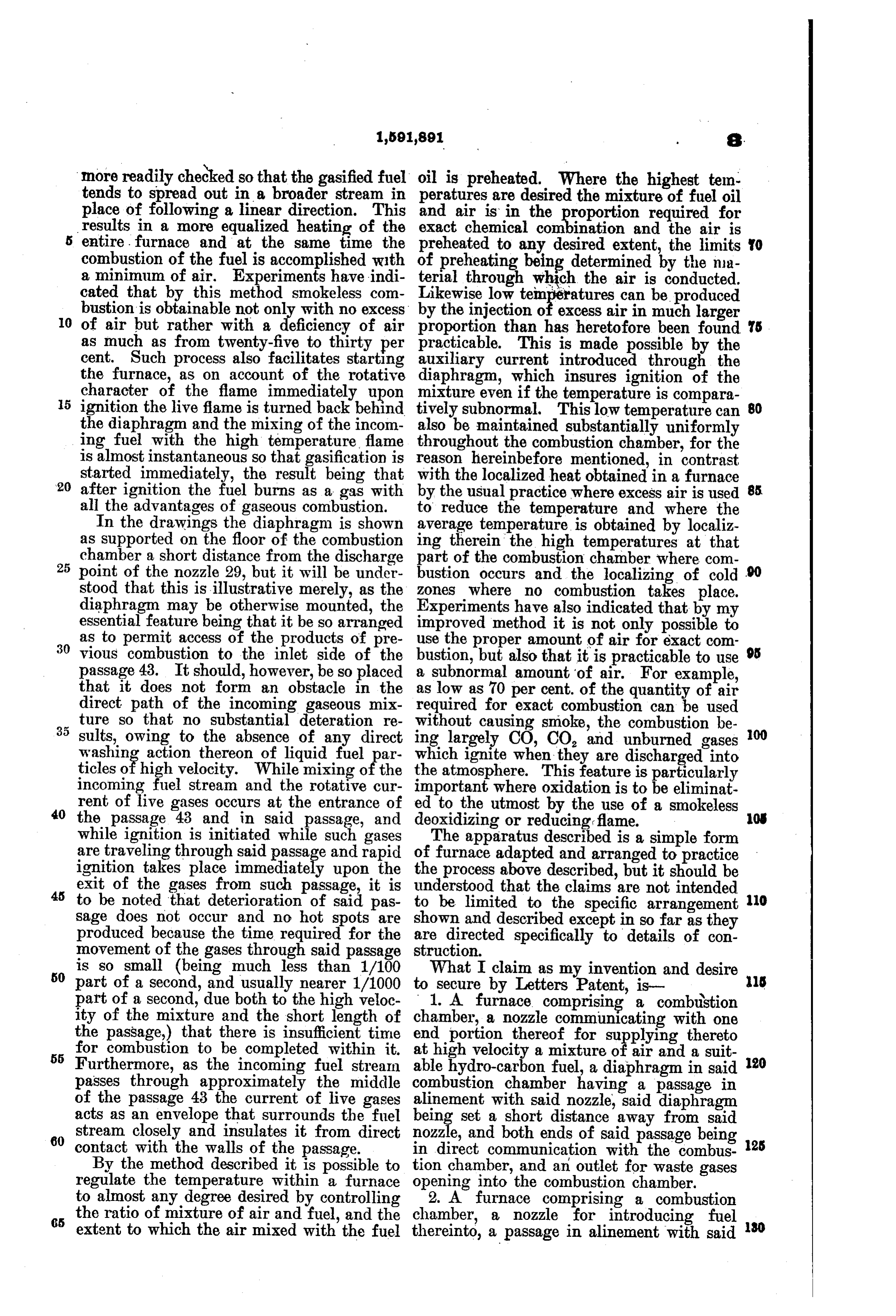
more readily checked so that the gasified fuel oil is preheated. Where the highest tem. tends to spread out in a broader stream in peratures are desired the mixture of fuel oil place of following a linear direction. This and air is in the EE required for results in a more equalized heating of the exact chemical combination and the air is entire. furnace and at the same time the preheated to any desired extent, the limits O combustion of the fuel is accomplished with preheating being determined by the nia a minimum of air. Experiments have indi of terial through which the air is conducted cated that by this method smokeless com Likewise low temperatures can be produced bustion is obtainable not only with no excess by the injection of excess air in much larger 10 of air but rather with a deficiency of air proportion than has heretofore been found s as much as from twenty-five to thirty per practicable. This is made possible by the cent. Such process also facilitates starting auxiliary current introduced through the the furnace, as on account of the rotative diaphragm, which insures ignition of the character of the flame immediately upon mixture even if the temperature is compara 80 5 ignition the live flame is turned back behind tively subnormal. This low temperature can the diaphragm and the mixing of the incom also be maintained substantially uniformly ing fuel with the high temperature, flame throughout the combustion chamber, for the is almost instantaneous so that gasification is reason hereinbefore mentioned, in contrast started immediately, the result being that with the localized heat obtained in a furnace 20 after ignition the fuel burns as a gas with by the usual practice where excess air is used 85.
all the advantages of gaseous combustion. to reduce the temperature and where the In the drawings the diaphragm is shown average temperature is obtained by localiz as supported on the floor of the combustion ing therein the high temperatures at that
chamber a short distance from the discharge part of the combustion chamber where com point of the nozzle 29, but it will be under bustion occurs and the localizing of cold stood that this is illustrative merely, as the zones where no combustion takes place. diaphragm may be otherwise mounted, the Experiments have also indicated that by my essential feature being that it be so arranged improved method it is not only possible to as to permit access of the products of pre 30 vious combustion to the inlet side of the use the proper amount of air for exact com 95 bustion, but also that it is practicable to use passage 43. It should, however, be so placed a subnormal amount of air. For example, that it does not form an obstacle in the as low as 70 per cent. of the quantity of air direct path of the incoming gaseous mix required for exact combustion can be used ture so that no substantial deteration re without causing smoke, the combustion be sults, owing to the absence of any direct ing largely CO, CO, and unburned gases 00 washing action thereon of liquid fuel par which ignite when they are discharged into ticles of high velocity. While mixing of the the atmosphere. This feature is particularly incoming fuel stream and the rotative cur important where oxidation is to be eliminat rent of live gases occurs at the entrance of to the utmost by the use of a smokeless 40 the passage 43 and in said passage, and ed deoxidizing or reducing flame. O while ignition is initiated while such gases The apparatus described is a simple form are traveling through said passage and rapid of furnace adapted and arranged to practice ignition takes place immediately upon the the process above described, but it should be
exit of the gases from such passage, it is understood that the claims are not intended to be noted that deterioration of said pas to be limited to the specific arrangement O sage does not occur and no hot spots are shown and described except in so far as they produced because the time required for the are directed specifically to details of con movement of the gases through said passage struction.
50 is so small (being much less than 1/100 What I claim as my invention and desire part of a second, and usually nearer 1/1000 to secure by Letters Patent, is ls part of a second, due both to the high veloc 1. A furnace comprising a combustion ity of the mixture and the short length of chamber, a nozzle communicating with one the passage,) that there is insufficient time end portion thereof for supplying thereto 55 for combustion to be completed within it. at high velocity a mixture of air and a suit 20 Furthermore, as the incoming fuel stream able hydro-carbon fuel, a diaphragm in said passes through approximately the middle combustion chamber having a passage in of the passage 43 the current of live gases alinement with said nozzle, said diaphragm acts as an envelope that surrounds the fuel being set a short distance away from said 60 stream closely and insulates it from direct nozzle, and both ends of said passage being 25 contact with the walls of the passage. in direct communication with the combus By the method described it is possible to tion chamber, and an outlet for waste gases regulate the temperature within a furnace opening into the combustion chamber. to almost any degree desired by controlling 2. A furnace comprising a combustion 85 the ratio of mixture of air and fuel, and the chamber, a nozzle for introducing fuel 30 extent to which the air mixed with the fuel thereinto, a passage in alinement with said
Page 7
nozzle, the inlet and outlet ends of said pas in a plane which intersects said passages, sage being open to the combustion chamber, forming Earl ducts in said member at an outlet for waste gases opening into the opposite sides of said partition extending 25 combustion chamber. and means over said around said passages, a duct at one end por outlet for heating the air supplied to the tion of said member connecting said sepa combustion chamber. rate ducts together, and connections at the 3. An air heating device for furnaces opposite end portion of said member com comprising a unitary box-like member hav municating respectively with said separate 30 ing a plurality of air passages extending in ducts.
O one direction therethrough, a partition in a 5. An air heating device for furnaces plane which intersects said passages, form comprising a box-like member having a plu ing separate ducts in said member atop rality of air passages extending in one direc posite sides of said partition extending tion therethrough, a partition in a plane around said passages, a duct at one end por 15 tion of said member connecting said separate which intersects said passages, forming sep arate ducts in said member at opposite sides ducts together, and connections at the op of said partition extending around said pas posite end portion of said member communi sages, a duct at one end portion of said mem cating respectively with said separate ducts ber connecting said separate ducts together, 4. An air heating device for furnaces com 20 prising an integral box-like member having and alined connections at the opposite end portion of said member communicating re a plurality of air passages extending in one spectively with said separate ducts. direction therethrough, an integral partition MAX SKLOWSKY.
Provenance
- Collection
- Cited prior art
- Original PDF
- patentimages.storage.googleapis.com →
- Filed
- 1920-03-19
- Pages
- 7
- Method
- pdftotext (the PDF's own text layer) + pdftoppm 300dpi page scans
- Source
- Google Patents bibliographic record
- Granted
- 1926-07-06
- Inventors
- Sklovsky Max; Deere and Co
- Transcribed from
- patentimages.storage.googleapis.com →