patent · US2433618
Fluid fuel internal-combustion air heater
30 December 1947
Page 1
Drawing sheet — no readable text.
Page 2
Drawing sheet — no readable text.
Page 3
Patented Dec. 30, 1947 2,433,618
UNITED STATES PATENT OFFICE
* FLUHD FUELINTERNAL-COMBUSTION
AR HEATER,
: Henry J. De N. McColum; Chicago, Il. Thelma
McColum, executrix of said:Henry J. De N. Mc . . Count deceased assignor to: Stewart-Warrier 4 - Corporation, Chicago, Ill., iš 4 a corporation of - Virginia
Application February 25, 1943, Serial No. 47,080
My invention pertains to heaters: and more -ber particularly to heaters of the internal combustion
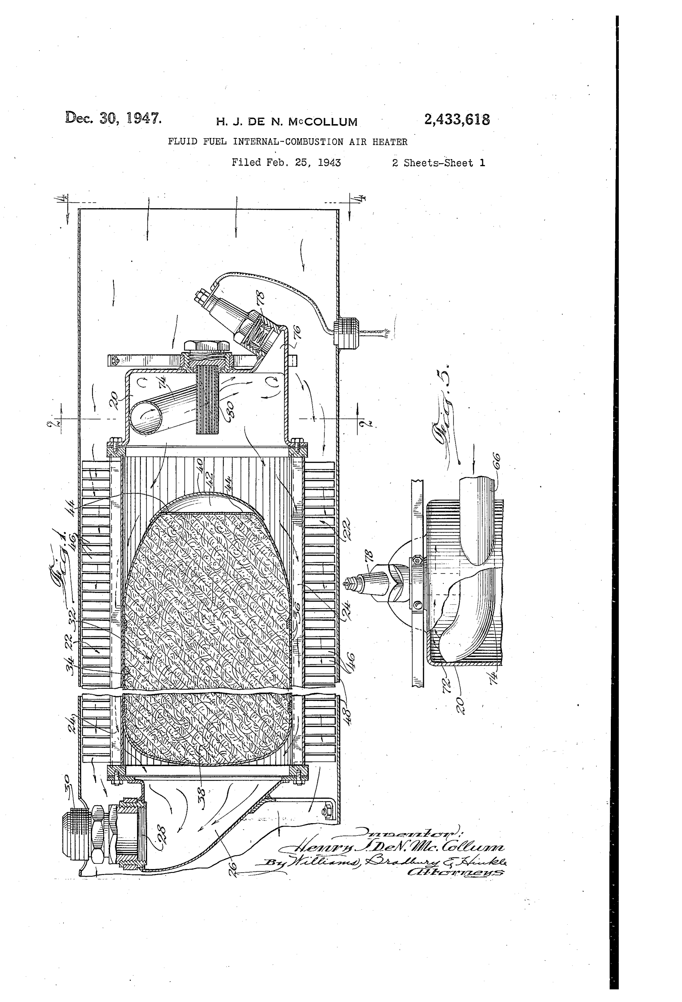
changer. 22. is of tubular shape and has longi type. studinally extending flues 24 through which the An- object of my inveilltioihišº: tÓ. provide an: in hot gases from the combustion chamber pass on ternal combustion type of heater so constructed 55 their way to an outlet chamber 26. The outlet . . that the combustion of the combusible inixture-in . chamber 26 communicates with atmosphere the combustion chanaber cannot 'flashback into through an outlet fitting 28 and any suitable ex the induction tube through which this mixture is haust pipes attached to the threaded end 30 of . Supplied to the cornbustion; chamber. is this fitting.
Another object of my invention is to provide a:0 . A muffler 32- is located in the tubular heat ex heater. of the internal combustion type wherein changer, 22 and comprises a sheet metal shell 35 the combustion tube leading to the combustion having: narrow slots 36 forming acoustic cou chamber is so constructed that it: provides a plings between the flues 24 and the interior of ... Smooth, rapidfow of combustible mixture to the the muffler shell a whereby. Sound may paSS into combustion chamber, this flow being free from.15 this shell and be absorbed by the sound absorbing eddy currents and dead pockets and being at a materia:38, contained therein. This sound ab - rate greater than the rate."offlame propagation sorbing material may be stainless steel wool or whereby combustion in the induction tube is pre- glass wool, or any other suitable Sound absorbing Vented. material. The muffler 32 is provided with a nose & Another object of my invention is to provide!, a .320 4 which aids in directing the hot products of heater of the internal combustion type wherein combustion into the flues 24 and an empty the combustible mixture is delivered to the con- acoustic chamber 42 is formed in this nose and bustion chamber -in such manner as to form a communicates with the interior of the main por. continuous ring of flame, thereby permitting.com- ition of the muffler by way of openings 44. plete combustion of the fuel mixture in: a short, 25 . As the hot gases from the combustion chamber compact combustion" chainber. travellengthwise of the flueS 24, these gases give Another object of my in Wention: iš to provide, a * Up "heat. to the: heat eXchanger 22. . This heat eX heater of the internal combustion type which will changer has fins 46 projecting into the stream of provide any desired. degree of 'preheating of the Ventilating air. Which is directed over the fins combustible mixture and which is equally adapt- 80 by a casing 48 surrounding the combustion cham ed for use with light, and heavy fuel. ber 20 and heat exchanger 22. As this ventilating Another object of 'my invention is to provide , air passes over the fins 46, it is heated and the a heater of the internal combustion:type which heated air...passes from the lefthand end of the is light in Weight, efficient, compact, inexpensive casing:48 into a Space to be heated or into a duct to manufacture, reliable, and capable of giving 35 System having Selected outlets in. Such space or long and trouble-free Service. Spaces. ?
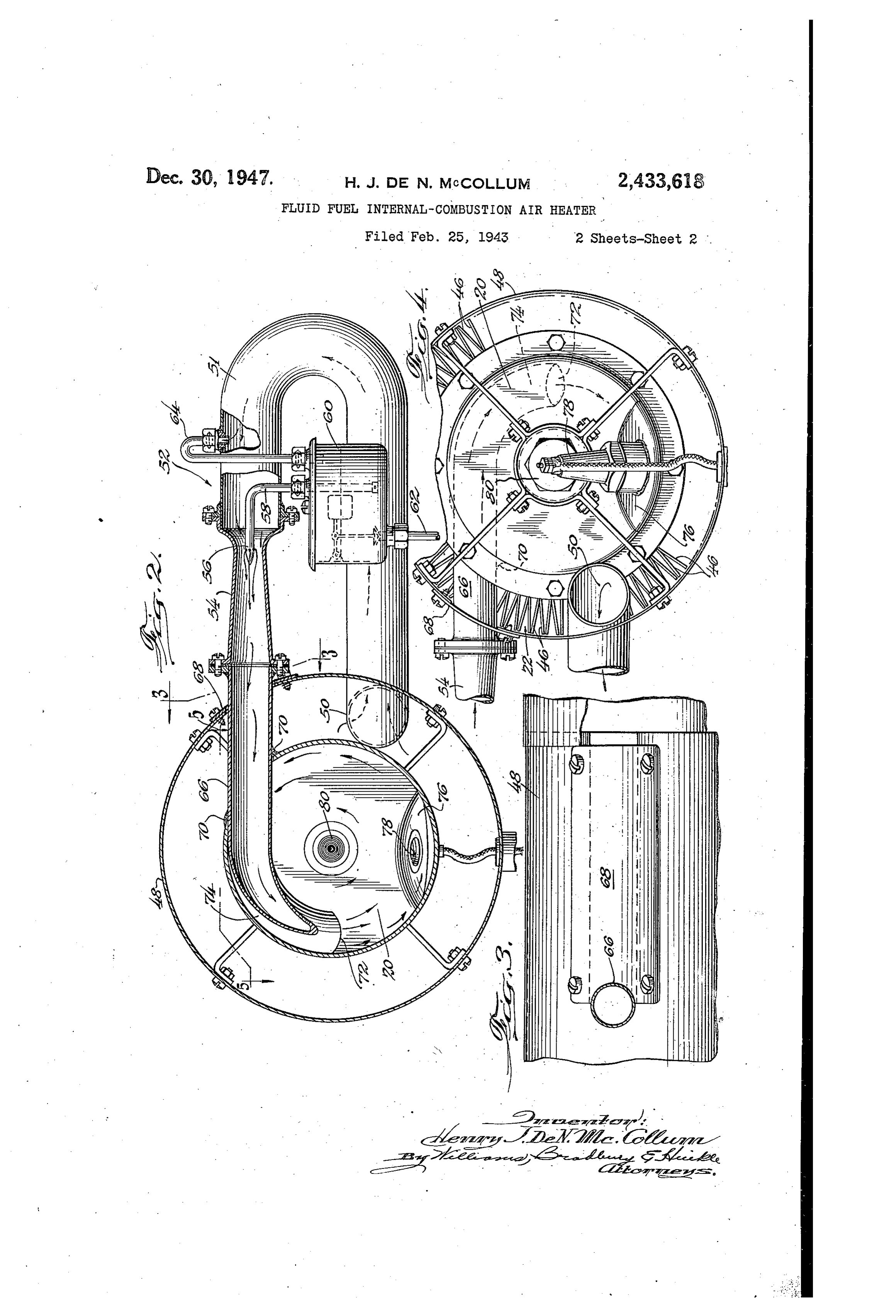
Other objects and advantages will become ap- Air for ventilating purposes and for supporting parent as the description proceeds. . combustion in the combustion chamber 20 is sup In the drawings: '. . plied to a righthand end of the casing 48 by a Fig. 1. is i a longitudinal,: sectional? View of: a, - 40: Iram, blower, or any other suitable means. Most heater enbodying. One form of my invention; Of this air paSSes over the finned heat exchanger Fig. 2 is a transverse, 'Sectional view, taken on 22:... and provides heated ventilating air for the the line 2-2 of Fig. 1; Space or Spaces to be heated. Part of the air sup Fig. 3 is a partial; sectional view taken on the plied to the casing 48, however, enters the inlet irregular line 3-3 of Fig. 2; 4 end 50 (Figs. 2 and 4) of a pipe 5 leading to a Fig. 4 is an end View of the heater shown in carburetor'indicated generally by reference char Fig. 1 looking in the direction of the arrows 4-8 acter 52. This carburetor is provided with the of Fig. 1; and 2 usual Venturi tube 54 having a restricted throat Fig. 5 is a partial, Sectional view taken on the in which the fuel, jet 56 is located. This fuel jet irregular line. 5-5-of-Fig. 2; 60 has a pipe 58 which extends down into and near ihe heater shown in Figs. 1: to 5, inclusive has the bottom of... a conventional float bowl 60. A a Combustion chamber 2, attached to one end of pipe 62 connects the float bowl with any suitable a heat eXchanger 22, which is illustrated as being SOUrce of fuel.
of the type, disclosed and claimed in: ny, co-pend The upper part of the float bowl is connected ing application; »Šerial No. 464,451, filed Novem- *55 by pipe 64 With the pipe 5 f. so that the pressure
Page 4
differential between the pipe 5 and throat of the erating temperature and where this is done it is Wenturi tube is available to lift fuel from the common to use a re-igniter to maintain combus float bowl 60 to the jet 56 and discharge it tion thereafter. I have indicated such a re-igniter through the openings in this jet into the air flow by reference character 8, although in heaters ing through the throat of the Wenturi tube 54. embodying my invention such a re-igniter is not The mixture of fuel and air formed in the Wen essential since the ring of flame in the combus turi tube 54 is delivered to the induction tube 65 tion chamber is sufficient in and of itself to main which passes through the casing 48 and into the tain combustion after the electrical igniter 78 combustion chamber 28. A plate 68 is removably has cut out. This ring of flame starts a short attached to the casing 48, partially to cover an O distance beyond the end 80 of the induction tube opening in this casing which permits insertion and continues around the inner surface of the and removal of the induction tube 66. Where this annular Wall of the combustion Chamber and Over tube passes through a wall of the combustion laps this end 8 to form an unbroken ring of fire chamber 2, the tube is preferably Welded or which ignites the mixture flowing from the end soldered to the combustion chamber wall, as in of the induction tube.
dicated at , to form a gas-tight joint there The whirling motion of the mixture entering between. the combustion chamber and the inclination of The induction tube 66 has a Smooth interior the outer end of the induction tube toward the which is free from obstructions or pockets and rear Wall of this chamber insure complete com which permits a smooth flow of the combustible 20 bustion of the mixture within a very short com mixture therethrough. This induction tube is bustion chamber. This short combustion cham of Such diameter that the rate of flow of the ber reduces the total length of the heater and combustible mixture therethrough is faster than also reduces the weight of the heater. Since the the rate of flame propagation so that in normal Walls of the combustion chamber are directly ex operation of the heater no combustion takes place 25 posed to the ventilating air, all heat which passes in the induction tube. If, for any reason, the into these walls is transferred to the wentilating rate of flow of combustible mixture in the in air and is thus efficiently used and does not rep duction tube should be reduced temporarily so resent a loss.
that Combustion. Would take place in this tube, The induction tube has a smooth inner surface as SOoin as the normal rate of flow of the com 30 which eliminates eddy currents of Small Velocity bustible mixture is restored, the burning gases which would support combustion in the normal Will be driven from this tube into the combustion operation of the heater. The diameter of the chamber and continuance of combustion in the induction tube is so selected that the rate of flow induction tube will be avoided. The smooth, uni of combustible mixture therethrough is faster for in diameter of this tube is an important factor 35 than the rate of flame propagation, so that no in this regard, since it prevents the formation of combustion takes place in this tube during nor eddy currents or pockets where combustion could mal heater operation. If, for any reason, the continue bacause the rate of flow in these eddy rate of flow of the combustible mixture in the currents would be less than the rate of flame induction tube should be temporarily reduced suf propagation. 40 ficiently to permit combustion to take place in In the normal operation of the heater, the com this tube, all burning gases will be immediately bustible mixture does not burn until after it has discharged from the induction tube as Soon aS moved an appreciable distance beyond the dis normal flow of combustible mixture is restored. charge end 12 of the induction tube. The part That part of the induction tube lying within i4 of this induction tube which lies within the the combustion chamber may be made of any combustion chamber 2 forms a means for pre length to give the desired preheating and is pref heating the mixture of fuel and air to any de erably of such length that the mixture entering sired degree before this mixture is ignited. In the combustion chamber is preheated to such a Fig. 2, the preheating portion 4 of the induction degree that it will burn cleanly and quickly as tube is shown as extending through an arc of 5 soon as it is ignited. This feature, together with somewhat more than 90° which affords ample the circular motion of the combustible mixture preheating where the heater is operated with in the combustion chamber and the resultant ring gasoline or other relatively light fuels. of flame, permit complete and efficient combus Because of the curvature of the portion it of tion in a combustion chamber of short length the induction tube, the mixture delivered to the and without increasing the diameter of the con combustion chamber whirls about the longitudi bustion chamber over that commonly used in such nal axis of this chamber, as clearly indicated by heatel'S.
the arrows in Fig. 2. The curved portion A of Because of the provisions for obtaining any de the induction tube, however, does not necessarily sired amount of preheating of the combustible lie in a plane perpendicular to the axis of the 60 mixture, my novel heater is equally adapted for combustion chamber and in the particular em use with kerosene, fuel oils and other relatively bodiment shown the end portion of this tube is heavy fuels, as well as gasoline and other light inclined, as shown in Fig. 1, to direct the con fuels.
bustible mixture toward a pocket 76 formed at It is to be understood that my invention is not one end of the combustion chamber. The electri limited to the details shown and described, but cal igniter 78 communicates directly With this may assume numerous other forms and that the pocket which receives fresh combustible mixture scope of my invention is defined in the following from the induction tube, but slows down the rate Clain.
of travel of this mixture to such an extent that I claim:
it may be easily ignited. 70 A heater Of the class described having heat ex The electrical igniter 79 may operate continu change means, comprising means forming a conn ously. However, in heaters of this type it is usual bustion chamber, means connecting said con to connect this igniter with its source of current bustion chamber With said heat exchange means through a thermostatic switch which cuts out the for the delivery of hot gases thereto, means in signiter after the heater has attained normal op 75 cluding an induction tube of substantially uniform
Page 5
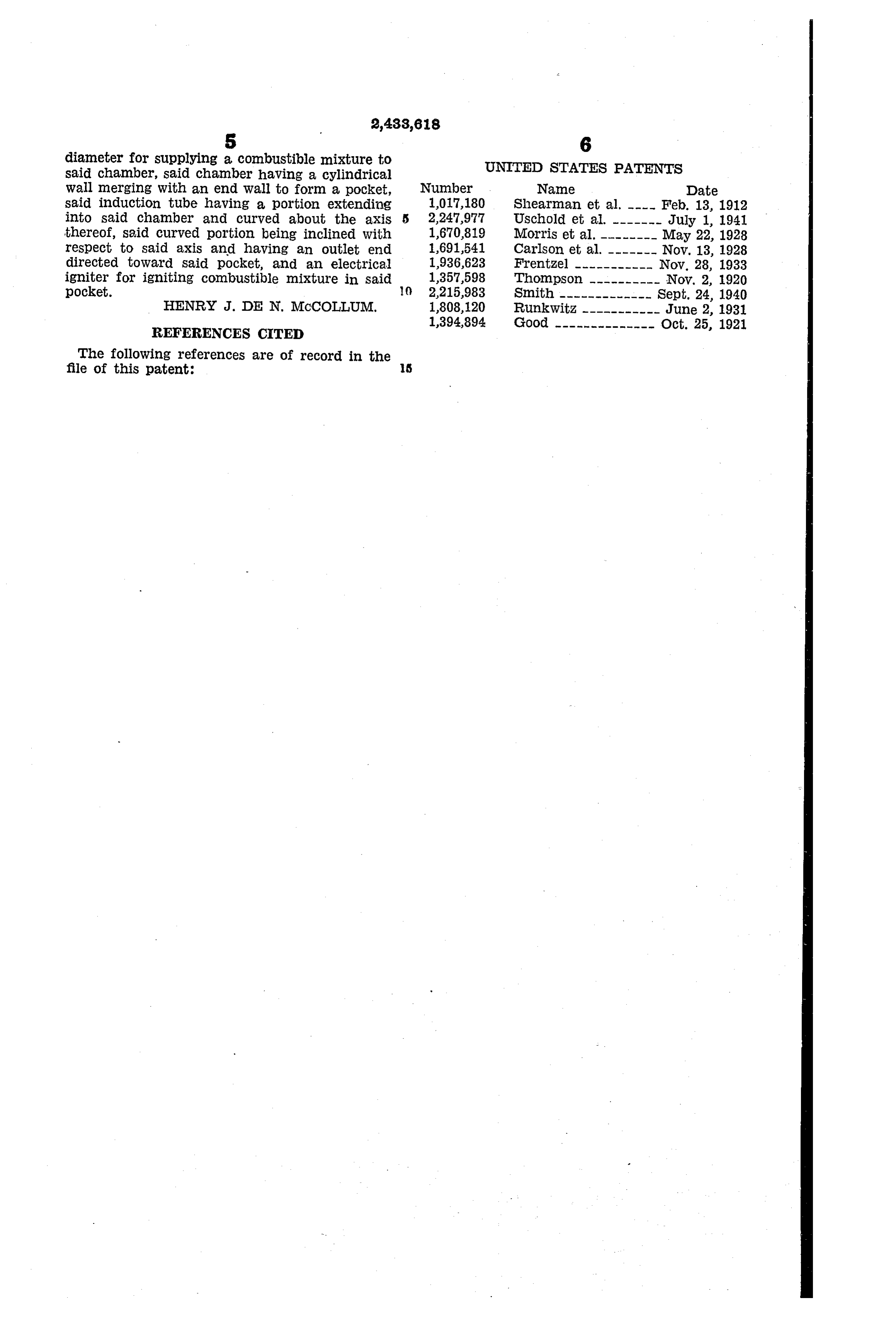
diameter for supplying a combustible mixture to UNITED STATES PATENTS said chamber, said chamber having a cylindrical wall merging with an end wall to form a pocket, Number Name Date said induction tube having a portion extending 1,017,180 Shearman et al. ---- Feb. 13, 1912 into said chamber and curved about the axis 5 2,247,977 USchOld et all. -------- July 1, 1941 thereof, said curved portion being inclined with 1,670,819 Morris et al. -------- May 22, 1928 respect to said axis and having an outlet end 1,691,541. Carlson et al. ------- Nov. 13, 1928 directed toward said pocket, and an electrical 1936,623 Frentzel ----------- Nov. 28, 1933 igniter for igniting combustible mixture in said 1,357,598 Thompson ---------- Nov. 2, 1920 pocket. () 2,215,983 Smith ------------- Sept. 24, 1940 HENRY J. DE N. MCCOLLUM. 1808,120 RunkWitz, ----------- June 2, 1931
REFERENCES CITED
The following references are of record in the
Provenance
- Collection
- Cited prior art
- Original PDF
- patentimages.storage.googleapis.com →
- Filed
- 1943-02-25
- Pages
- 5
- Method
- pdftotext (the PDF's own text layer) + pdftoppm 300dpi page scans
- Source
- Google Patents bibliographic record
- Granted
- 1947-12-30
- Inventors
- Mccollum Thelma; Stewart Warner Corp
- Transcribed from
- patentimages.storage.googleapis.com →