patent · US2362972
Gas burner
21 November 1944
Page 1
Drawing sheet — no readable text.
Page 2
Drawing sheet — no readable text.
Page 3
Patented Nov. 21, 1944 2,362.972
UNITED STATES2,362,972PATENT OFFICE
GAS BURNER.
Henry Lowe Brownback, Norristown, Pa. -
Application December 26, 1939, Serial No. 310,995
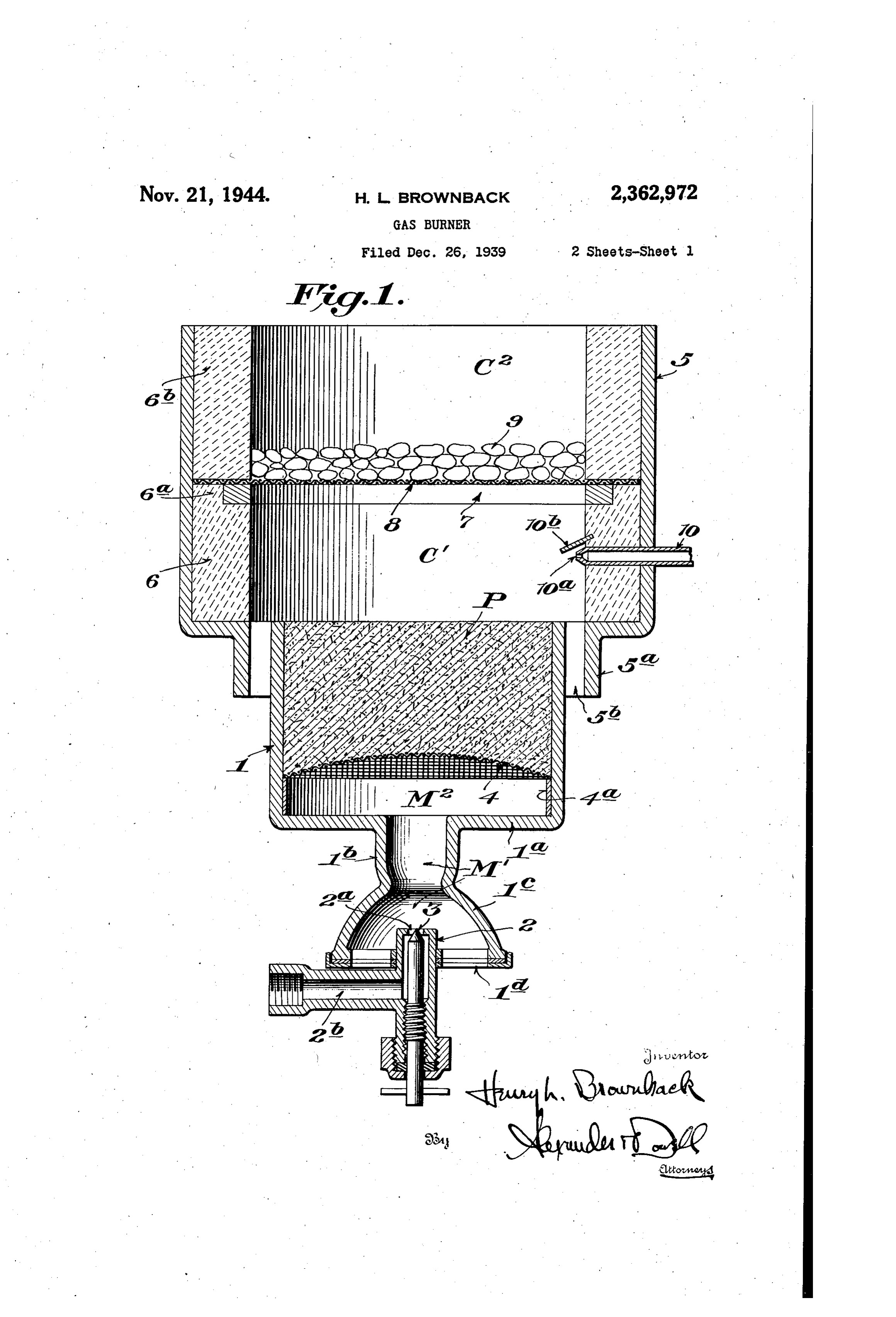
This invention is a novel improvement in gas cup-shaped casing , open at the top and having burners, particularly adapted for use in cooking a botton plate a provided with a contracted ex and heating Stoves and in boilers. tension b, the lower end of which is provided The Ordinary gas burner in present use con with a downwardly flaring hood ?c, the parts b sists of a multiple orifice Bunsen-type burner in and c forming the primary gas and air mixing which a mixture of gas and air is burned in the chamber M' of the burner. Extending upwardly atmosphere. This type of burner usually gives into hood ?c is a gas nozzle 2 having an orifice 2a. off considerable Odor, and often produces carbon governed by a manually adjustable valve 3 to monoxide gas, also the flame may be easily control the amount of gas entering from the gas extinguished by overflowing liquids from pots or O pipe 2b into the primary mixing chamber M'. kettles, or by air currents if the gas is turned low, Air enters the primary mixing chamber M' at and such burners cannot be used for broiling in the lower open end of hood ic exteriorly of the the usual manner of placing the food to be broiled nozzle 2, and preferably air regulating means is above the burner. Furthermore the heating sur provided consisting of a pair of relatively adjust face of Such burners is not uniform, but is local 5 able superimposed perforated plates d at the ized along the axes of the Series of burner orifices. lower end of the hood c. If desired an air The principal objects of my invention are to blower 6r other means for supplying forced draft provide an improved 'sub surface' combustion of air into the primary mixing chamber M may type burner designed to eliminate all of the above be provided.
mentioned disadvantages and to provide a burner . 20 Within the casing f and spaced from the lower which will present an even fire resembling in heat end thereof is a screen or grating 4 preferably distribution and appearance a fine charcoal fire, extending across the casing and Supported on an above which food can be broiled without absorb annular frame 4a fitted within the Walls of the ing any "gas' taste; also to provide a burner in . . casing. The chamber below the screen or grat which the gas is burned into carbon dioxide by 25 ing 4 may be empty to provide a secondary mix reason of multiple combustion steps, thus pro ing chamber M2 for the gas and air; or if desired ducing maximum heat from a given quantity of said space below screen 4 may be filled with gas; also to provide a burner which will be less tinsel or the like to assist in mixing the gas and subject to maladjustment than the ordinary air therein. Above the screen or grate 4, the burner, and in which provision is made to render 30 casing f is packed with non-combustible porous same Safe against overflowing pots and kettles; packing material P (in Fig. 1) such as asbestos, also to provide a burner in which there are no rock wool, spun glass, or the like, forming a gas Small burner Orifices exposed to dirt, grease and distributor and backfire trap. The upper face of corrosion as in the ordinary type burner, and packing P forms the bottom of the primary com hence to provide a burner in which there is no 35 bustion chamber C", which chamber is formed in danger of clogging or choking the jet orifices. a casting 5 having a contracted lower end 5a into I will explain the invention with reference to which the upper end of casing enters, leaving a the accompanying drawings, which illustrate Sev space 5th between the parts 5a and through eral practical embodiments thereof to enable which the secondary air for the primary combus others familiar with the art to adopt and use the 40 tion chamber C" enters.
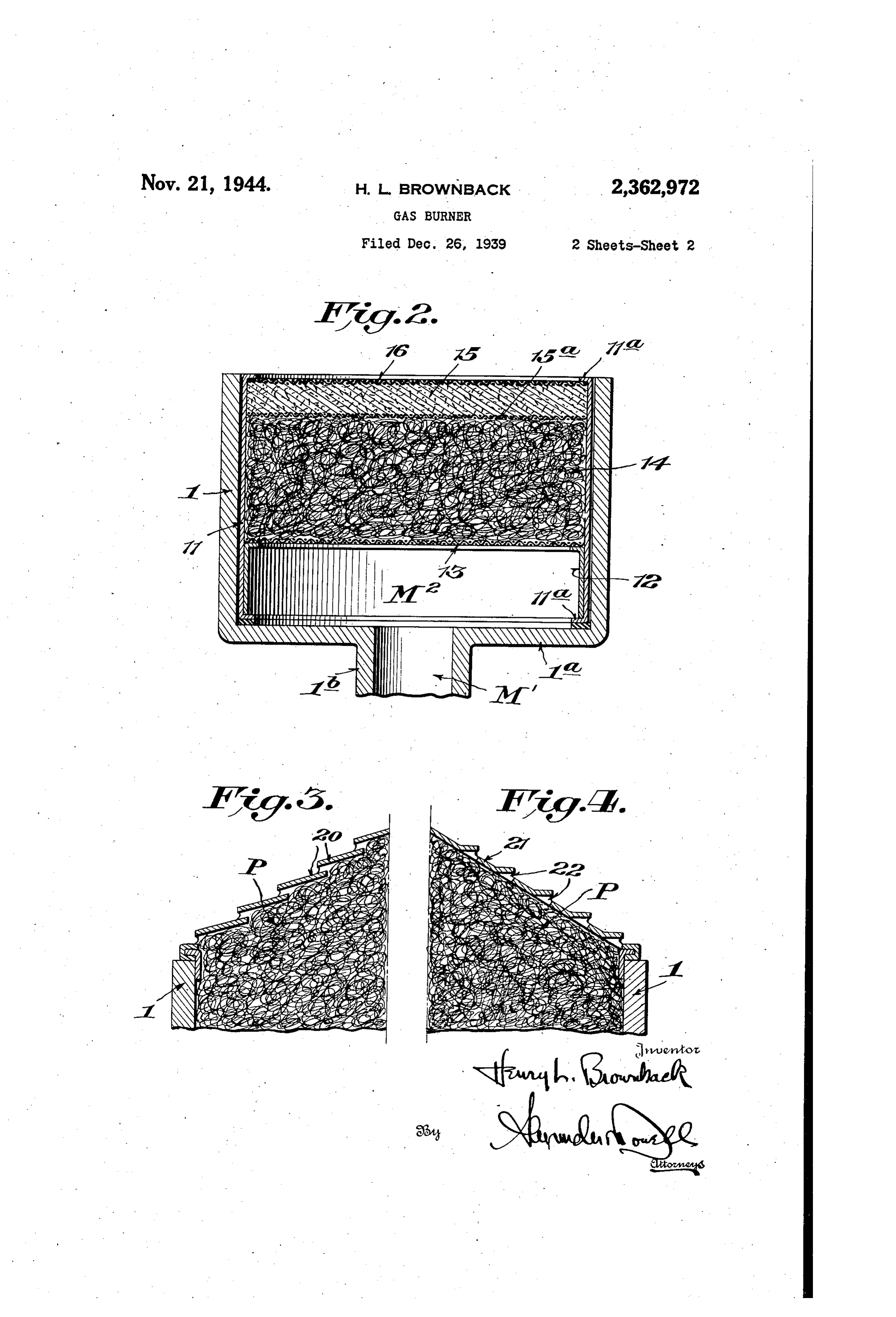
same; and will summarize in the claims the novel Within the lower portion of casing 5 is a refrac features of construction, and novel combinations tory lining 6 of substantial thickness to protect of parts, for which protection is desired. . . the walls of the casing and to prevent loSS of heat In said drawings: . is therethrough. Lining 5 extends substantially Fig. 1 is a vertical Section through One form of 45 half the height of casing 5: Seated in an annu my novel gas burner. Fig. 2 is a vertical section lar recess at the top of the lining 6 is a grate showing a modification utilizing a pre-formed above which is disposed a screen 8. Above Screen filter cartridge unit in the Secondary mixing 8 is a refractory lining Stb extending to the top of chamber of the burner. Fig. 3 is a vertical sec 50. the casing 5. Upon screen 8 is a layer, 9 of car tion through a further modification showing one borundum, or surface combustion aggregates, Or form of cover used on the secondary mixing other like refractory material, said layer 9 being chamber. Fig. 4 is a vertical section showing of substantial thickness and preferably though another form of cover for the Secondary mixing not necessarily terminating below the top of cas chamber. ing 5. The portion of the casing 5 above the My novel gas burner preferably comprises a 55 layer 9 forms the Secondary Combustion cham
Page 4
ber C2. The bed of aggregates above the screen cool the latter and pass down through on the 8 in the chamber 5 provides for secondary com burner, such liquid would run down the conical bustion and heat distribution, the aggregates be COWers and pass Out of the secondary air inlets coming incandescent by action of the combustion 5b without extinguishing the burner. Preferably in the primary combustion chamber C', and the is the cover is provided with a flange adapted to fit Secondary combustion in the layer 9 maintains a Within the upper end of the casing . When a glowing bed of aggregates in chamber 5 giving a cover is used the porous filling material P in the radiant heat with practically no flame. Casing would preferably extend up to the under For the purpose of igniting the air and gas side thereof, and the porous insulating material mixture in the primary combustion chamber C, 10 P Would distribute the gas-air mixture evenly to I provide a pilot consisting of a gas tube to enter the underside of the protective cover and the ing the side of casing 5 and extending through mixture would pass through the slots, or louvres lining 6, Said tube having a jet orifice Oa at its and burn.
inner end for the pilot flame which may be left The operation of the burner as described is as burning at all times. The pilot flame provides 15 follows: In my novel burner the gas and air is fed double Safety as any possible escape of gas due to into a primary mixing chamber M' in the usual a partially closed cock in gas pipe 2b would not typemanner either by the injector action of a Bunsen paSS directly into the air as in the ordinary burner mixer, or by a forced draft blower type but would collect in the primary combustion mixer, and the gas-air mixture is carried to the chamber C and would there be ignited by the 20 secondary mixing chamber M2 which is open at pilot light 0a; and since the pilot Oa is disposed the top and may be empty or filled with tinsel or in the enclosed combustion chamber C’ there like material through which the mixture can cir would be little likelihood of the pilot flame being culate freely. The gas-air mixture then passes extinguished by a sudden gust of wind. Above upwardly through grid or screen 4 or 3 into a bed of porous insulation P or 4-5 in the cas the pilot orifice Oa is a deflector plate fob for 25 ing the purpose of preventing any liquids which which distributes the gas-air mixture even might drip down into the primary combustion ly at the upper surface thereof, at which point the chamber C from extinguishing the pilot flame. gas-air mixture is burned, the porous insulation . Instead of using the filling P in the casing P or 4-5 serving as a backfire trap to keep the as shown in Fig. 1, the filling can be made up as 30 heat of the flame from igniting the gas in the mixing chambers M', M2. The upper end of the a cartridge shown in Fig. 2, similarly to the oil filter cartridges used in motor cars, and this car porous insulation P or 4-5 forms the bottom of the insulated primary combustion chamber C', tridge replaced periodically if found necessary or in which chamber additional air from ducts 5b desirable. The pre-formed burner cartridge as 35 is fed to the burning gas-air mixture. This addi ShoWn consists of a metallic shell if of diame tional air mixes with the original products of ter and size to suit the internal dimensions of combustion, the casing , said shell preferably having internal through grateand passes with them upwardly 7 upon which is placed the layer annular flanges fia at its ends. Within the shell f is a shell 2 of less height seated upon the 9 of carborundum, aggregates or Similar non lower flange fa, and upon the top of shell 40 combustible material which is heated by the 2 is a screen or grid 3 forming the top of the products of Combustion to a high degree. The layer 9 of combustible material serves the
Secondary mixing chamber M2. Above the screen or grid 3 is a packing of porous insulating ma purpose of providing a fine, even, odorless, flame less or almost flameless heat, and the excess air terial Such as rock wool, asbestos, spun glass, or 45 and the like, and upon the top thereof is a screen or products of combustion containing carbon grid 5d upon which is a layer of asbestos fibre or passing through the heated layer are combined the like 5 covered by a screen f6 engaging the to burn any residual carbon monoxide into car upper flange fla of the shell f. The above con bon dioxide, thus obtaining more heat from the Struction forms a unit which may be inserted as fuel and eliminating carbon monoxide which is a cartridge into the casing , which unit is inex 50 an active poison. This heat given off by the pensive to manufacture and is readily removable heated bed of non-combustible material is ideal from and replaceable in the casing. The cartridge for all kinds of heating and cooking, including shown in Fig. 2 also provides an efficient backfire broiling, as the meat or fish to be broiled is heated trap, and the gases passing up through the porous evenly while no odor of unburned products of layers 4 and 5 are spread evenly throughout 55 the primary combustion can be absorbed therein the mass So that the flame at the top of layer as is the case when using the Ordinary Bunsen 6. Will burn evenly over the entire area of the type burner; also any fat, etc., dripping from the casing which forms the bottom of the primary material being broiled will drop onto the heated Combustion chamber C. layer 9 and will there be burned without reach It may be found desirable to provide covers 30 ing the primary combustion chamber C. upon the casing f such as shown in Figs. 3 and 4, The actual combustion takes place in a Sub as an added Safety measure to protect the car stantially closed compartment (Save for the Sec tridge from any liquids which might boil over ondary air inlets 5b which are protected from and pass down through the combustion chambers drafts) so that there is no danger that sudden C2 and C and which might thus soak the car 65 air currents can extinguish the flame. Any gas tridge or injure same. The cover may consist leakage caused by accidental turning on the gas of an Overlapping series of conical rings 20 with cocks will not result in gas leaking into a room Spacers between adjacent rings as shown in Fig. as any such gas passing must pass into the con 3: Or the cover may consist of a conical plate bustion chamber C' where it will be ignited by 2 having louvres 22 formed therein as shown in 70 the pilot light. Any grease falling on layer 9 dur Fig. 4, or may be otherwise formed to deflect any ing broiling cannot clog the burner, as it will be liquid which might drop through the combustion consumed directly on the heated and glowing chambers from falling on the cartridge. In case layer.
a large volume of liquid was spilled on the heated Thus my burner provides an even, flowing, in layer 9 of non-combustible material sufficient to 75 tense heat, eliminating danger from carbon
Page 5
monoxide, and combustion takes place in an en means for introducing gas and air into said cham closed, insulated chamber which concentrates in ber, Said burner having a secondary mixing stead of wastes heat. The air inlets 5b to the chamber receiving the mixture from the first combustion chamber C provide an additional mixing chamber and having an open end; safety factor in that they prevent building up of 5 non-combustible porous packing in said second excess pressures in the otherwise closed chamber, chamber through which the gas-air mixture dif and these inlets 5b are pointed down away from . fuses; a casing forming an insulated primary any perSOas or any combustible material which combustion chamber into which the open end might be in the path of any gas “flash." of the Secondary mixing chamber projects; means The burner will operate. regardless of the posi O for admitting secondary air into said combustion tion in which it is placed, whether vertical, hori chamber; said casing also forming a secondary Zontal or otherwise, since the porous sections Combustion chamber adjacent said primary com serve to thoroughly distribute the gases passing bustion chamber; and a porous relatively thick through to the primary combustion chamber, layer of non-combustible material separating irrespective of the angularity of the axis of the said primary and secondary combustion chambers burner; and the same flameless refractory bed ap and adapted to be heated to a high degree by the pears at the Surface of the aggregates regardless products. Of combustion. of the position of the burner. 8. In a gas burner as set forth in claim 7, a Burner units as above described may be used preformed unit containing said packing for said in place of the customary burners in any types 20 Secondary mixing chamber; said unit substan of gas cooking or heating stoves or boilers. tially conforming with the size and shape of said I claim: . chamber and filling the upper portion thereof 1. A gas burner having a mixing chamber at and being insertable and removable therefrom one end and having its opposite end open; means . . . through said open end; and said unit comprising for introducing gas and air into said chamber; a shell Open at both ends, a screen extending non-combustible porous packing in the open end across said shell and spaced from one end, a of said burner through which the gas-air mix Second Screen acroSS the other end, and said ture diffuses; an insulated casing forming a pri packing being disposed between said screens. , mary combustion chamber into which the open 9. For a gas burner having a mixing chamber end of the burner projects; means for admitting having side walls and open at its upper end; the Secondary air into the combustion chamber; said 30 lower end being closed-and provided with an in Casing also forming a secondary combustion let for introducing gas and air into said cham chamber adjacent said primary chamber; and a ber; a pre-formed unit confined within said porous relatively thick layer of non-combustible chamber containing non-combustible porous material Separating said primary and secondary packing, and substantially conforming with the combustion chambers and adapted to be heated area and shape of said mixing chamber and filling to a high degree by the products of combustion. the upper portion thereof, said unit being in 2. In a gas burner as set forth in claim 1, a Sertable and removable therefrom through said Open end; a casing forming a primary combus preformed cartridge-like unit containing said packing; said unit Substantially conforming with 40 tion chamber into which the open end of the the size and shape of said burner and filling the mixing chamber projects; a secondary combus upper portion thereof and being insertable and tion chamber adjacent said primary chamber; renovable therefrom through said open end. and a porous relatively thick layer of non-com 3. In a gas burner'as set forth in claim 1, a bustible material separating said primary and preformed cartridge-like unit containing said secondary combustion chambers and adapted to packing insertable and removable therefrom be heated to a high degree by the products of through said open end; Said unit comprising a Combustion, shell conforming with the length and shape of 10. In a gas burner as set forth in claim 9, said said burner and filling the upper portion thereof unit comprising a shell open at both ends, a and being open at both ends, a screen extending 50 Screen extending across said shell and spaced across said shell and Spaced fron One end, a from one end, a second screen across the other second screen across the other end, and said end, and Said porous packing being disposed be packing-being disposed between said Screens. tween said Screens, 4. In a gas burner as set forth in claim 1, a 11. In a gas burner, a gas-air mixing chamber conical cover over the porous packing, said cover 55 Open at its upper end; said chamber having side having concentric series of stepped portions pro Walls and a bottom wall provided with a gas-air vided with openings between the steps so as to mixture inlet, a non-combustible porous packing divert liquids from passing therethrough While in said chamber above the bottom wall through permitting the gas-air mixture to enter the which the gas-air mixture diffuses; a primary primary combustion chamber therethrough. combustion chamber ha. ving an opening into 5. In a gas burner as set forth in claim 1, a BO which the upper end of the mixing chamber pro cover over the porous packing of Said mixing jects; and a conical cover over the porous pack , chamber adapted to divert liquids therefrom while ing of said mixing chamber, said cover having permitting the gas-air mixture to enter the pri concentric series of stepped portions provided mary combustion chamber; said cover compris with openings between the steps so as to divert ing a superimposed series of conical rings of pro 35 liquids therefrom while permitting, the gas-air gressively decreasing diameters, the overlapping mixture to pass through the porous packing. faces of adjacent disks being spaced apart. 12. In a gas burner as set forth in claim 11, 6. In a gas burner as set forth in claim 1, a said cover comprising a superimposed series of cover over the porous packing of said mixing conical rings of progressively decreasing diam chamber adapted to divert liquids therefrom O eters, the overlapping faces of adjacent disks be-, while permitting the gas-air mixture to enter the ing spaced apart.
primary combustion chamber; said cover com 13. In a gas burner asset forth in claim 11, said prising a conical-shaped cap having series of cover comprising a conical-shaped cap having louvres formed therein. iseries of louvres formed therein, 7. A gas burner having a mixing chamber; 5 14. In a gas burner as set forth in claim 11, a
Page 6
pre-formed unit containing said packing for said from through said open end; said unit com mixing chamber; said unit substantially con prising a shell conforming with the length and forming with the size and shape of said mixing shape of said mixing chamber and being open chamber and filling the upper portion thereof, at both ends, a screen extending acroSS said shell and being insertable and removable therefrom and spaced from one end, a second screen across through said open end. the other end, and said packing being disposed 15. In a gas burner as set forth in claim 11, a between said Screens.
pre-formed unit containing said packing for said mixing chamber, insertable and removable there HENRY LOWEBROWNBACK.
Provenance
- Collection
- Cited prior art
- Original PDF
- patentimages.storage.googleapis.com →
- Filed
- 1939-12-26
- Pages
- 6
- Method
- pdftotext (the PDF's own text layer) + pdftoppm 300dpi page scans
- Source
- Google Patents bibliographic record
- Granted
- 1944-11-21
- Inventors
- Brownback Henry Lowe
- Transcribed from
- patentimages.storage.googleapis.com →