patent · US1614359
Liquid-fuel burner
11 January 1927
Page 1
Drawing sheet — no readable text.
Page 2
Drawing sheet — no readable text.
Page 3
Patented Jan. 11, 1927. 1,614,359
UNITED STATES PATENT OFFICE.
RALPH. M. GASTON, OF CHICAGO, ILLINOIS, ASSIGNOR, BY. MIESNE ASSIGNMENTS, TO WAYNE COMPANY, OF FORT WAYNE, INDIANA, A CORPORATION OF INDIANA,
LIQUID-FUE BURNER.
Application filed October 16, 1922. Serial No. 594,694.
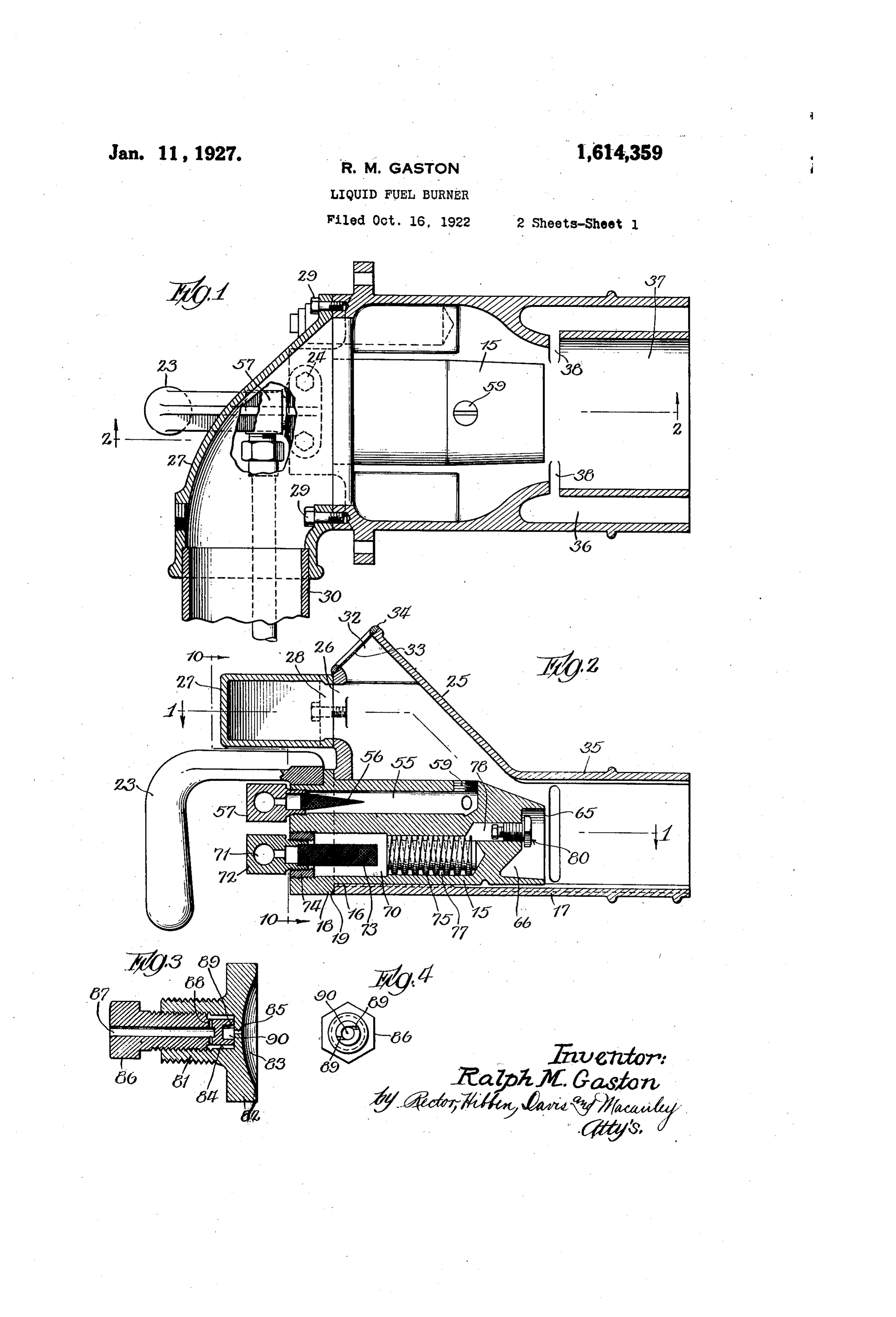
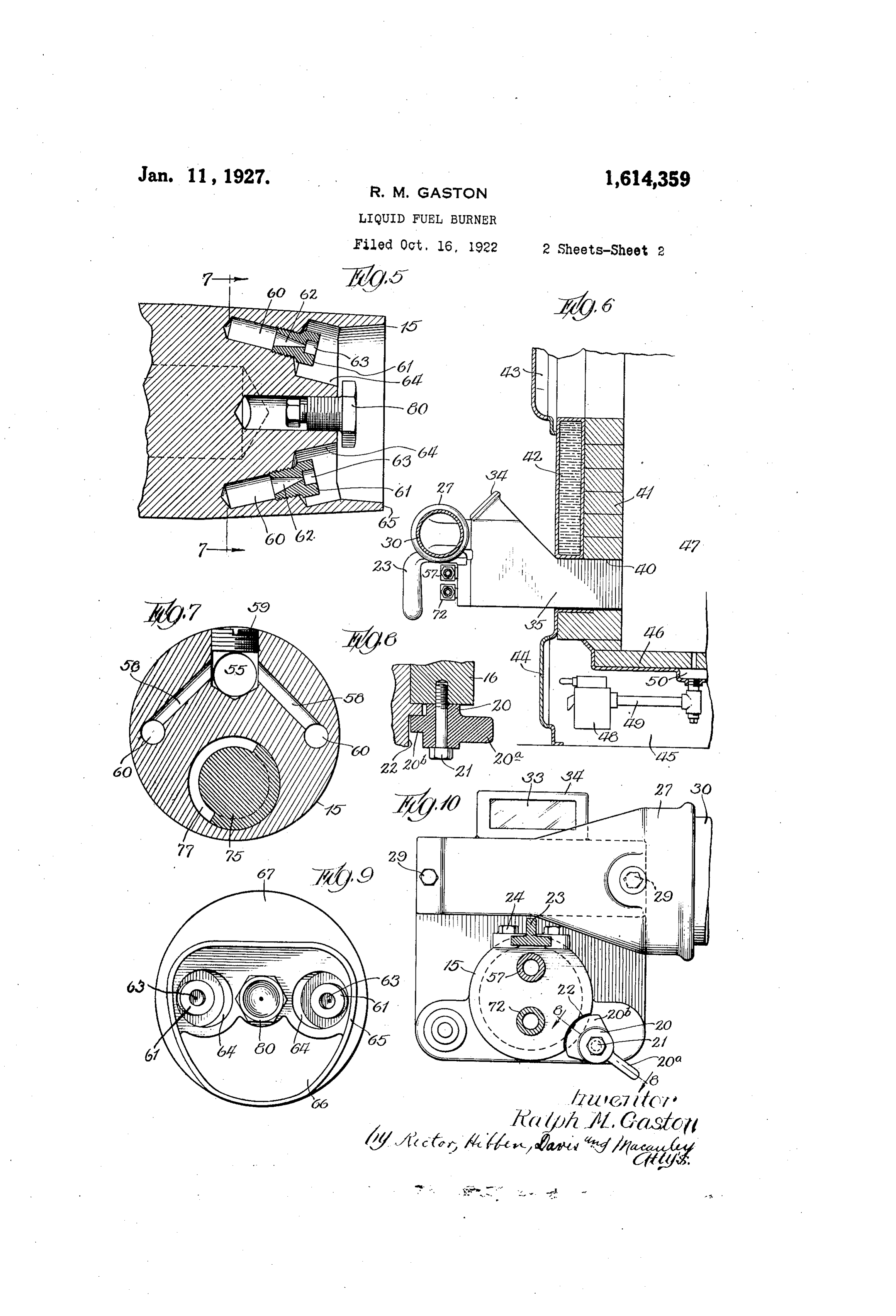
This invention relates to liquid fuel burn is a section taken on the line 10-10 of Fig. ers adapted for use in burning various 2, showing a front elevation of the burner grades of oil in connection with furnaces casing and connected parts.
and the like. The principal object of the tionAs comprises illustrated in the drawings, the inven a substantially cylindrical invention is to provide an improved form of liquid fuel burner adapted for use in con burner member 15 adapted to engage a cir nection with the steam, hot water boilers cular opening 16 formed in the front end or furnaces of the heating systems installed wall of the burner casing 17. The burner in residences and other buildings. An im 15 is provided at its rear end with an an 10 portant feature of the invention is the pro nular projecting shoulder 18 which seats 05 vision of a burner having a spray nozzle against the shoulder 19, formed around the through which the fuel is forced directly opening 16, and the burner is detachably into the furnace, the fuel being pulverized or held in this position by means of a cam 20 distributed in a much larger air volume, which is secured to the burner casing by a 5 thereby securing a more perfect combustion. cap screw 21 and adapted to be operated by 70 The operation of spraying the fuel to form a handle 20 to cause the projecting blade a fine mist adapted to produce a more ef 20 of the cam to engage a curved notch fective combustion is facilitated by the heat 22 which is formed in the outer part of the ing of the fuel before it reaches the spray annular shoulder 18, as shown particularly 20 nozzle, so that ignition of the fuel is readily in Fig. 10. The burner is adapted to be secured by a small gas pilot light or other inserted or withdrawn from the casing 17 equivalent device located adjacent the liquid by means of a handle 23 which extends fuel nozzle. The burner is always ready to downwardly in front of the burner and is begin efficient operation because the preheat secured to the upper part of the annular 25 ing chamber always holds a quantity of shoulder 18 by means of cap screws 24. The 80 liquid fuel sufficient for operation until the burner housing or casing 17 is provided with fire pot of the furnace becomes heated; and an upward extension 25 above the burner this fuel is always kept hot, during the idle 15 and this extension has a rectangular periods of the burner. Other objects of the opening 26 in its front wall adapted to be 30 invention relate to various features of con connected with an elbow 27 having a sim 85 struction and arrangement which will ap ilar rectangular opening 28 to register with pear more fully hereinafter. the opening 26, the elbow being secured to The nature of the invention will be un the front wall of the burner casing by means derstood from the following specification of cap screws 29. The elbow extends in t taken with the accompanying drawings in a lateral direction with respect to the casing 90 which one embodiment is illustrated. In the and is provided at its other end with a cir drawings, Fig.1 shows a substantially hori cular opening adapted to communicate with Zontal section through the burner casing and an air pipe 30 through which air for sup connected parts, the section being taken on porting the combustion of the fuel is sup 40 the line 1-1 of Fig. 2; Fig. 2 shows an plied under pressure by means of a suitable 95 enlarged vertical section through the parts blower, or other air mover. The upward of the burner on the line 2-2 of Fig. 1; extension 25 of the casing is provided im Fig. 3 shows an enlarged longitudinal sec mediately above the elbow 27 with an in spection opening 32 closed by a sheet 33 of 00 tion through the liquid fuel nozzle; Fig. 4 isinglass 45 shows an end elevation of the inner plug held in place by a surrounding re of the fuel nozzle; Fig. 5 shows a section taining member 34. The part 35 of the through the longitudinal center line of the burner casing 17 which projects inwardly burner; Fig. 6 shows a vertical section opposite the mouth of the burner 15 to form through a portion of a furnace illustrating a combustion tube, is provided on opposite 105 5 the location of the liquid fuel burner in con sides with passages 36 which open at the nection therewith; Fig. 7 shows a trans inner end of the casing and which communi verse vertical section on the line 7-7 of cate with the central passage 37 of the cas ing through vertical slots 38 formed in the
Fig. 5; Fig. 8 is a detail section on the line side 8-8 of Fig. 10; Fig. 9 shows an elevation walls of this passage. Heated gases 0 55 of the inner end of the burner; and Fig. 10 from the interior of the furnace are induced
Page 4
to pass through the openings 36 and 38 to the mouth of the burner, by the suction 70provided with another longitudinal passage created by the passage of the mixture serves as a preheatingcylindrical of substantially form which through the combustion tube where they fuel. This fuel is supplied by a pipetheleading chamber for liquid mingle with the liquid fuel being sprayed the opening 71 of a plug 72 which has a 70 therefrom, thereby heating the fuel and to cylindrical woven wire strainer 73 mounted facilitating the combustion thereof. at the discharge end thereof. The plug 73 The burner case 17 and the parts carried threadedly engages a detachable threaded thereby are adapted to be mounted in an ) opening 40 formed in the front wall 41 of a bushing 74 which is mounted in the outer furnace, as shown in Fig. 6. The wall 41 is plug 75 is mounted 70.
end of the passage
A fuel circalating the chamber 70 in formed preferably of fire brick and is pro Wardly of the strainer 73 and this plug is vided in its outer side with a water jacket provided on its outer surface with ahelical 42. A door 43 closes an opening in the upper groove 77 which compels the fuel to travel 5 part of the wall and another door 44 permits a relatively long path in contact with the 80 access to the chamber 45 beneath the floor 46 wall of the chamber 70 in passing through of the furnace chamber 47.
Any liquid fuel which accumulates in the the burner member so that the fuel is heated materially due to the heat which is transmit furnace chamber is collected by the drip pan ted through the walls of the burner member 48 located beneath the floor 46 and, to pre from the gas pilot lights and the interior of vent the possible danger of explosion when a the furnace. At the inner end of the fiel considerable quantity of liquid fuel collects, circulating member 75 the preheating cham the drip pan is connected by a pipe 49 to a ber safety float switch 50 which is adapted to fuel 70discharge communicates with a central liquid opening 78 having a liquid shut off the flow of fuel to the burner when fuel nozzle 80 mounted therein. This nozzle a dangerous quantity of fuel has collected has the form shown particularly in Figs. 3 in the bottom of the furnace chamber. and 4 where it is shown as comprising a The burner, member 15 which is located in threaded part 81, which engages the end of
the casing 17 is preferably formed of brass the passage 78, and an enlarged disk 82 or other material adapted to conduct heat formed on the end of the member 81 and readily and it has alongitudinal passage 55 having a depression 83 formed in the outer in the upper part thereof through which a surface thereof. The member 81 has an suitable combustible gas is supplied. Dust inner chamber 84 having a discharge open and other particles which may contaminate ing 85 leading therefrom to the center of the the gas are removed by a cone shaped woven depression 83. The liquid fuel is supplied to wire strainer 56 which is mounted in the re the chamber 84 through a detachable thread movable plug 57 which closes the end of the ed plug 86 having a central passage 87 passage 55 and forms a communication with through which the fuel flows to branch pas a gas supply pipe. The inner end of the 40 passage 55 communicates with two branch sages 88 by which it is distributed to the ().5 openings 58, an opening immediately above passeschamberthrough 84. From the chamber 84 the fuel other openings 89 to a cen these branch passages being closed by a plug tral whirling chamber 90 which is located 59. The branch passages 58 communicate opposite the discharge opening 85. The pas with discharge openings 60 which converge sages 89 leading from the chamber 84 to inwardly towards the longitudinal center the whirling chamber 90 extend tangentially ll () line of the burner, as shown in Fig. 5. The to the outer cylindrical wall of the chamber discharge ends of the openings 60 have gas 90, as shown in Fig. 4, so that, as the fuel nozzles having 61 mounted tapered therein, 62 passageways thesewhich nozzles in passes into the chamber 90 a whirling mo tion is imparted to it which aids materially
crease the velocity of the discharged gas and in effecting a breaking up or distribution of 5 which open into cylindrical depressions 63 the fuel as it is discharged from the nozzle. -formed in the ends of the plugs. The plugs In the operation of the oil burner device are located in recesses 64 which are formed herein described, the oil is supplied under in the end of the burner member 15, and 55 the end of the burner is provided with pro pressure to the preheating chamber 70 and is discharged therefrom through the liquid 120 jecting curved flanges 65 adapted to protect fuel nozzle 80 in the form of a spray or mist the gas flames which are formed at the which is readily ignited by the gas pilot mouths of the nozzles 61 from being extin lights which converge inwardly from the gas
guished by currents of air or gas about the nozzles 61. These pilot lights serve not only mouth of the burner. These flanges may be to ignite the fuel but to maintain its combus 125 separated by openings, which permit suffi tion after the flame has been started and the cient circulation around the nozzles of the pilot lights are adapted to converge on the burner and serve to prevent objectionable center line of the discharge opening of the
noise when the burner is in operation. fuel nozzle so that combustion is effectually The lower part of the burner member 15 is maintained during the operation of the fur 30
Page 5
nace. The pressure of the air and the sup I claim: .
ply of fuel may be regulated to proportion 1. A liquid fuel burning device compris the air and fuel so as to secure the best com ing a member having a gas passage extend bustion. The gas pilot lights are normally ing longitudinally E. h it and a liquid 35 very small flames when the liquid fuel is fuel passage also extending longitudinally shut off but when the liquid fuel is turned through it, said liquid fuel passage termi on the supply of gas may also be increased nating inwardly on the end of said burner in order to cause the gas pilot flames to con member, said gas passage terminating on the 40 verge on the centerline of the oil nozzle inner end of said burner member through a () during the combustion of the liquid fuel. plurality of openings located on different The heated gases which are drawn back and sides of said liquid fuel discharge opening, into the discharge opening 37 of the burner and nozzles mounted at the outlet ends of casing 17 by the suction of the combustible said discharge openings.
mixture serve to heat the fuel and facilitate 2. A liquid fuel burning device compris 45 the creation of vapor which burns readily ing a burner member having a gas passage and prevents the deposit of globules of fuel extending longitudinally in the upper part on the burner and other parts within the fur thereof and a liquid fuel passage extending nace. The heat of the flame projected into longitudinally in the lower part thereof, said the furnace and the heat of the gas pilot burner member being further provided with 50 20 lights cause the walls of the preheating a liquid fuel discharge opening located on chamber 70 and the helical passage 77 to be the center line of said burner member above heated to a high degree so that the fuel said liquid fuel passage and communicating is highly heated and capable of being readily therewith, said burner member being fur sprayed into a vapor when it arrives at the ther provided with a pair of gas discharge 55 openings communicating with said gas pas 25 fuel nozzle 80.
Although I have shown and described one sage and located on opposite sides of said form of the invention for purposes of illus liquid fuel discharge opening, and nozzles tration, it will be understood that it may mounted at the outlet ends of said discharge be constructed in various other forms with openings.
30 out departing from the scope of the ap RALPH. M. GASTON. pended claims.
Provenance
- Collection
- Cited prior art
- Original PDF
- patentimages.storage.googleapis.com →
- Filed
- 1922-10-16
- Pages
- 5
- Method
- pdftotext (the PDF's own text layer) + pdftoppm 300dpi page scans
- Source
- Google Patents bibliographic record
- Granted
- 1927-01-11
- Inventors
- Ralph M Gaston; WAYNE CO
- Transcribed from
- patentimages.storage.googleapis.com →