patent · US1023422
Hydrocarbon-burner.
16 April 1912
Page 1
Drawing sheet — no readable text.
Page 2
Drawing sheet — no readable text.
Page 3
Drawing sheet — no readable text.
Page 4
UNITED STATES PATENT OFFICE.
RoBERT LUCIEN DESPUJOLS, OF ALFORT, FRANCE.
1,023,422. specification of Letters Patent. Patented Apr. 16, 192. Application filed May 5, 1909. Serial No. 494,153. . .
To all whom it may concern: . two ways. (1) On starting by a supply of Be it known that I, RoRERT LUCIEN steam through the pipe in to the heater l D'EspurroLs, a citizen of the Republic of through which steam circulates and which France, and resident of 5 Rue Boulay, Al heater communicates the appropriate tem 60 5 fort, Seine. Irance, have invented Improve peratuire to the fuel contained in the cham ments in Hydrocarbon-Burners, of which ber l. (2) The apparatus being operative the following is a specification. and the admission of steam being inter My invention relates to hydro-carbon rupted the heating takes place automati burners and it has for its object to provide cally by the conductivity of the parts which O an apparatus adapted for the combustion of transmit and preserve in the heater the ini 65 hydro-carbons in general, oils, residues de tial temperature. In order to do this the rived from the distillation of coal, coal-tar, dimensions and the position of the heater and petroleum and its residues. relatively to the other parts are absolutely The invention consists in the novel con fixed.
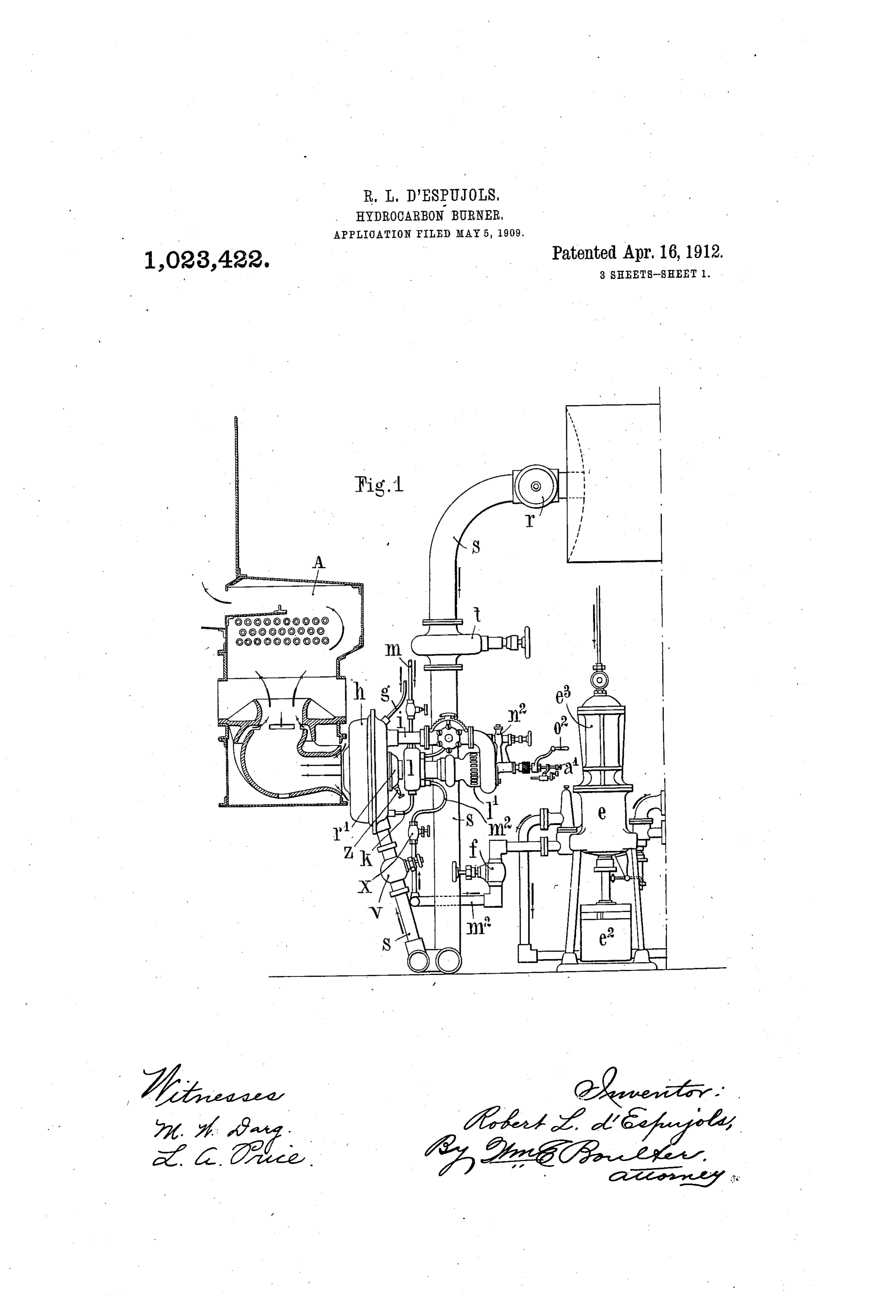
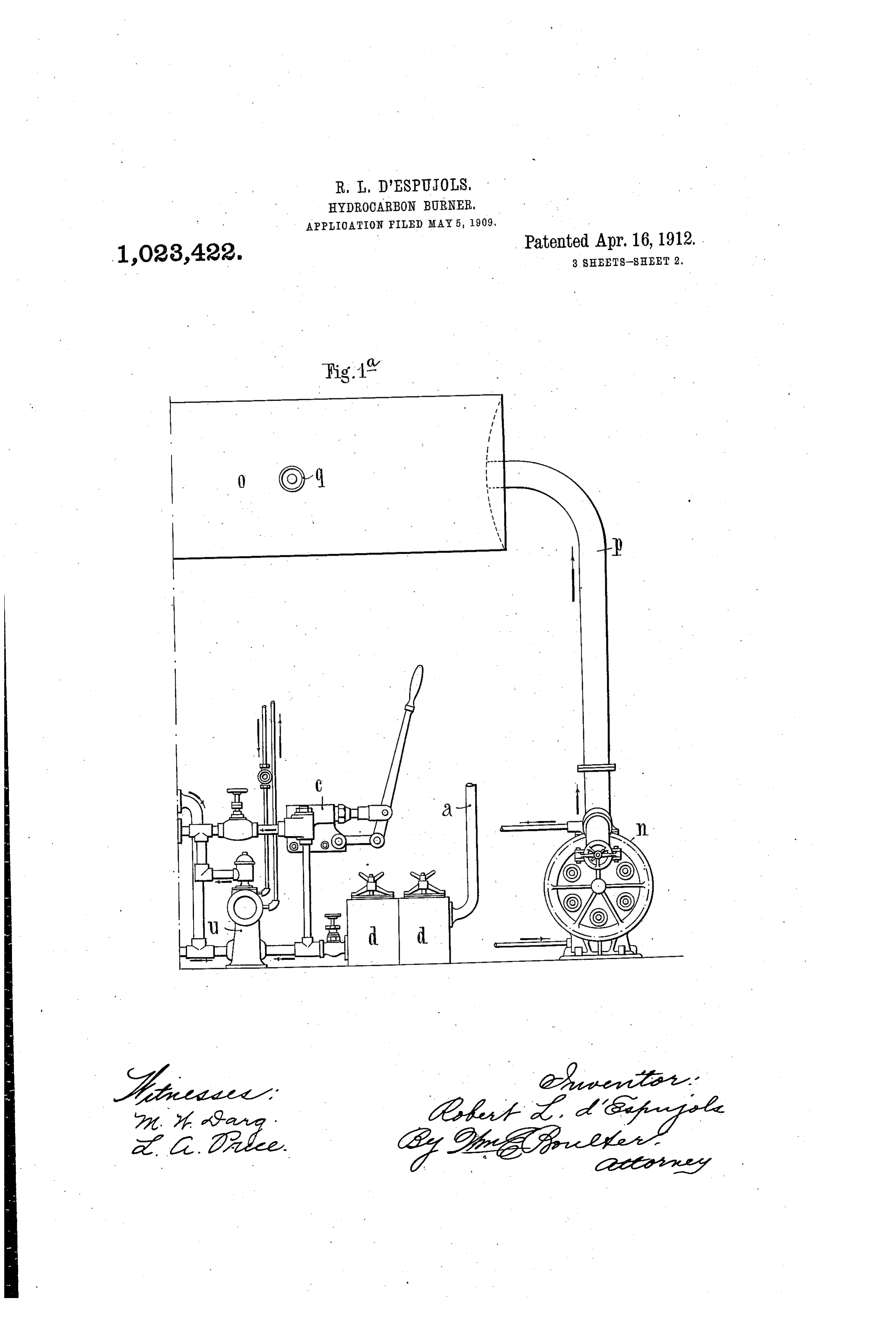
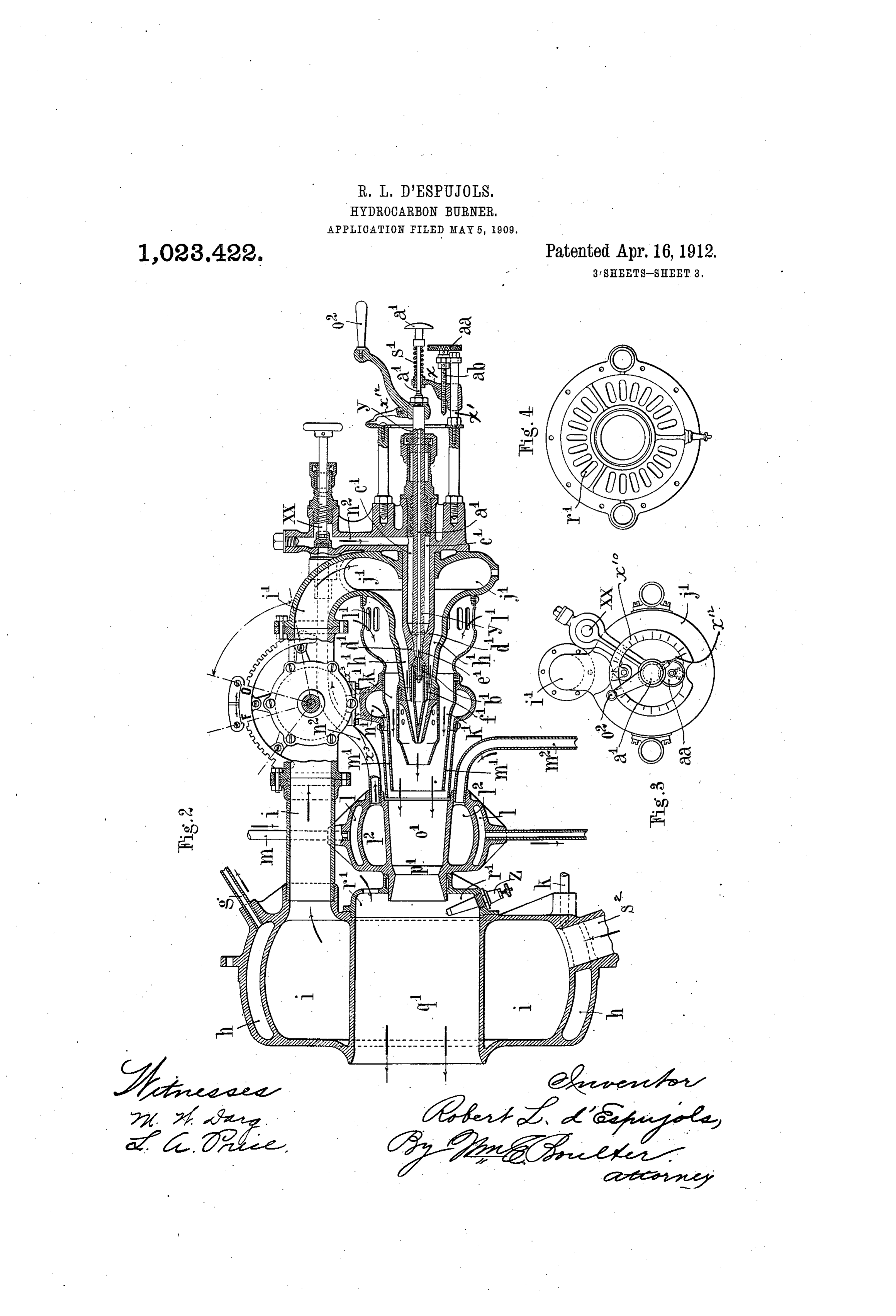
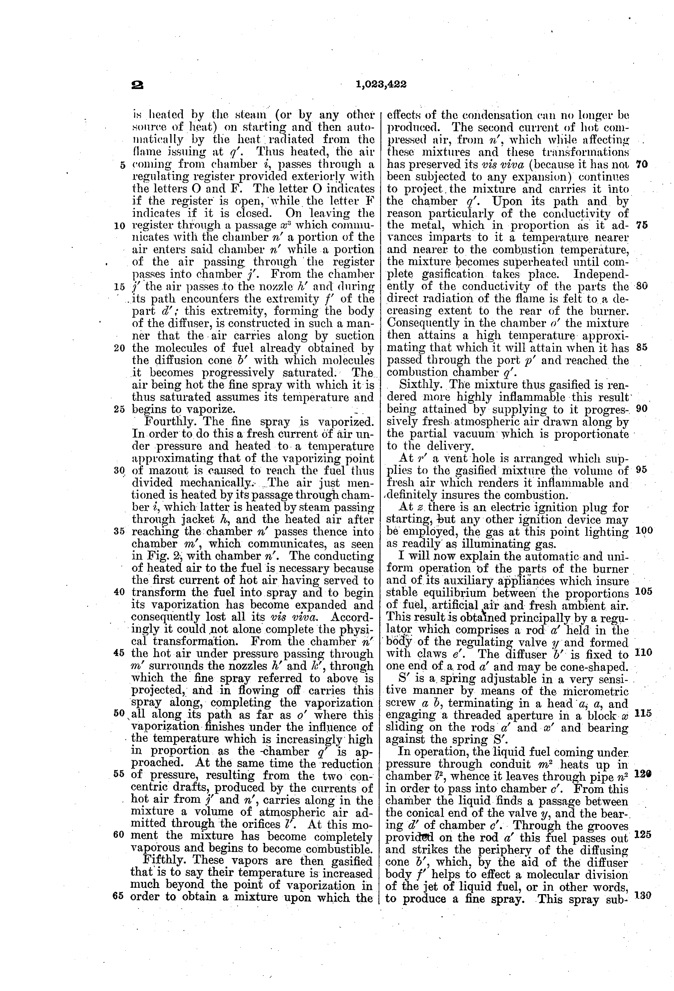
5 struction, arrangement and combination of Secondly. The liquid fuel is conveyed, 70 parts as hereinafter fully described, illus that is to say conducted, to the discharge trated in the drawings and pointed out in orifices, this result being attained by supply the appended claims. ing it under an appropriate pressure. The In the drawings, Figures 1 and 1 show fuel coming from the filter tank d (Fig. 1) an elevation, partly in section, of an appara in communication with suitable reservoirs 75 tus embodying my invention, Fig. 1 showing or magazines (not shown) by means of a the left-hand portion of the apparatus, and pipe a is sucked by the pump at which forces Fig. 1 the right-hand portion. Fig. 2 is it into an apparatus e termed the automatic a vertical sectional view of a horizontal feed compressor. This compressor serves, burner for marine furnaces or the like. Fig. whatever the running of the pump . may 80 3 is an end view of the air-regulating device. be, to regulate the predetermined pressure Fig. 4 is a front view of a portion of the uniform upon any point of the conduit m'. burner. s From this compressor the fuel is sent to the My invention comprises two essential burner through the conduit in passing 30 parts, coöperating together, i. e. the burner, through the stop valves f and a and distrib 85 and the devices for feeding said burner. uted through the conduit n° to the flow ori My invention relates particularly to ap fices a c' (Fig. 2) through which it reaches paratus of the type in which liquid fuel, the part b termed the diffusion cone the ' compressed air, atmospheric air and addi form of which is such that it tends to divide 35 tional compressed air, are supplied through the liquid into molecules. The valve y 90 four concentric passages to the combustion serves to regulate the annular flow orifice chamber, and it is so constructed and ar in proximity to the diffuser b.
ranged as to cause the liquid fuel, the atmos . Thirdly. The fuel is converted into a pheric air, and the primary and secondary fine spray by admitting at the same time a 40 Supplies of compressed air to be heated dur current of compressed air which becomes 95 ing their passage to the combustion cham heated in chamber i, before entering the ber, and thus effect the complete gasification blast pipe h' which surrounds the inlet for of the liquid fuel inside the burner. the liquid. This heated air mixes with the The actions to which the liquid fuel is liquid which leaves the outlet opening with 45 Subjected, the transformations that they a whirling motion and in the form of a fine OO produce, and the manner in which they are spray. The compressed air is obtained by realized, are explained below in detail and the employment of a compressor, pump or in order. blowing engine n (Fig. 1") which delivers First. The fuel is rendered fluid in order through a pipe p into a reservoir o thence 05 50 that it may circulate freely in the appara distributes it through a valver to a gas pipe tus. With this object it is heated but not S to which a pressure regulator it is fitted. excessively which presents the further ad The air reaches the burner through port S vantage, while raising its temperature pro in the chamber i (Fig. 2) likewise provided gressively, of bringing it closer to its point with a steam heating chamber h, with con of vaporization. This fluidity is obtained in duits A. g for admitting the steam, where it 110
Page 5
is heated by the steam (or by any other effects of the condensation can no longer be source of heat) on starting and then auto produced. The second current of hot com matically by the heat radiated from the pressed air, from n, which while affecting flame issuing at q'. Thus heated, the air these mixtures and these transformations conning from chamber i, passes through a has preserved its vis iva (because it has not 70 regulating register provided exteriorly with been subjected to any expansion), continues the letters O and F. The letter O indicates to project, the mixture and carries it into if the register is open, while the letter F the chamber 7. Upon its path and by
indicates if it is closed. On leaving the reason particularly of the conductivity of O register through a passage a' which commu the metal, which in proportion as it ad 75 nicates with the chamber in a portion of the vances imparts to it a temperature nearer air enters said chamber n' while a portion and nearer to the combustion temperature, of the air passing through the register the mixture becomes superheated until com passes into chamber i'. From the chamber plete gasification takes place. Independ 5 i' the air passes to the nozzle h and during ently of the conductivity of the parts the its path encounters the extremity f' of the direct radiation of the flame is felt to a de part d' this extremity, forming the body creasing extent to the rear of the burner. of the diffuser, is constructed in such a man Consequently in the chamber o' the mixture ner that the air carries along by suction then attains a high temperature approxi 85 20 the molecules of fuel already obtained by mating that which it will attain when it has the diffusion cone b' with which molecules passed through the port p' and reached the it becomes progressively saturated. The combustion chamber q'.
air being hot the fine spray with which it is Sixthly. The mixture thus gasified is ren thus saturated assumes its temperature and dered more highly inflammable this result 90 begins to vaporize. -. being attained by supplying to it progres Fourthly. The fine spray is vaporized. sively fresh atmospheric air drawn along by In order to do this a fresh current of air un the partial vacuum which is proportionate der pressure and heated to a temperature to the delivery.
approximating that of the vaporizing point At a vent hole is arranged which sup 30 of mazout is caused to reach the fuel thus plies to the gasified mixture the volume of 95 divided mechanically. The air just men fresh air which renders it inflammable and tioned is heated by its passage through cham definitely insures the combustion. ber i, which latter is heated by steam passing At 2, there is an electric ignition plug for through jacket h, and the heated air after starting, but any other ignition device may 35 reaching the chamber in passes thence into be employed, the gas at this point lighting 100 chamber m, which communicates, as seen as readily as illuminating gas. in Fig. 2, with chamber n?. The conducting I Will now explain the automatic and uni of heated air to the fuel is necessary because form operation of the paarts of the burner the first current of hot air having served to and of its auxiliary appliances which insure 40 transform the fuel into spray and to begin stable equilibrium between the proportions 05 its vaporization has become expanded and of fuel, artificial air and fresh ambient air. consequently lost all its vis viva. Accord This resultis obtained principally by a regu. ingly it could not alone complete the physi lator which comprises a rod a held in the cal transformation. From the chamber n/ body of the regulating valve of and formed 45 the hot air under pressure passing through with claws e'. The diffuser b is fixed to O m surrounds the nozzles h’ and k, through one end of a rod a' and may be cone-shaped. which the fine spray referred to above is S is a spring adjustable in a very sensi projected, and in flowing off carries this tive manner by means of the micrometric spray along, completing the vaporization Screw a b, terminating in a heada, a, and 5 50 all along its ath as far as o' where this engaging a threaded aperture in a block a vaporization finishes under the influence of sliding on the rods a' and a' and bearing the temperature which is increasingly high against the spring S.
in proportion as the -chamber q is ap In operation, the liquid fuel coming under proached. At the same time the reduction pressure through conduit m heats up in 55 of pressure, resulting from the two con chamber 7, whence it leaves through pipe n° 2) centric drafts, produced by the currents of in order to pass into chamber c'. From this hot air from i and n, carries along in the chamber the liquid finds a passage between mixture a volume of atmospheric air ad the conical end of the valvey, and the bear mitted through the orifices Z. At this mo ing d of chamber o. Through the grooves
ment the mixture has become completely provided on the rod a this fuel passes out 25 vaporous and begins to become combustible. and strikes the periphery of the diffusing Fifthly. These vapors are then gasified cone b, which, by the aid of the diffuser that is to say their temperature is increased body if helps to effect a molecular division much beyond the point of vaporization in of the jet of liquid fuel, or in other words, 65 order to obtain a mixture upon which the to produce a fine spray. This spray sub 30
Page 6
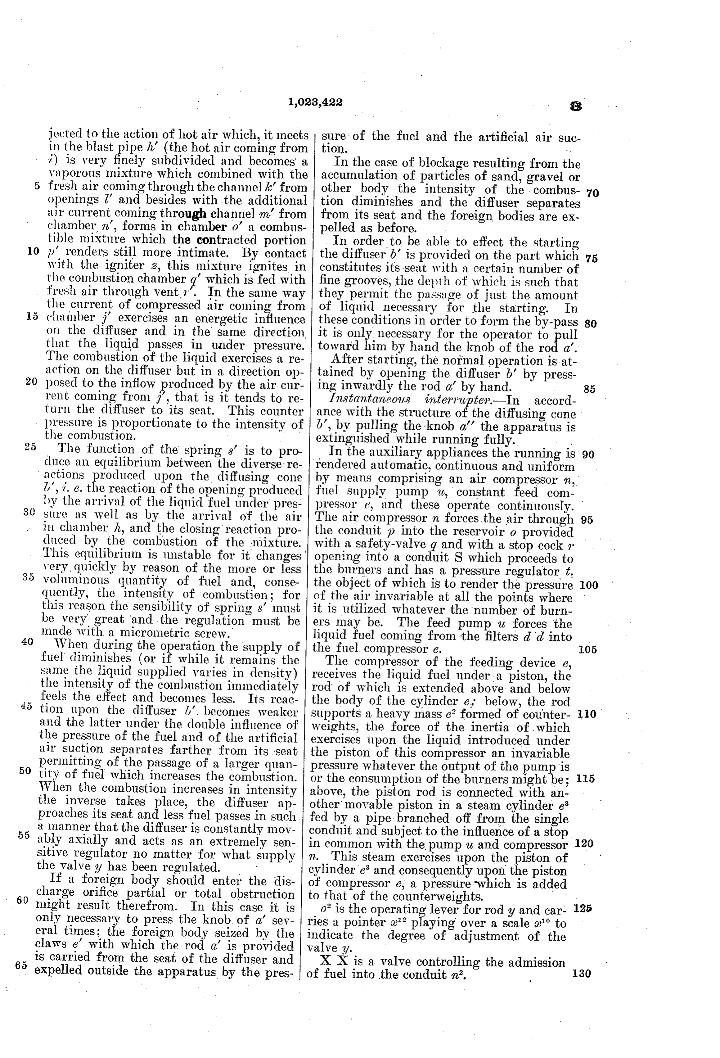
jected to the action of hot air which, it meets sure of the fuel and the artificial air suc in the blast pipe h' (the hot air coming from tion.
i) is very finely subdivided and becomes a In the case of blockage resulting from the vaporous mixture which combined with the accumulation of particles of sand, gravel or fresh air coming through the channelk' from other body the intensity of the combus openings 2 and besides with the additional tion diminishes and the diffuser separates 70 air current coming through channel m, from from its seat and the foreign bodies are ex chamber n, forms in chamber o' a combus pelled as before.
tible mixture which the contracted portion In order to be able to effect the starting O p' renders still more intimate. By contact the diffuser b is provided on the part which with the igniter 2, this mixture ignites in constitutes its seat with a certain number of 75 the combustion chamber q' which is fed with fine grooves, the depth of which is such that fresh air through vent. '. In the same way the current of compressed air coming from they of permit the passage of just the amount liquid necessary for the starting. In 15 chamber i' exercises an energetic influence these conditions in order to form the by-pass 80 on the diffuser and in the same direction. it is only necessary for the operator to pull that the liquid passes in under pressure. toward him by hand the knob of the rod a'. The combustion of the liquid exercises a re After starting, the normal operation is at action on the diffuser but in a direction op 20 posed to the inflow produced by the air cur tained by opening the diffuserb' by press ing inwardly the rod a' by hand.
rent coming from j', that is it tends to re Instantaneous interrupter-In accord 85 turn the diffuser to its seat. This counter ance with the structure of the diffusing cone pressure is proportionate to the intensity of b', by pulling the knob a' the apparatus is the combustion. extinguished while running fully.
The function of the springs' is to pro In the auxiliary appliances the running is 90 duce an equilibrium between the diverse re rendered automatic, continuous and uniform actions produced upon the diffusing cone by means comprising an air compressor n, l', i.e. the reaction of the opening produced fuel Supply pump u, constant feed com ly the arrival of the liquid fuel under pres pressor e, and these operate continuously. sure as well as by the arrival of the air The air compressor n forces the air through 95 in chamber h, and the closing reaction pro the conduit p into the reservoir o provided duced by the combustion of the mixture.
This equilibrium is unstable for it changes with a safety-valve 9 and with a stop cock opening into a conduit S which proceeds to very quickly by reason of the more or less the burners and has a pressure regulator t. 35 voluminous quantity of fuel and, conse the object of which is to render the pressure 00 Quently, the intensity of combustion; for of this reason the sensibility of springs' must it istheutilized air invariable at all the points where be very great and the regulation must be ers may be. whatever The feed the number of burn pump u forces the made with a micrometric screw.
When during the operation the supply of the fuel compressor e. the filters did into liquid fuel coming from fuel diminishes (or if while it remains the The compressor of the feeding device e, same the liquid supplied varies in density) receives the liquid fuel under a piston, the the intensity of the combustion immediately rod of which is extended above and below
feels the effect and becomes less. Its reac the body of the cylinder e, below, the rod tion upon the diffuser b. becomes weaker and the latter under the double influence of supports a heavy mass e” formed of counter 110 weights, the force of the inertia of which the pressure of the fuel and of the artificial exercises upon the liquid introduced under air Suction separates farther from its seat the piston of this compressor an invariable
permitting of the passage of a larger quan pressure whatever the output of the pump is tity of fuel which increases the combustion. or the consumption
When the combustion increases in intensity above, the piston rodof istheconnected burners might be; 5 with an the inverse takes place, the diffuser ap other movable piston in a steam cylinder proaches its seat and lessfuel passes in such fed by a pipe branched off from the singlee 55 a manner that the diffuser is constantly mov conduit and subject to the influence of a stop ably axially and acts as an extremely sen sitive regulator no matter for what supply inn. common
This with the pump u and compressor 120 steam exercises upon the piston of the valvey has been regulated. cylinder e and consequently upon the piston If a foreign body should enter the dis of compressor e, a pressure which is added 60 charge orifice partial or total obstruction to that of the counterweights. night result therefrom. In this case it is
Only necessary to press the knob of a sev rieso' aispointer the operating lever for rody and car 125 a playing over a scale a to eral times; the foreign body seized by the indicate the degree of adjustment of the claws e' with which the rod a' is provided valvey.
65 is carried from the seat of the diffuser and expelled outside the apparatus by the pres X X is a valve controlling the admission 130 of fuel into the conduit n°.
Page 7
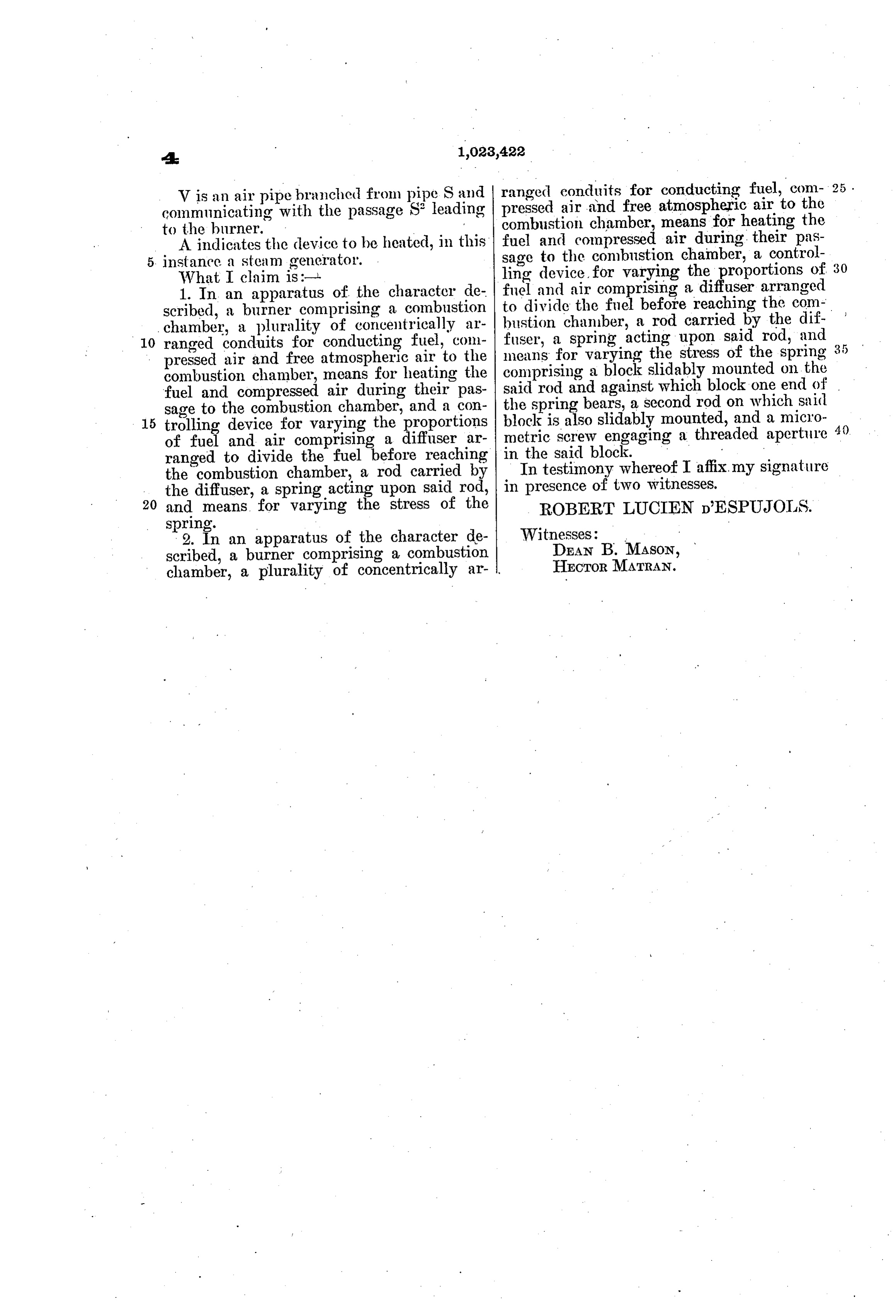
V is an air pipe branched from pipe S and ranged conduits for conducting fuel, com 25 . pressed air and free atmospheric air to the communicating with the passage S leading to the burner. combustion chamber, means for heating the fuel and compressed air during their pas
A indicates the device to be heated, in this sage instance a steam generator. to the combustion chamber, a control What I claim is:-l. ling device, for varying the proportions of 30 1. In an apparatus of the character de fuel to and air comprising a diffuser arranged divide the fuel before reaching the com scribed, a burner comprising a combustion bustion chaniber, a rod carried by the dif chamber, a plurality of concentrically ar fuser, a spring acting upon said rod, and 10 ranged conduits for conducting fuel, com means for varying the stress of the spring 3 5 pressed air and free atmospheric air to the comprising combustion chamber, means for heating the a block slidably mounted on the fuel and compressed air during their pas said rod and against which block one end of sage to the combustion chamber, and a con the spring bears, a second rod on which said 15 trolling device for varying the proportions block is also slidably mounted, and a micro 40 of fuel and air comprising a diffuser ar in metric screw engaging a threaded aperture ranged to divide the fuel before reaching Inthetestimony
whereof I affix. my signature the combustion chamber, a rod carried by in presence of two witnesses. the diffuser, a spring acting upon said rod, 20 and means for varying the stress of the ROBERT LUCIEN DESPUJOILS. Spring.
2. In an apparatus of the character de Witnesses:
scribed, a burner comprising a combustion DEAN B. MASON, chamber, a plurality of concentrically ar- . HECTORMATRAN.
Provenance
- Collection
- Cited prior art
- Original PDF
- patentimages.storage.googleapis.com →
- Filed
- 1909-05-05
- Pages
- 7
- Method
- pdftotext (the PDF's own text layer) + pdftoppm 300dpi page scans
- Source
- Google Patents bibliographic record
- Granted
- 1912-04-16
- Inventors
- Robert Lucien D Espujols
- Transcribed from
- patentimages.storage.googleapis.com →