patent · US20070248509A1
Method and apparatus for generating hydrogen gas on demand from water with recovery of water and complete recycling of consumable material
25 October 2007
Page 1 — bibliographic record
(19) United States (12) Patent Application Publication (10) Pub. No.: US 2007/0248509 A1
Brinkley, III (43) Pub. Date: Oct. 25, 2007 (54) METHOD AND APPARATUS FOR (60) Provisional application No. 60/422,159, filed on Oct. GENERATING HYDROGEN GAS ON 29, 2002.
DEMAND FROM WATER WITH RECOVERY
OF WATER AND COMPLETE RECYCLING Publication Classification
OF CONSUMABLE MATERAL
(76) Inventor: William J. Brinkley III, Iuka, MS (52) U.S. Cl. .............................................................. 422/187 (US) (57) ABSTRACT
A hydrogen gas generation system for vehicles and station
Correspondence Address: ary power applications comprises a trio of rigid, cylindrical Stephen D. Carver high pressure reservoir tanks interconnected with Suitable Suite 800 fittings and pipelines. A water holding tank alternatively 2024 Arkansas Valley Drive stores hydroxide solution, or transfers it to an adjacent gas Little Rock, AR 72212-4147 (US) generating tank, containing a plurality of tubular, aluminum fuel rods. When the holding tank is suitably pressurized, (21) Appl. No.: 11/821,024 hydroxide solution is transferred into the generating tank to start a reaction with a plurality of elongated, tubular alumi (22) Filed: Jun. 21, 2007 num rods disposed therewithin. Conversely, the liquid con tents of the generating tank can be forcibly pressured back
Related U.S. Application Data into the holding tank to stop the gas generation reaction. High pressure hydrogen gas is humidified in the third tank (62) Division of application No. 10/691,049, filed on Oct. prior to combustion as fuel. Humidified hydrogen is trans 23, 2003. ferred via control valves to the application.
Page 2
Drawing sheet — no readable text.
Page 3
Drawing sheet — no readable text.
Page 4
Drawing sheet — no readable text.
Page 5
Drawing sheet — no readable text.
Page 6
Drawing sheet — no readable text.
Page 7
US 2007/0248509 A1 Oct. 25, 2007
METHOD AND APPARATUS FOR GENERATING typically removed by a heat exchanger. In the heat pump HYDROGEN GAS ON DEMAND FROM WATER mode of operation, the above cycle is sequentially repeated WITH RECOVERY OF WATER AND COMPLETE through a series of reactors so that the heat of absorption is RECYCLING OF CONSUMABLE MATERAL sequentially added to the heat exchange fluid. CROSS REFERENCE TO RELATED 0009 U.S. Pat. No. 4,085,709 issued Apr. 25, 1978 APPLICATION discloses a fuel system for vehicles that generates hydrogen gas electrically and stores it on board the vehicle for 0001. This is a divisional application based upon a prior combustion. The system includes a gas cylinder, an electro Utility Patent application entitled Method and Apparatus for lyZer connected to the gas cylinder, and a power Supply Generating Hydrogen Gas on Demand from Water with connected to the electrolyzer, and a gas storage cylinder. Recovery of Water and Complete Recycling of Consumable 0010 U.S. Pat. No. 4,090,361 discloses improved-power Material, Ser. No. 10/691,049, filed Oct. 23, 2003, which cycles for using the hydride-dehydride-hydrogen (HDH) was in turn based upon a previously filed provisional appli power cycle to produce hydrogen gas continuously at high cation, Ser. No. 60/422,159, filed Oct. 29, 2002, which was pressure and elevated temperatures. This gas can be used to entitled Method and Apparatus for Generating Hydrogen produce power and refrigeration. The hydrogen gas can be Gas on Demand from Water with Recovery of Water and passed directly to an expansion device, such as a turbine, or Complete Recycling of Consumable Material, upon which the hydrogen gas can be the working fluid used to transfer priority is claimed. heat to a secondary system. Terry discloses using the HDH cycle to continuously produce hydrogen gas to drive an
BACKGROUND OF THE INVENTION expansion device Such as a turbine.
0002) 1. Field of the Invention 0.011 U.S. Pat. No. 5.228,529 issued Jul. 20, 1993 0003. The present invention relates generally to the gen employs magnesium anodes in renewable fuel cells that eration of hydrogen gas and the employment of it as a produce hydrogen gas on demand for powering a vehicle. In combustible fuel. More particularly, the present invention operation the magnesium anode is converted into magne relates to an “on-demand chemical system for producing sium hydroxide precipitate, which is removed and collected hydrogen gas and using it for propulsion, wherein critical for recycling. The magnesium anode and electrolyte is elements are recovered and recycled. replaced to recharge the fuel cell. 0004 2. Description of the Related Art 0012 U.S. Pat. No. 5.286,473 issued Feb. 15, 1994 discloses a system reacting an alkali metal with an ionizable 0005. It has long been recognized by those skilled in the hydrogen compound selected from the group consisting of art that hydrogen, the most abundant element in the uni hydrochloric acid, water or mixtures thereof to produce verse, is relatively cheap and plentiful. Long recognized as hydrogen and an alkali metal chloride or alkali metal a basic constituent of water, many have dreamt of its use as hydroxide, depending upon whether hydrochloric acid or a fuel. Accordingly, the prior art reflects numerous diverse water is used to react with the alkali metal. The alkali metal attempts at recovering or generating hydrogen, and a virtual chloride is recycled. The hydrochloric acid is recycled to plethora of patents directed to propulsion systems and produce hydrogen by reaction with the alkali metal. The energy storage or transfer systems involving it. aluminum hydroxide formed can be electrolyzed to alumi 0006 U.S. Pat. No. 3,943,719. discloses a power system num metal and water to provide a method of recovering comprising a reactor in which a hydride absorbs hydrogen at aluminum metal from aluminum scrap which previously has low pressure and low temperature, and then heating the not be readily recyclable.
hydride at constant Volume so as to release large quantities 0013 U.S. Pat. No. 5,293,857 issued Mar. 15, 1994 of hydrogen at high temperatures and pressure. This released shows a combination wherein hydrogen gas fuel is com hydrogen is used to produce power and yield refrigeration. busted within an internal combustion engine. The proportion Electrical power can be generated by expanding the released of hydrogen to oxygen is approximately 2:1, and the density hydrogen through a turbine or other power producing of hydrogen is regulated so that the burn rate of the com devices. bined gas mixture approximates that of a fossil fuel. 0007 U.S. Pat. No. 4,005,185 issued Jan. 25, 1977 dis 0014 U.S. Pat. No. 5,634.341 issued Jun. 3, 1997 and closes a method for generating hydrogen using metallic Zinc U.S. Pat. No. 5,867,978 issued Feb. 9, 1999 disclose related within an aqueous Solution, preferably ammonium carbon systems for generating hydrogen gas from a charge of fuel ate.
comprising lithium, aluminum or alloys thereof. The fuel is 0008 U.S. Pat. No. 4,055.962 discloses a hydrogen heated until molten, and sprayed with water within a pres hydride absorption system comprising a sequential method sure vessel. The process may be employed with either a of reversibly combining hydrogen with a hydride-forming Rankine-cycle engine or a hydrogen-oxygen fuel cell sys material, heating the hydride at constant volume, and means tem.
for conveying hydrogen between the reactors. In the power 0.015 U.S. Pat. No. 5,728,464 issued Mar. 17, 1998 or heat pump cycle, the hydride in a first reactor is heated to discloses an on-demand hydrogen generation system for desorb hydrogen gas. The gas flows to a second hydride bed propulsion. Sodium pellets are exposed to water to generate in a second reactor where it is absorbed at a temperature hydrogen.
lower then the temperature of desorption of the first hydride bed. Absorption of the hydrogen by the second reactor 0016 U.S. Pat. No. 5,830,426 issued Nov. 3, 1998 illus releases the heat of absorption. This heat of absorption is trates an aqueous hydrogen generation process wherein an
Page 8
US 2007/0248509 A1 Oct. 25, 2007
electrical vehicle utilizes a hydrogen-air fuel cell to power 0022 Humidified hydrogen is transferred via control electrical drive motors. Hydrogen fuel is supplied on valves to the application. Preferably, it is delivered to demand by a reactor bed of iron particles that reacts with suitable fuel injectors that feed an internal combustion water in the presence of an alkali hydroxide catalyst. Potas motor. The normally hot, low pressure gas exhaust is pref sium hydroxide in a range of concentrations between 50 to erably vented through the engine exhaust manifold into a 60 percent by weight is preferred. Hydrogen gas generated condenser for cooling and recycling. Spent aluminum detri in situ is stored within a compartment containing iron tus may also be recovered for recycling. materials. Iron oxide produced during hydrogen generation may be recovered and recycled. 0023 Thus a basic object is to generate a safe, powerful, and non-polluting energy source for vehicles.
0017 U.S. Pat. No. 5,865,262 issued Feb. 2, 1999 dis 0024. Another basic object is to reduce the contemporary closes a self-propelled hydrogen fuel system. A hydrogen reliance upon fossil fuels.
gas tank receives gas from a chemical reactor equipped with a catalyst. Alcohol is vaporized in an heat exchanger, 0025. Another object of my invention is to safely and reacting with the catalyst in the chemical reactor and form quickly produce hydrogen gas in an "on demand manner ing hydrogen gas and acetic ether, which are stored in suitable for use with vehicles. appropriate tanks.
0026 Still another object of my invention is to provide an 0018 U.S. Pat. No. 5,867,978 issued Feb. 9, 1999 dis affordable and cost-efficient replacement fuel source for closes a system for generating hydrogen for generating vehicles.
hydrogen gas from a charge of fuel selected from the group 0027. Another object is to safely and dependably turn on consisting of lithium and alloys of lithium and aluminum. and/or turn off the chemical production of hydrogen gas, The charge of fuel is placed into an enclosed vessel, then thereby providing a hydrogen propulsion system Suitable for heated until it is molten. A reactant consisting of water is practical use.
introduced into the vessel, as by spraying from a nozzle, for reaction with the charge of fuel resulting in the production 0028. Yet another important object of my invention is to of hydrogen gas and heat which are withdrawn from the provide an environmentally friendly, non-polluting energy vessel. Prior to initiation of the process, an inert gas atmo source for vehicles.
sphere. Such as argon, may be imparted to the interior of the vessel. A sufficiently large mass flow of the reactant through 0029. Thus, another object is to provide an energy source the nozzle is maintained to assure that there be no diminu that can be easily and economically renewed and/or stored. tion of flow resulting from the formation on the nozzle of 0030 Still another object is to recycle and reuse various fuel and chemical compounds of the fuel. Optimum charges constituent materials and chemicals utilized in the preferred of the fuel are application specific and the ranges of the reaction process.
constituents are dependent upon the particular use of the system. The process and apparatus of the invention may be 0031. A further object is to provide a low-cost energy incorporated into a Rankine cycle engine or into a hydrogen source for vehicles.
oxygen fuel cell system.
0032. Yet another object is to convert a fluid and solid
BRIEF SUMMARY OF THE INVENTION into raw hydrogen suitable for use within modern internal combustion engines.
0019. This invention provides a unique, on-demand 0033. A related object is to regulate and control the hydrogen production and generation system. Importantly, humidity if the propelling hydrogen generated through the the hydrogen gas collected within the reaction generator process.
tank is first humidified prior to combustion.
0020 My preferred hydrogen generation system com 0034. Another important object is to recycle the alumi num control rods preferably employed in the reaction.
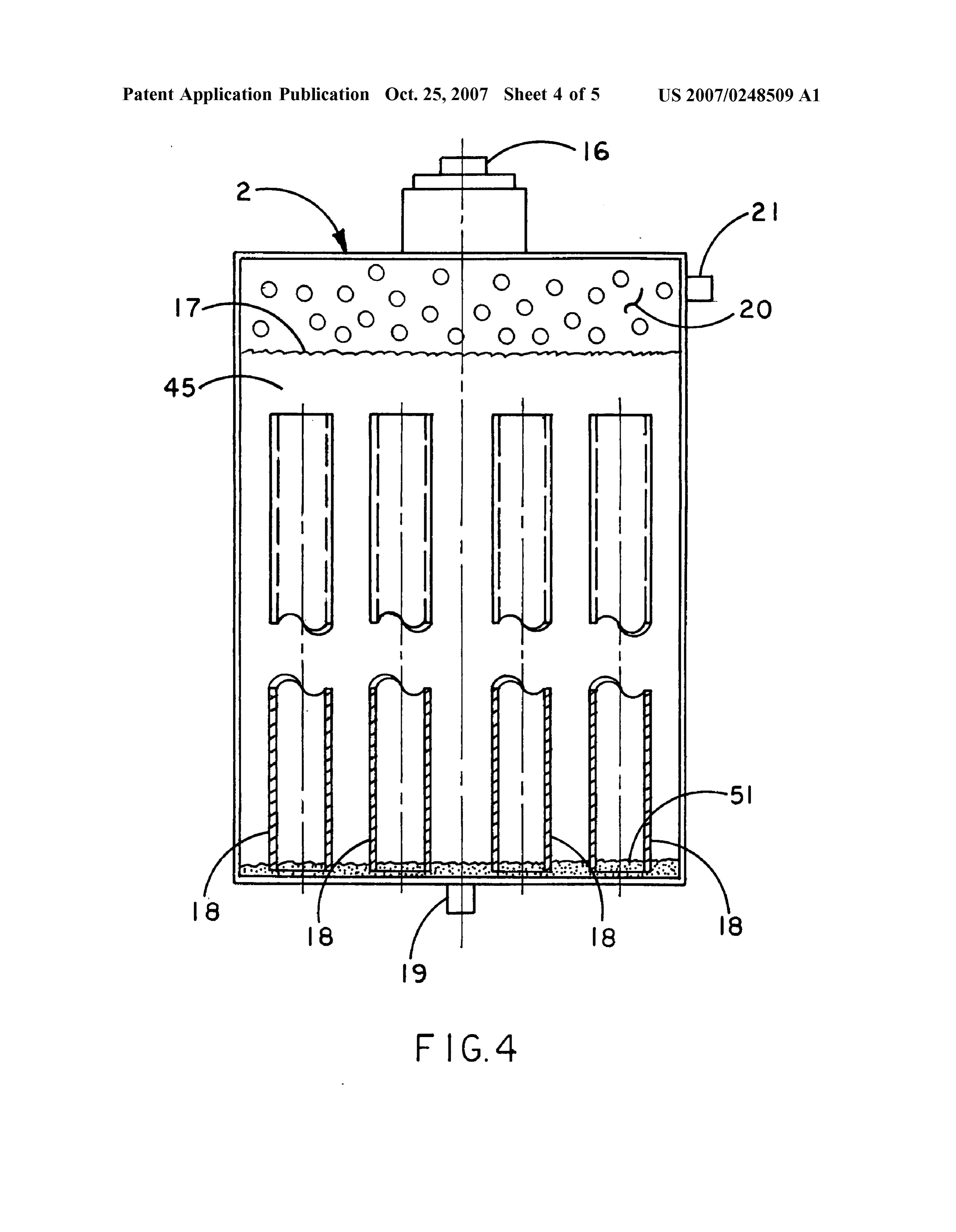
prises a plurality of interconnected holding tanks, and a plurality of interconnected valves and control pipelines. A 0035 Conversely, an important object is to optimize the first, rigid upright, cylindrical holding tank acts as a reser rate at which the moisture-controlled hydrogen gas gener voir and as a return destination, holding, in the best mode, ated though my system may be liberated for use at a rate of approximately twelve gallons of hydroxide solution. The consumption commensurate with the energy use of a trav holding tank is connected to a gas generating tank, which eling vehicle.
contains a plurality of tubular, aluminum fuel rods. The 0036) Another basic object is to provide hydrogen gas to holding tank can be pressurized to transfer hydroxide solu propel vehicles or power various power plants. tion into the generating tank to start the reaction; conversely, the liquid contents of the generating tank, even while 0037 Another important object is to de-salinate water. It actively reacting, can be emptied and forced into the holding is a feature of this invention that sea water (i.e., salt water) tank to stop the reaction, as when a vehicle powered by the may be substituted for the tap water or distilled water system stops or rests. normally used, and it can be received from the condenser as 0021 Low pressure hydrogen gas is humidified prior to drinking water, on a one-gallon-in, one-gallon-out basis. combustion as fuel. The gas output of the generating tank 0038. These and other objects and advantages of the feeds an adjacent humidifier tank. Humidity of the hydrogen present invention, along with features of novelty appurte is adjusted to approximately 100% in this manner to pro nant thereto, will appear or become apparent in the course of mote clean and efficient burning. the following descriptive sections.
Page 9
US 2007/0248509 A1 Oct. 25, 2007
BRIEF DESCRIPTION OF THE SEVERAL ture to approximately 180 degrees Fahrenheit. Alternatively VIEWS OF THE DRAWINGS a twelve-volt D.C. element may be used.
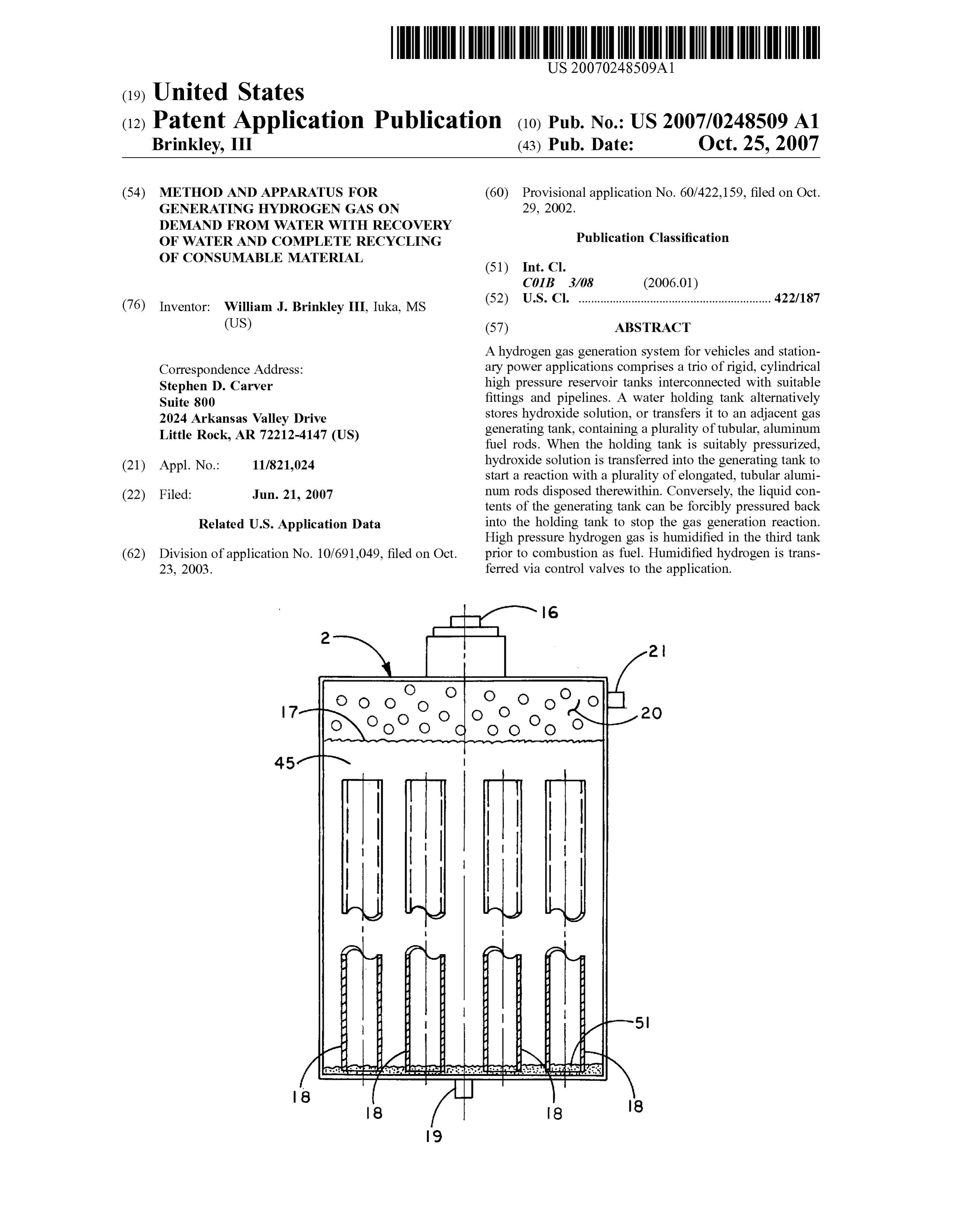
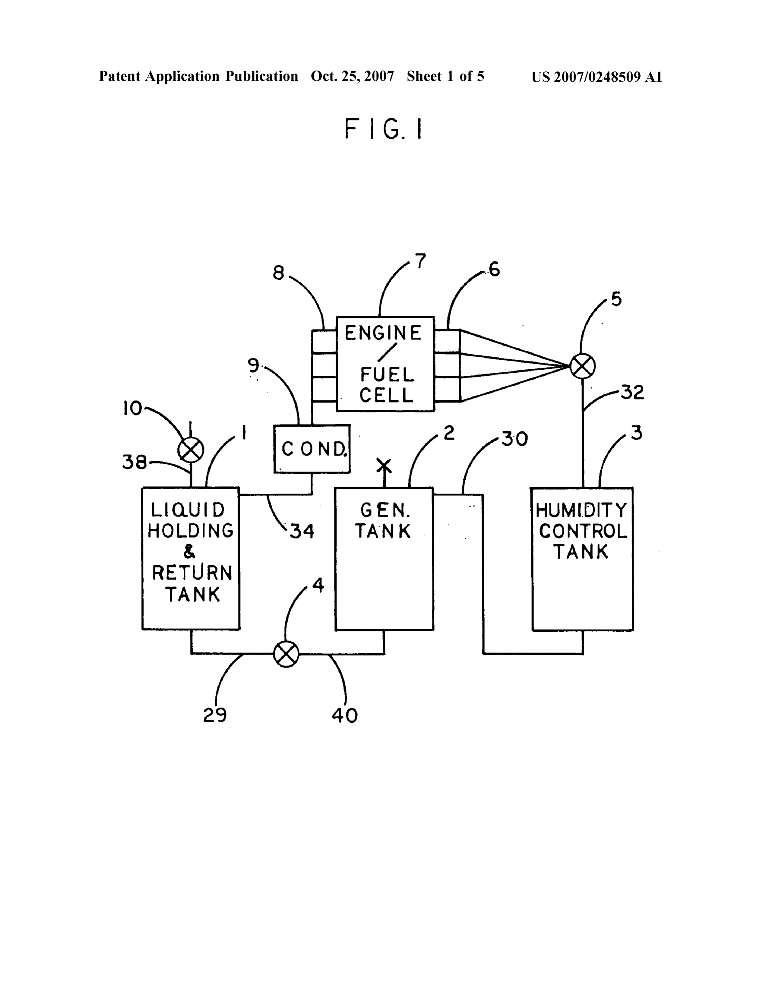
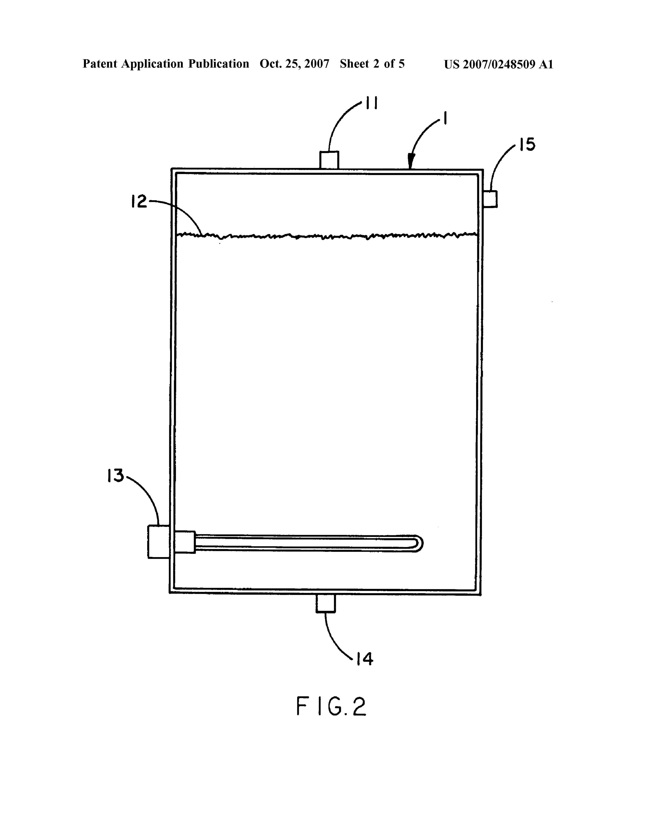
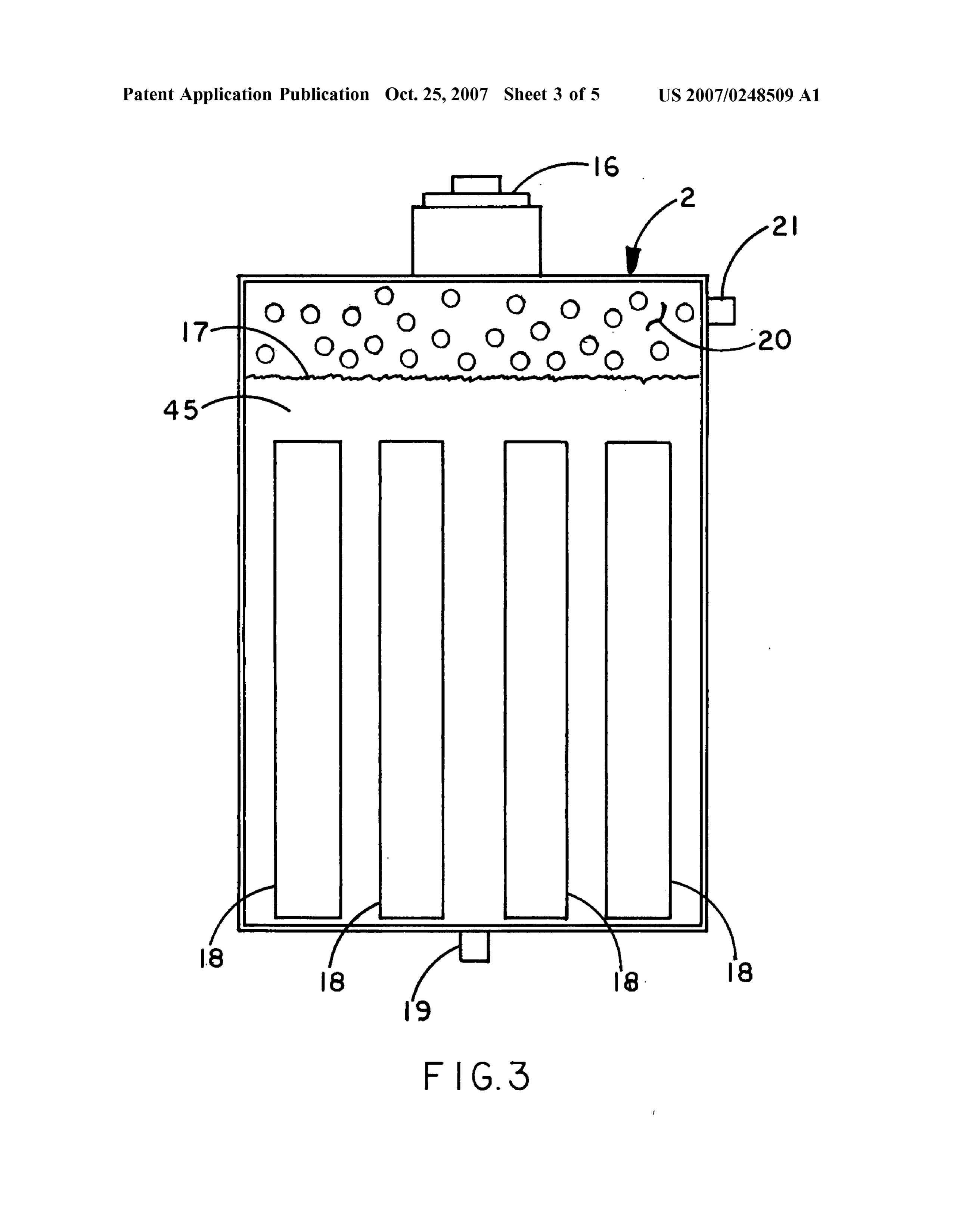
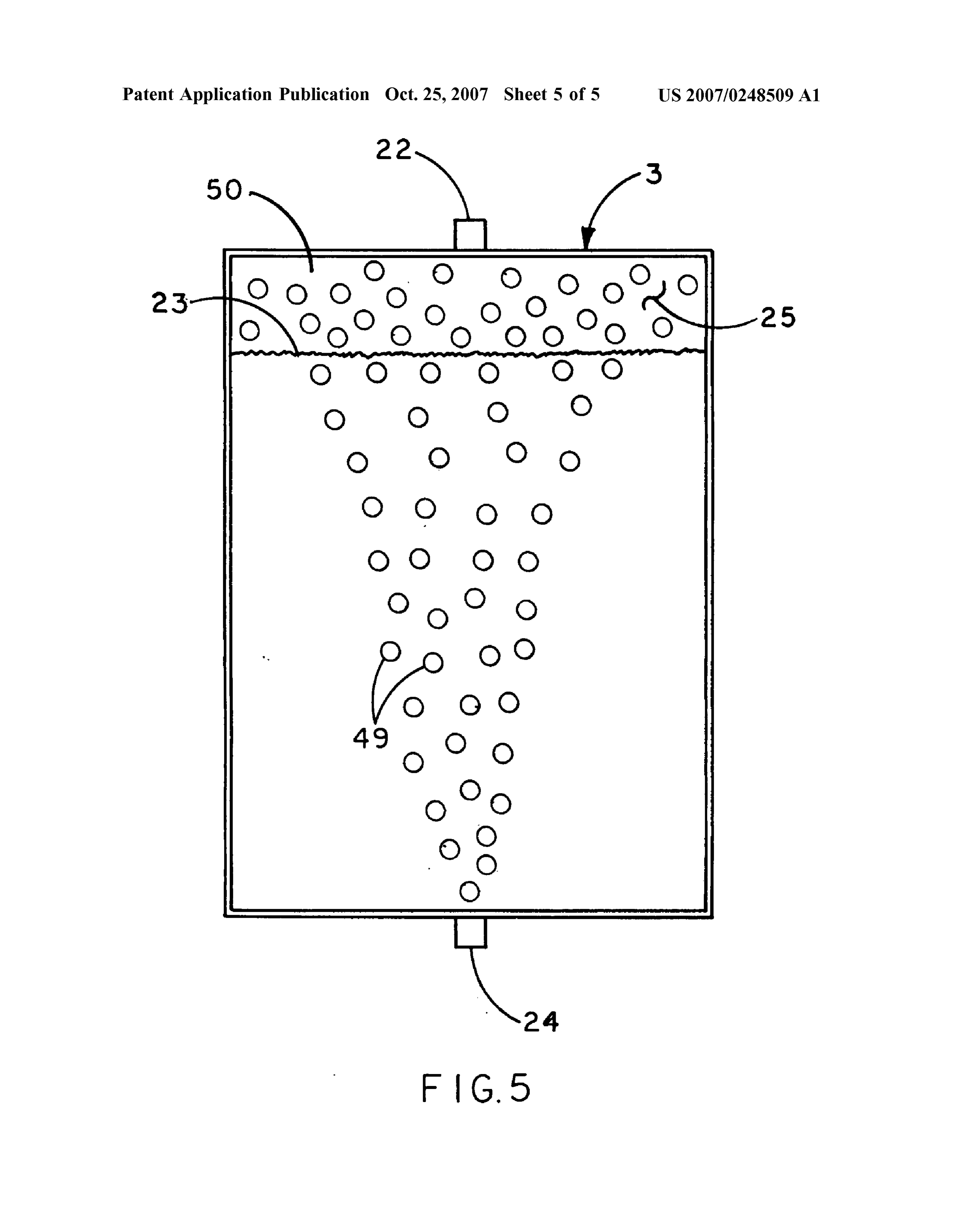
0039. In the following drawings, which form a part of the 0.048. With joint reference now directed to FIGS. 3 and 4, specification and which are to be construed in conjunction tank 2 comprises a rigid, upright, generally cylindrical therewith, and in which like reference numerals have been enclosure like the other tanks in the system. Tank 2 can be employed throughout wherever possible to indicate like selectively filled with liquid from tank 1 via line 40 (FIG. 1) parts in the various views: and inlet fitting 19 (FIG. 3). External pressure is applied to 0040 FIG. 1 is an overall block diagram of my preferred gas outlet 21, as explained later. The reference numeral 17 hydrogen gas generation system; broadly designates the hydroxide solution forced into tank 2 for hydrogen generation. A large inspection fitting 16 at the 0041 FIG. 2 is an enlarged, vertical sectional view of the top of tank 2 (FIGS. 3, 4) can be removed to permit user liquid holding tank of FIG. 1; access into the tank interior 45. The reference numeral 20 (FIGS. 3, 4) broadly designates hydrogen gas bubbles that 0.042 FIG. 3 is an enlarged, vertical sectional view of the are yielded upon the reaction between the solution 17, and generating tank of FIG. 1; the plurality of aluminum tubes 18 disposed in an orderly 0.043 FIG. 4 is a fragmentary, sectional view of the gas and regular array within the tank 2. When fitting 16 is generating tank, with portions broken away for clarity or removed, and after draining out fluid 17, these elongated, omitted for brevity; and, cylindrical aluminum tubes 18 may be placed within the tank. Afterwards, returning fitting 16 atop the tank 2 allows 0044 FIG. 5 is an enlarged, vertical sectional view of the the interior to be sealed and pressured. humidity control tank.
0049. As best seen in FIG. 4, each of the fuel tubes 18 is
DETAILED DESCRIPTION OF THE preferably tubular, and preferably they comprise aluminum. INVENTION In the best mode the tubes are 2.5 inches outer diameter, with a 2.0 inch inner diameter. Since the tubes 18 have a hollow 0045 Turning now to the drawings, FIG. 1 shows the interior, a maximal exposure of metal to hydroxide Solution overall block diagram of the preferred system. A large, results, so the reaction speed is increased. In fact, the upright, cylindrical liquid holding tank 1 acts as a reservoir reaction is highly exothermic, and generates hydrogen under and as a return destination. Liquid preferably comprising considerable pressure (i.e., 20-300 PSI). As the reaction water and potassium hydroxide can enter tank 1 via valve continues, the aluminum tubes reduce to powder. The alu 10, and it can exit via line 29 and shut-off valve 4. When minum hydroxide waste collects as dust or fine grained valve 4 is opened, fluid, preferably a hydroxide solution, powder 51 (FIG. 4) at the bottom of the tank 2, and it can flows into generating tank 2, via a conduit as explained be removed during regular maintenance and periodic tank hereinafter. Resulting hydrogen gas is outputted via line 30 cleaning, as fuel tubes 18 (FIGS. 3, 4) are periodically into a humidity control tank 3. Humidity is controlled in this replaced to recharge the system. tank, and hydrogen gas collected and outputted via line 32 reaches pressure valve 5. Tanks 1-3 comprise welded, high 0050 Hot hydrogen gas escapes under pressure from pressure vessels that are cylindrical, rigid, and upright. outlet 21 (FIGS. 3, 4) via line 30 (FIG. 1) and reaches inlet 24 on tank 3. Preferably this tank is filled with substantially 0046) The reference numeral 6 (FIG. 1) schematically pure water. FIG. 5 shows how the hydrogen gas bubbles 49 designates a plurality of fuel injectors (i.e., hydrogen gas rise within the column of water 23, reaching the head space injectors) employed upon an internal combustion engine. 50, where humidified hydrogen gas is represented schemati Suitable injectors are illustrated in use with a hydrogen cally by bubbles 25. This humidified hydrogen gas, com powered motor in my prior U.S. Pat. No. 5,085,176, which, prising a mixture of hydrogen and moisture or steam, exits for disclosure purposes, is hereby incorporated by reference. via outlet 22 and travels via pipeline 32 (FIG. 1) to the The engine or alternatively, a suitable fuel cell into which aforedescribed valve 5.
hydrogen is to be injected, has been generally designated by the reference numeral 7. Engine exhaust, primarily low 0051) To turn the system “on” or “off liquid is trans pressure, high temperature steam, is outputted through the ferred between tanks I and 2. Liquid is transferred into tank exhaust manifold 8 into a cooler or condenser 9, that in turn 2 from tank 1 (FIG. 1) by gravity flow if tank I is positioned outputs water into tank 1 via line 34. Once the system is higher than tank 2. Alternatively, external air pressure, turned on, and the engine 7 is started, hydrogen fuel will be nominally 100 PSI, can be inputted though valve 10 (FIG. produced on demand, at a rate commensurate with the speed 1). Valve 4 (FIG. 1) is then opened to allow hydroxide and consumption of the engine. The main generation takes solution in tank 1 (FIG. 1) to flow into tank 2 (FIG. 1) at the place in tank 2, but tank 1 has a control effect on the approximate level called for by the current engine demand apparatus. for consumption of hydrogen. Then valve 4 (FIG. 1) is closed to allow pressure to build up in tank 2 (FIG. 1), as the 0047. If FIG. 2 tank 1 is seen filled to approximate exothermic chemical reaction produces hydrogen from the capacity with liquid 12, comprising a mixture of water and fuel tubes 18 (FIGS. 3, 4).
potassium hydroxide. Preferably, there is 25% potassium hydroxide by weight. Inlet fittings 11 and 15 and exhaust 0.052 Liquid transfer from tank 2 (FIG. 1) to tank I (FIG. fitting 14 are welded to the rigid tank body. Water inlet 15 1) can result from internal hydrogen gas pressure during the is coupled to line 34 (FIG. 1). Inlet 11 is coupled to line 38. hydrogen generation reaction, as pressure between 20 to 300 Importantly, a 110 volt A.C. water heater element 13 is PSI results. Closing valve 5 (FIG. 1) and opening valve 10 placed near the bottom of tank 1 to raise the water tempera on tank 1 (FIG. 1) and valve 4 (FIG. 1) enables tank 2 (FIG.
Page 10
US 2007/0248509 A1 Oct. 25, 2007
1) to discharge its contents back into tank 1 (FIG. 1). When 7. The gas generation and collection system of claim 6 all the contents of tank 2 (FIG. 1) is thus transferred, valve wherein the temperature of the holding tank hydroxide 4 (FIG. 1) is closed. solution is approximately 180 degrees Fahrenheit. 0053. From the foregoing, it will be seen that this inven 8. The gas generation and collection system of claim 7 wherein said fuel rods are tubular.
tion is one well adapted to obtain all the ends and objects herein set forth, together with other advantages which are 9. The gas generation and collection system of claim 8 inherent to the structure. wherein the hydroxide solution comprises approximately 25% potassium hydroxide by weight.
0054 As many possible embodiments may be made of 10. A hydrogen gas generation and collection system the invention without departing from the scope thereof, it is comprising:
to be understood that all matter herein set forth or shown in the accompanying drawings is to be interpreted as illustra a holding tank providing a reservoir of hydroxide solu tive and not in a limiting sense. tion, said holding tank comprising means for heating What is claimed is:
the hydroxide solution;
1. A hydrogen gas generation and collection system a gas generating tank in fluid flow communication with comprising: said reservoir, said generating tank comprising a plu a holding tank providing a reservoir of hydroxide solu rality of internal metallic fuel rods; tion; means for pressurizing the holding tank to transfer a gas generating tank in fluid flow communication with hydroxide solution into the gas generating tank from said reservoir, said generating tank comprising a plu said holding tank thereby generating gas in said gen rality of metallic fuel rods; erating tank;
means for pressurizing the holding tank; means for selectively pressurizing said generating tank to return hydroxide solution within the gas generating means for transferring hydroxide solution into the gas tank back into said holding tank to stop gas generation; generating tank from said holding tank in response to pressure to start a gas generating reaction in said a humidifier tank in fluid flow communication with said generating tank; generating tank for receiving hydrogen gas from said generating tank and for humidifying it;
means for selectively pressurizing said generating tank to return hydroxide solution within the gas generating means for delivering humidified hydrogen gas from said tank back into said holding tank to stop said reaction; humidifier tank to an application for powering the a humidifier tank in fluid flow communication with said application, the application producing exhaust;
generating tank for receiving hydrogen gas from said a condenser for receiving said exhaust and producing generating tank and for humidifying it; and, condensate; and, means for delivering humidified hydrogen from said means for delivering said condensate into said holding humidifier tank to an application. tank.
2. The gas generation and collection system of claim 1 11. The gas generation and collection system of claim 10 wherein said fuel rods are tubular.
wherein the application comprises an engine or fuel cell.
3. The gas generation and collection system of claim 2 12. The gas generation and collection system of claim 11 wherein said fuel rods are aluminum.
wherein said metallic fuel rods are 4. The gas generation and collection system of claim 1 wherein the hydroxide Solution comprises potassium 13. The gas generation and collection system of claim 10 hydroxide. wherein the hydroxide solution comprises approximately 5. The gas generation and collection system of claim 4 25% potassium hydroxide by weight. wherein the hydroxide solution comprises approximately 14. The gas generation and collection system of claim 13 25% potassium hydroxide by weight. wherein the temperature of the holding tank hydroxide 6. The gas generation and collection system of claim 1 solution is approximately 180 degrees Fahrenheit. wherein said holding tank comprises means for heating the hydroxide solution. k k k k k
Provenance
- Collection
- Patents citing this work
- Pages
- 10
- Method
- pdftotext (the PDF's own text layer) + pdftoppm 300dpi page scans
- Patent office record
- patents.google.com →
- Source
- Google Patents citing-documents table
- Assignee
- Brinkley William J Iii
- Inventors
- William Brinkley
- Published
- 2007-10-25
- Transcribed from
- patentimages.storage.googleapis.com →