patent · US5867978
System for generating hydrogen
9 February 1999
Page 1 — bibliographic record
United States Patent (19) 11 Patent Number: 5,867,978 Klanchar et al. (45) Date of Patent: Feb. 9, 1999
54 SYSTEM FOR GENERATING HYDROGEN 4,643,166 2/1987 Hubele et al. .......................... 126/263 4,698.974 10/1987 Wood ............. ... 60/673 75 Inventors: Martin Klanchar; Thomas G. Hughes, ''', 3/1988 just et al. 126/263 both of State College, Pa. 4,851,722 7/1989 Zauderer ..... ... 310/11 O. O. ale UOllege, Fa 5,117,635 6/1992 Blau .......................................... 60/668 73) ASSignee: The Penn State Research Foundation, 5,593,640 1/1997 Long et al. ............................. 423/657 University Park, Pa. FOREIGN PATENT DOCUMENTS
y - - - 9 p Primary Examiner Noah P. Kamen 22 Filed: May 9, 1997 Attorney, Agent, or Firm Thomas J. Monahan Related U.S. Application Data 57 ABSTRACT 63 Continuation-in-part of Ser. No. 566,486, Dec. 4, 1995, Pat. A process and apparatus are disclosed for generating hydro No. 5,634,341. gen gas from a charge of fuel Selected from the group 6 consisting of lithium and alloys of lithium and aluminum. 3. - - - - - - - - - - - - - - - - - - - - - - - -6osis, assif. The charge of fuel is placed into an enclosed vessel, then OX O -- O - - - - - - - - - - - - - - - - - - - - - - - .84, heated until it is molten. A reactant consisting of water is 60/39.12 introduced into the vessel, as by Spraying from a nozzle, for 58 Field of Search ............................ 423/657, p: 12; reaction with the charge of fuel resulting in the production 60/39.182, 39.12; 429/12, 26; 165/169 of hydrogen gas and heat which are withdrawn from the vessel. Prior to initiation of the process, an inert gas 56) References Cited atmosphere, Such as argon, may be imparted to the interior
through the nozzle is maintained to assure that there be no 2,706,890 5/1955 Schmidt - - - - - - - - - - - - - - - - - - - - - - - - - - - - - - - - - - - - - - 60/50 diminution of flow resulting from the formation O the
R. E. Rai- - - - - - - - - - - - - - - - - - - - - - - - - - - - - - - - - - - 82. nozzle of fuel and chemical compounds of the fuel. Opti 2 - - -2 eler el al. . . . . . . . . . . . . . . . . . . . . . . . . . . . . . . .
ranges of the constituents are dependent upon the particu and th 3.043.719 3f1976 Terry et all 60/644 use of the System. The process and apparatus of the inven 3975,913 8/1976 Fion - - - - - - - - - - - - - - - - - - - - - - - - - - - - - - - - - - - 60/645 tion may be incorporated into a Rankine cycle engine or into 3,985,866 10/1976 Oda et al. . ... 423/657 a hydrogen oxygen fuel cell System. 4,050,250 9/1977 Danis ........................................ 60/517 4,205,720 6/1980 Epstein .................................... 165/169 25 Claims, 11 Drawing Sheets
\ 88
Page 2
Drawing sheet — no readable text.
Page 3
Drawing sheet — no readable text.
Page 4
Drawing sheet — no readable text.
Page 5
Drawing sheet — no readable text.
Page 6
Drawing sheet — no readable text.
Page 7
Drawing sheet — no readable text.
Page 8
Drawing sheet — no readable text.
Page 9
Drawing sheet — no readable text.
Page 10
Drawing sheet — no readable text.
Page 11
Drawing sheet — no readable text.
Page 12
Drawing sheet — no readable text.
Page 13
SYSTEM FOR GENERATING HYDROGEN “slush” of frozen reaction products in a slurry of molten fuel. Similarly, the high-freezing constituents present in the reac
This disclosure is a continuation-in-part of application tion chamber may form a “frost' or crust on the coolest Ser. No. 08/566,486 filed Dec. 4, 1995, now U.S. Pat. No. Surfaces present. These cool Surfaces will ordinarily be heat 5,634,341. transfer Surfaces where it is desired to transfer heat from the chemical reaction for utilization in a Steam or vapor preSSure
GOVERNMENTSPONSORSHIP Rankine cycle engine. Such a crust on the heat transfer This invention was made with Government support under Surfaces will ordinarily have a relatively high insulation Contract NO0039-88-C-0051 awarded by the U.S. Depart value in comparison with the molten fuel. As a result, the ment of the Navy. The Government has certain rights in this crusted reaction products themselves progressively inhibit invention. heat transfer from the reaction chamber to the engine. One approach aimed at Solving the problem just men
BACKGROUND OF THE INVENTION tioned is disclosed in U.S. Pat. No. 4,698.974 to Wood. In the Wood disclosure, a fuel is reacted with water in the 1. Field of the Invention 15 absence of oxygen gas to produce heat and hydrogen gas. The present invention relates generally to hydrogen gas, The heat from this reaction is Sued to produce water Steam. generating Systems and, more particularly, to a System for The hydrogen gas is burned with oxygen gas in a Separate the generation of hydrogen gas resulting from the reaction of Second reaction chamber to produce Super heated Steam. The molten lithium or lithium alloy fuel with water in a con Steam from the first reaction chamber is used as a coolant tained vessel. and diluent in the Second reaction chamber So that Steam 2. Discussion of the Prior Art flowing from the Second reaction chamber to a turbine, or The hydrogen gas generator reactor of the present inven ture. other expander, has a metallurgically acceptable tempera tion is one of the key energy producing components of a
Rankine cycle vapor pressure or Steam engine, for example, 25 A shortcoming of the Wood invention, however, is that a which obtains its driving heat energy from a chemical hydrogen gas bearing reaction intermediate is formed which reaction other than the usual combustion of fuel with oxygen initially partially prevents the evolution of the hydrogen gas from the air. The theoretical possibility of utilizing the from the first reaction chamber. AS the reaction progresses, reaction energy of a reactive metal fuel Such as aluminum, the reaction intermediate further reacts to release the bound magnesium or lithium and alloys or hydrides of these and hydrogen. The result is that over the period of the reaction, Similar reactants, with an “oxidizer” Such as hydrogen the rate of hydrogen gas production is at first relatively low, peroxide, Freons, Sulfur hexaflouride, water and others, has reaches a stable plateau, and then raises above the plateau as been recognized for many years. However, the technical the fuel Supply is consumed.
difficulties and conflicts Standing between a theoretical A consequence of this nonuniform rate of hydrogen gas construction of Such a power System and a practical appa 35 production is that the power output of the Rankine cycle ratus which is functional outside of the laboratory are legion. Steam engine is relatively low initially and cannot be By way of example, many of the fuel-reactant combina increased until the hydrogen gas production rate of the tions proposed in the past have required that the fuel be chemical reaction chamber increases. Understandably, this raised above ordinary ambient temperatures in order to Sluggish initial power output of Such a System is undesirable permit reaction with the reactant. Such a heating require 40 in almost every prospective application. Additionally, the ment necessitates that Some heating means, Such as electrical nonuniform rate of hydrogen gas production creates many heating coils or pyrotechnic chemicals be provided. In the difficulties in controlling the power output level of the former case, a significant Start-up delay is incurred while a Rankine cycle engine.
portion or all of the fuel is raised to reaction temperature. In An improvement on the Wood system is presented in U.S. the latter case, the pyrotechnic chemicals, which are or may 45 Pat. Nos. 4,643,166 and 4,730,601 to Hubele et all which, be considered to be low Velocity explosives, present the according to one aspect, provides a two-part fuel composi possibility of damaging the interior of the reaction chamber tion including a first or main fuel part of magnesium and and escape of highly reactive or toxic fuels. Such pyrotech aluminum in a molar ratio of 1:2, respectively. The Second nic heating chemicals also frequently produce a quantity of or starter fuel part is composed of lithium hydride, magne gaseous reaction products which must be contained within 50 sium and aluminum in equal molar ratio. On a weight basis, the reaction chamber, or else vented therefrom while pre the Starting fuel composition and main fuel composition are venting loSS of fuel. presented at a ratio of about 1:4. In the reaction chamber, the Another undesirable aspect of many previously proposed above-outlined fuel is present in the form of prealloyed fuel-reactant Systems is that intermediate reaction products powders produced, for example, from condensed vaporized or end reaction products are formed which on the one hand 55 or atomized metal. The reaction chamber Structure provides inhibit further progress of the reaction between the fuel and in addition to heat transfer means, a means for introducing reactant or, on the other hand, freeze at a temperature higher water into the chamber for reaction with the fuel. than the desired reaction chamber temperature. In the one In one embodiment, the means for introducing water case, complex Structures and methods have been proposed to comprises a manifold with foraminous distribution tubes cure the shortcoming by removing the intermediate or final 60 depending in the fuel. The distribution tubes are immedi reaction product from the reaction chamber. Alternatively, ately Surrounded by a comparatively thin layer of the only a portion of the fuel could be brought into contact with Starting fuel part. The main fuel part is received within the the reactant So that reaction products could not contaminate reaction chamber around the distribution tubes and layer of the remaining fuel. Again, complexity is increased. Starting fuel part.
The problem of the reaction intermediates or final prod 65 In another embodiment, the main fuel part is disposed in ucts freezing at too high a temperature presents the difficulty a lower portion of the reaction chamber. In an upper portion that the reaction chamber may soon become filled with a of the reaction chamber is disposed an appropriate quantity
Page 14
of the Starting fuel part and, in this instance, the reaction reaction with the charge of fuel resulting in the production chamber includes a water inlet nozzle disposed in an upper of hydrogen gas and heat which are withdrawn from the part of the reaction chamber above both the Starting and vessel. Prior to initiation of the process, an inert gas main fuel parts. Preferably, the water nozzle is separated atmosphere, Such as argon, may be imparted to the interior from the fuel during operation of the reaction chamber and of the vessel. A Sufficiently large mass flow of the reactant engine. through the nozzle is maintained to assure that there be no Aprimary advantage of the patented System as mentioned diminution nozzle of of flow resulting from the formation on the fuel and chemical products of the fuel. Optimum therein is the Stated absence of any need or requirement to charges of the fuel provide fuel preheating before the reaction chamber is the constituents areare application Specific and the ranges of operational. According to a further Stated advantage, the System. The proceSSdependent and upon the particular use of the apparatus of the invention may be introduction of Simple water is all that is required to initiate incorporated into a Rankine cycle engine or into a hydrogen operation of the reaction chamber to produce both heat and oxygen fuel cell System.
a Supply of hydrogen. This latter feature is Said to be of In an improved System, at least in Some instances, Suitable particular advantage when the invention is Sued in connec cooling water tubing is installed So as to be completely tion with a water borne vehicle. 15 inside a heavy-duty pressure vessel which is sized to with
However, the Hubele et al. invention exhibits a number of Stand anticipated pressure and temperature conditions, drawbacks. Specifically, the disclosures in the Hubele et al. typically, up to about 550 psia and 2000 F. Also, further patents relate the use of two separate and distinct fuels and, testing with respect to hydrogen generation led to the furthermore, do not require that the fuels be raised in development of a two-part reaction model. The first part or temperature to a molten mass as does the present invention. phase is assumed to be a LiH formation Stage where LiH Indeed, those patents StreSS the desirability of a reaction accumulates as an intermediate reaction product in the fuel which is performed at common ambient temperatures and bath. This reaction produces relatively high heat of reaction which do not require preheating or pyrotechnic chemicals to per water be used in starting the reaction. While the Hubele et al. 25 compared injected (9171 BTU/lb water reacted at 2000 F) patents imply that there is a strategic advantage to Starting at potential totogenerate other possible mechanisms, and thus has the high rates of Steam. AS this reaction room temperature and to reacting a starting charge first and, occurs, LiH accumulates in the bath along with unreacted Li, Subsequently, the main fuel, they also State that the entire Al, and their metal oxides. Equilibrium modeling predicts fuel mass will melt in very short order. In effect, what will that the bath will reach a LiH Saturation condition when the occur is that the operator of the Hubele et al. system will not molar ratio of LiH and Li reaches a point in the range of be able to control the local reaction to first use the start about 1:1 and 2:1. This Second phase produces hydrogen gas charge with the result that a molten mass will be achieved and allows the hydrogen generator to operate at high pres with only one fuel, not two, and the Stated claim of a sure. The heat of reaction for this case is only 4687 BTU/lb regulated, flat, hydrogen gas production will not be water reacted (at 2000 F), which is only about half the heat achieved.
35 of the first reaction. Finally, for most early testing of the
Other patents of interest include U.S. Pat. No. 3,353,349 concept of the invention, the fuel was heated to Starting to Percival and U.S. Pat. No. 5,117,635 to Blau. Percival temperature by the electric band and Strip heaterS Suitably discloses a closed cycle thermal engine provided with a clamped to the main body Section of the pressure vessel. combustion System for heating the working gas thereof. The Since practical use of the hydrogen generator in an under combustion System produces nongaseous byproducts and 40 water closed cycle thermal propulsion powerplant, requires operates at Substantially constant Volume by employing a relatively fast and autonomous quick-start procedure, molten lithium or Sodium as a fuel and certain gaseous emphasis was placed on development of a reliable quick nonhydrogen containing Freon-type fluorocarbon com Start method as prototype testing progressed. Furthermore, pounds as the oxidizer. Blau describes an open-cycle Rank the quick-start technique had to be in compliance with Safe ine Steam engine. One of the energy-producing components 45 handling procedures mainly during final preparation for of the engine does utilize molten lithium as a fuel. However, operation of the hydrogen generator including the welding hydrogen gas is not generated anywhere within the System. of the top lid Section to the main body Section. The quick SUMMARY OF THE INVENTION Start technique of the invention relies on the combustion of a Small amount of the Alclo brand (aluminun powder and
It was in light of the prior art as just described that the 50 KCIO) material to create a “hot spot” in each of a plurality present invention was conceived and has now been reduced of fuel core holes, that is, upstanding tubular bores formed to practice. The present invention, then, relates to a proceSS in the fuel when Solidified, and then the simultaneous and to apparatus for generating hydrogen gas from a charge introduction of SF gas and liquid into that core hole. The of fuel Selected from the group consisting of lithium, and heat generated from the energetic LiSF reaction (about alloys of lithium and aluminum, and alloys of lithium and 55 20,000 BTU/lb Li) plus the stirring action of the two-phase aluminum and lithium hydride, and alloys of lithium and (gas and liquid) SFs injection, gradually brings the bulk of lithium hydride. These alloys were selected primarily the fuel up to the desired Starting temperature with minimal because their reaction with water produces relatively large Splashing.
amounts of hydrogen gas and heat per storage (reactor A primary object of the present invention, then, is to vessel) Volume. In addition, the kinetics of the reaction are 60 provide a System for the production of hydrogen gas which very fast-essentially instant and irreversible. Also, post-run is, compact, clean, efficient, controllable, and economical. cleanout of the vessel is relatively Safe and easy Since the Another object of the present invention is to provide Such remaining products of reaction (metal oxides) are typically a System which generates hydrogen from a charge of fuel nontoxic and water Soluble. Selected from a group consisting of lithium, and alloys of The charge of fuel is placed into an enclosed vessel, then 65 lithium and aluminum, and alloys of lithium and aluminum heated until it is molten. A reactant consisting of water is and lithium hydride, and alloys of lithium and lithium introduced into the vessel, as by Spraying from a nozzle, for hydride.
Page 15
S 6
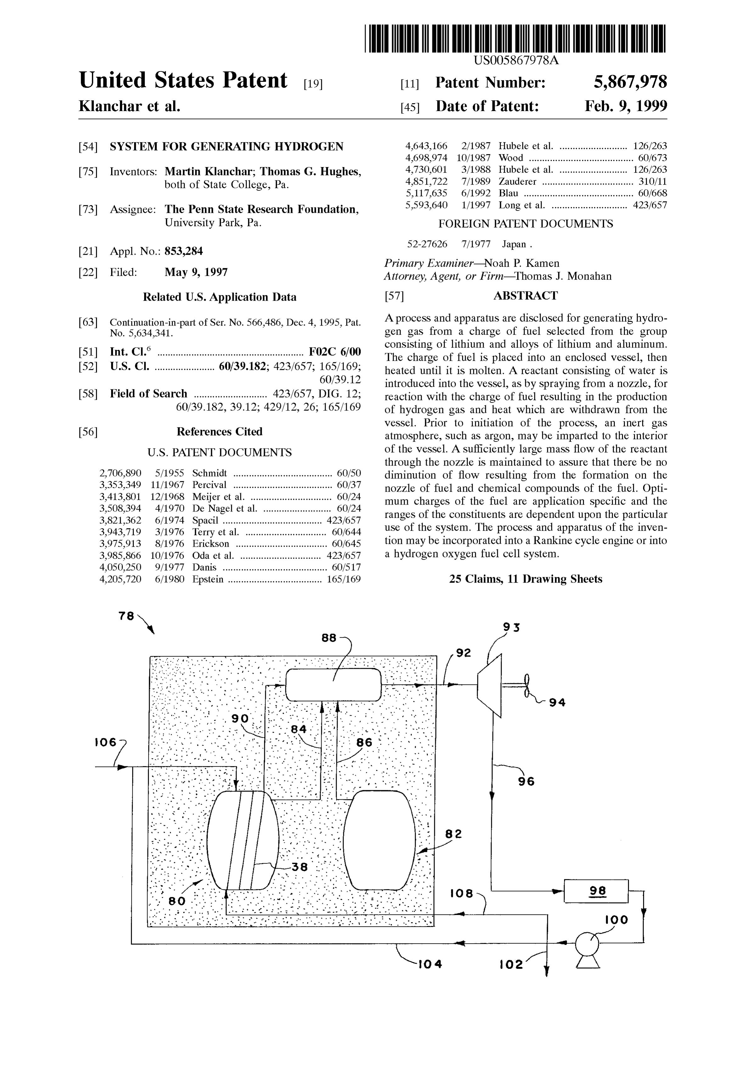
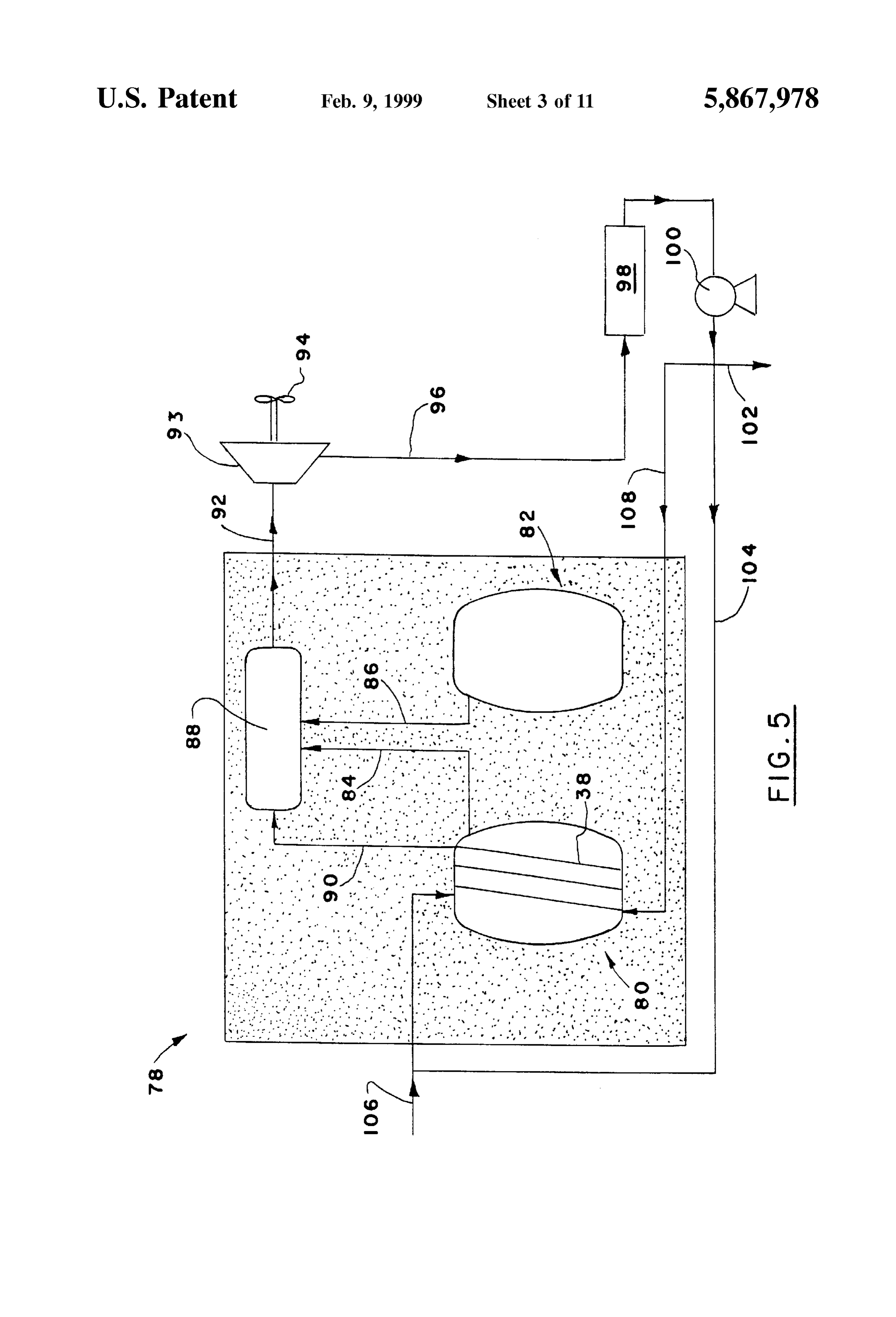
Another object of the present invention is the provision of FIG. 5 is a Schematic representation of a Rankine cycle Such a System which can be utilized in a number of engine utilizing the hydrogen generating reaction vessel of applications, in one instance as a component for a Rankine FIGS. 1 and 2;
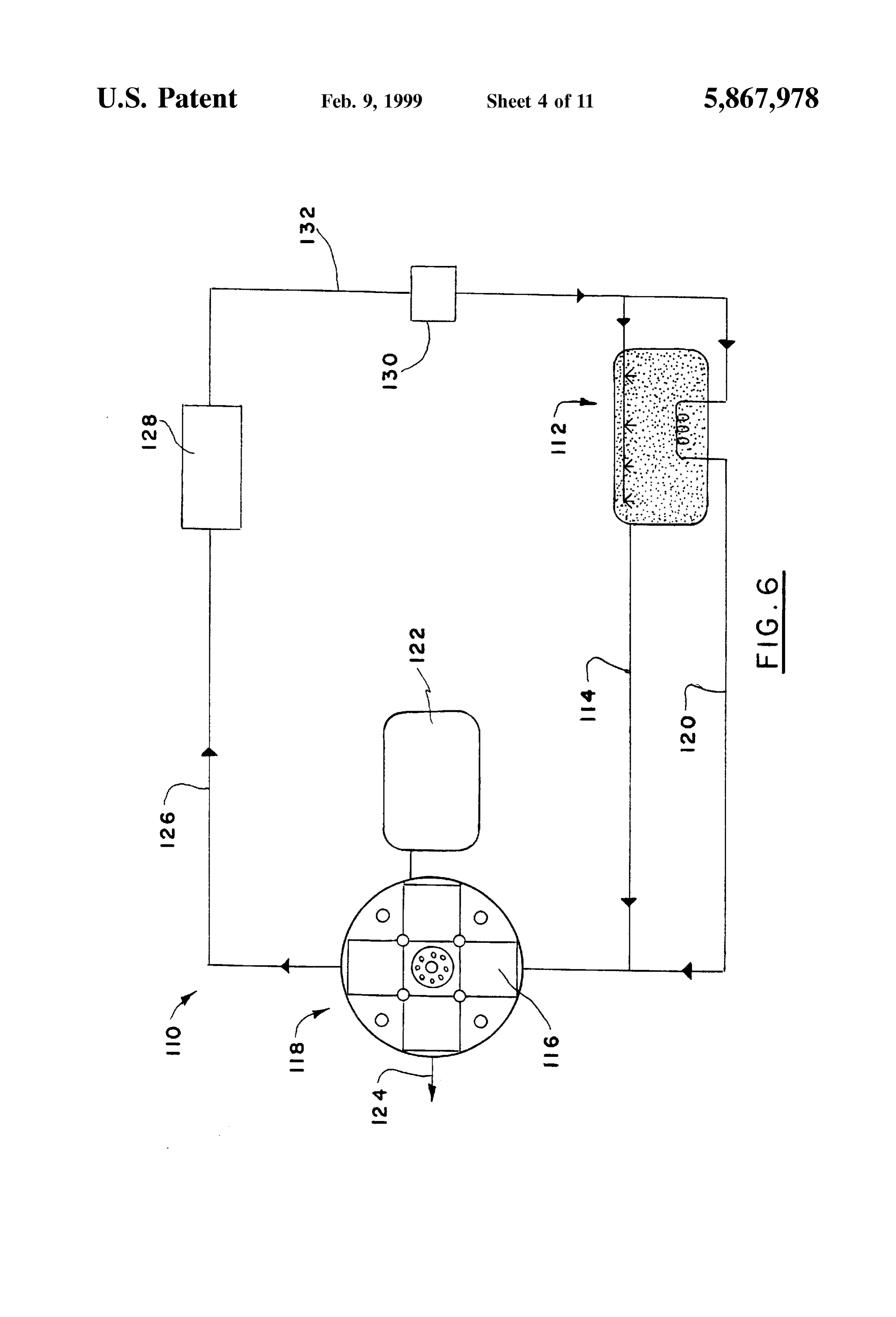
cycle engine and, in another instance, as a component in a FIG. 6 is a Schematic representation of a hydrogen oxygen hydrogen oxygen fuel cell System. fuel cell System utilizing the hydrogen generating reaction Yet a further object of the invention is to provide such a vessel of FIGS. 1 and 2 and
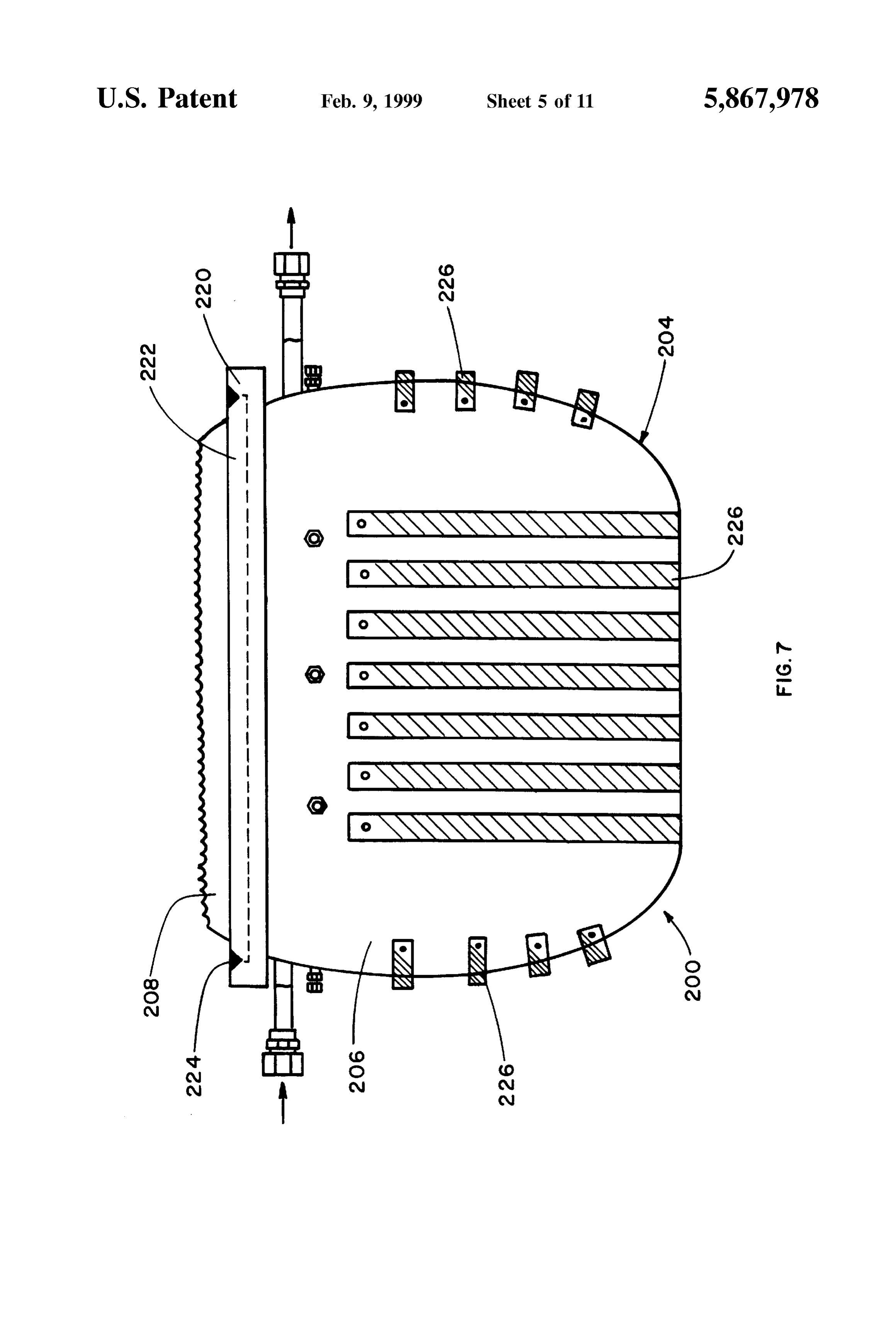
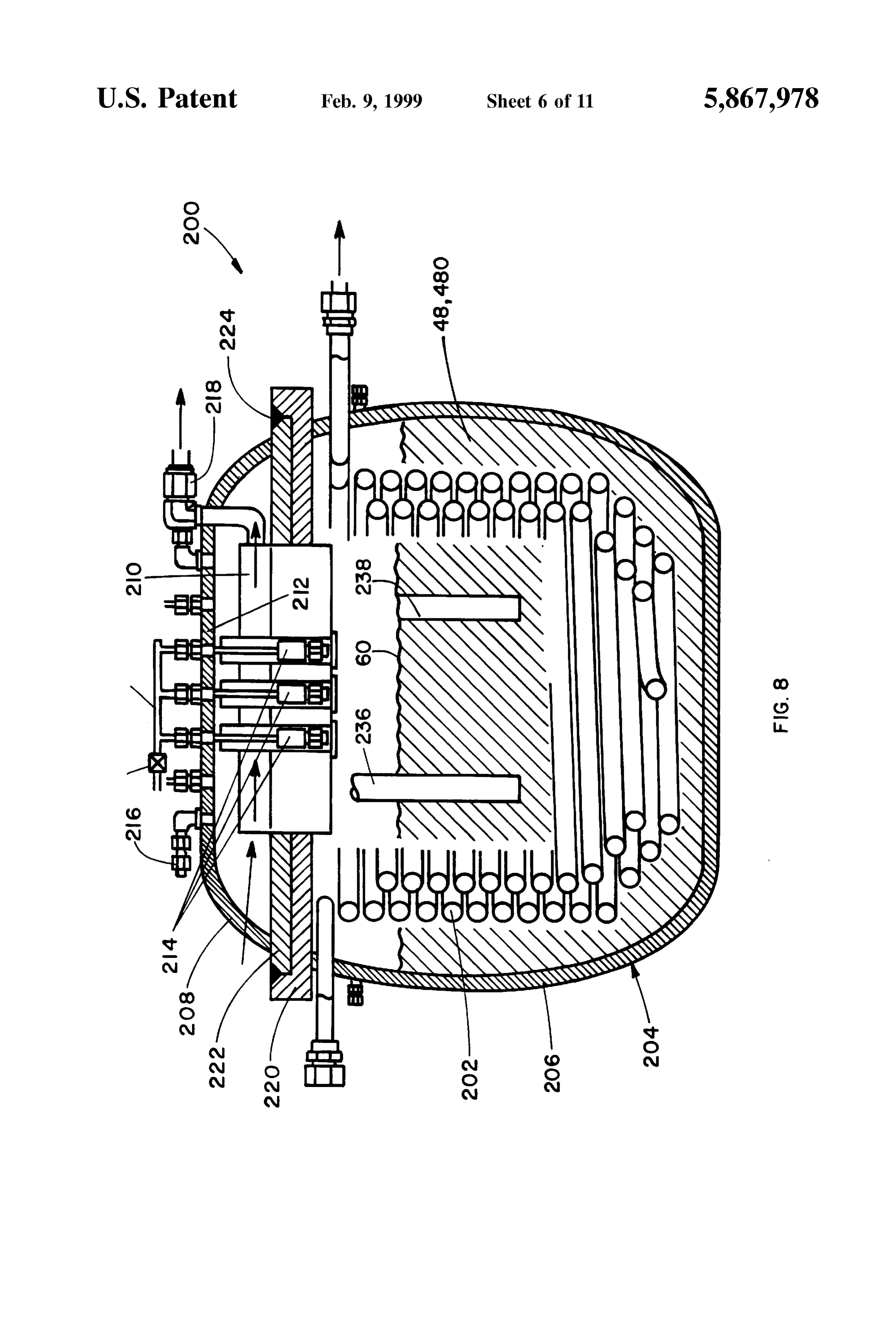
System in which a maximum output of energy is achieved FIG. 7 is a side elevation view illustrating the exterior of from a given Volume of fuel. a modified reaction vessel embodying the present invention; Still another object of the invention is to provide such a FIG. 8 is a cross section view, in elevation, of the modified hydrogen generating System for which, at least in Some reaction vessel illustrated in FIG. 7;
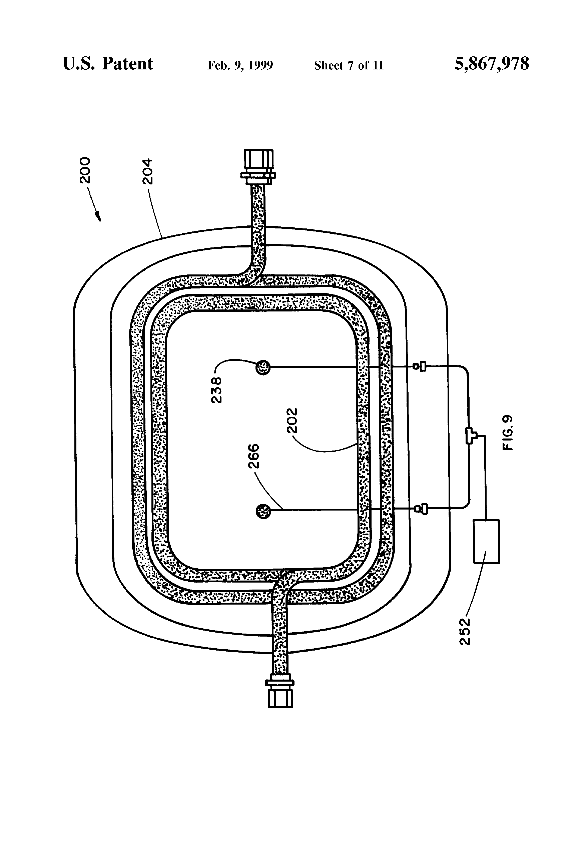
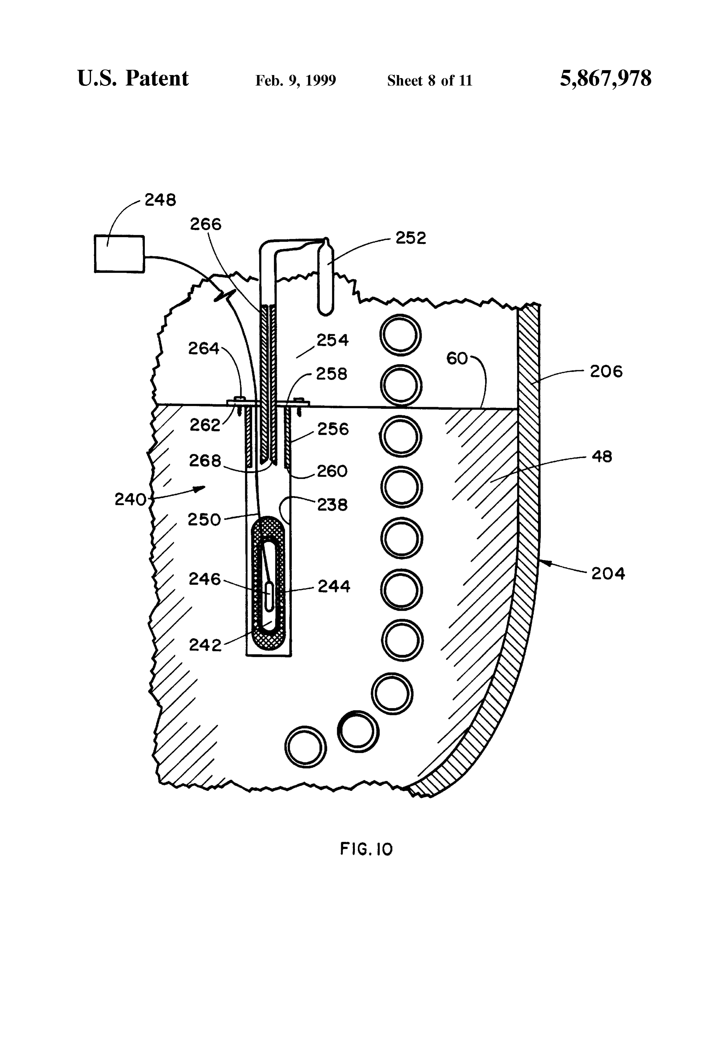
instances, Suitable cooling water tubing is installed So as to FIG. 9 is a top plan view of the main body section of the be completely inside a heavy-duty pressure vessel which is modified reaction vessel generally as illustrated in FIG.8; sized to withstand anticipated preSSure and temperature FIG. 10 is a detail cross section view, in elevation, of a conditions, typically, up to about 550 psia and 2000 F. 15 portion of the modified reaction vessel generally as illus Yet another object of the invention is to provide such a trated in FIG. 8 to illustrate components required for the hydrogen generating System which is operable in two quick-start technique of the invention;
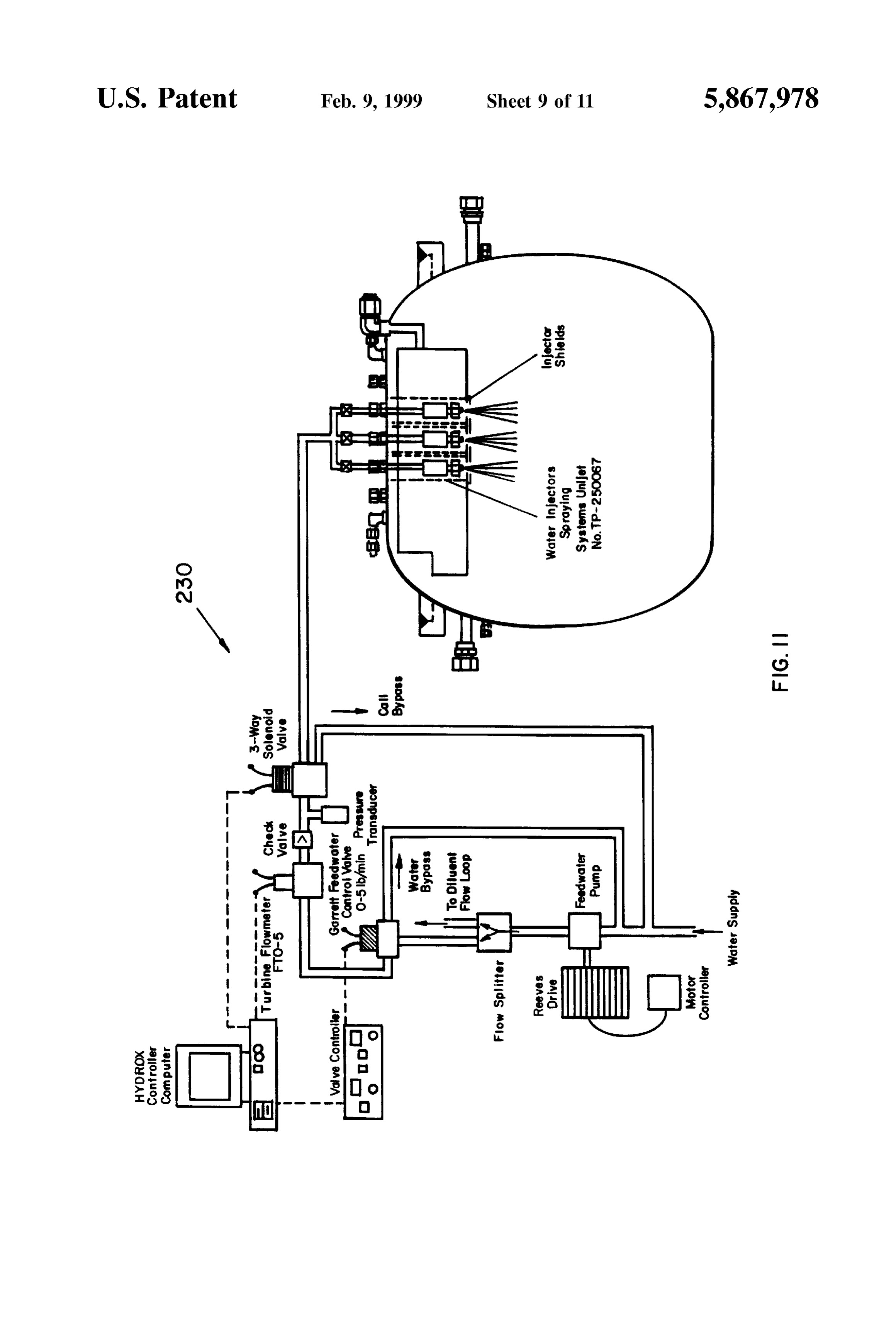
phases, the first phase being a LiH formation Stage where FIG. 11 is a Schematic diagram illustrating the pressure LiH accumulates as an intermediate reaction product in the vessel of FIGS. 7 and 8 and a typical injector water flow fuel bath, producing relatively high heat of reaction per water injected causing LiH to accumulate in the bath along network FIG.
employed in combination there with;
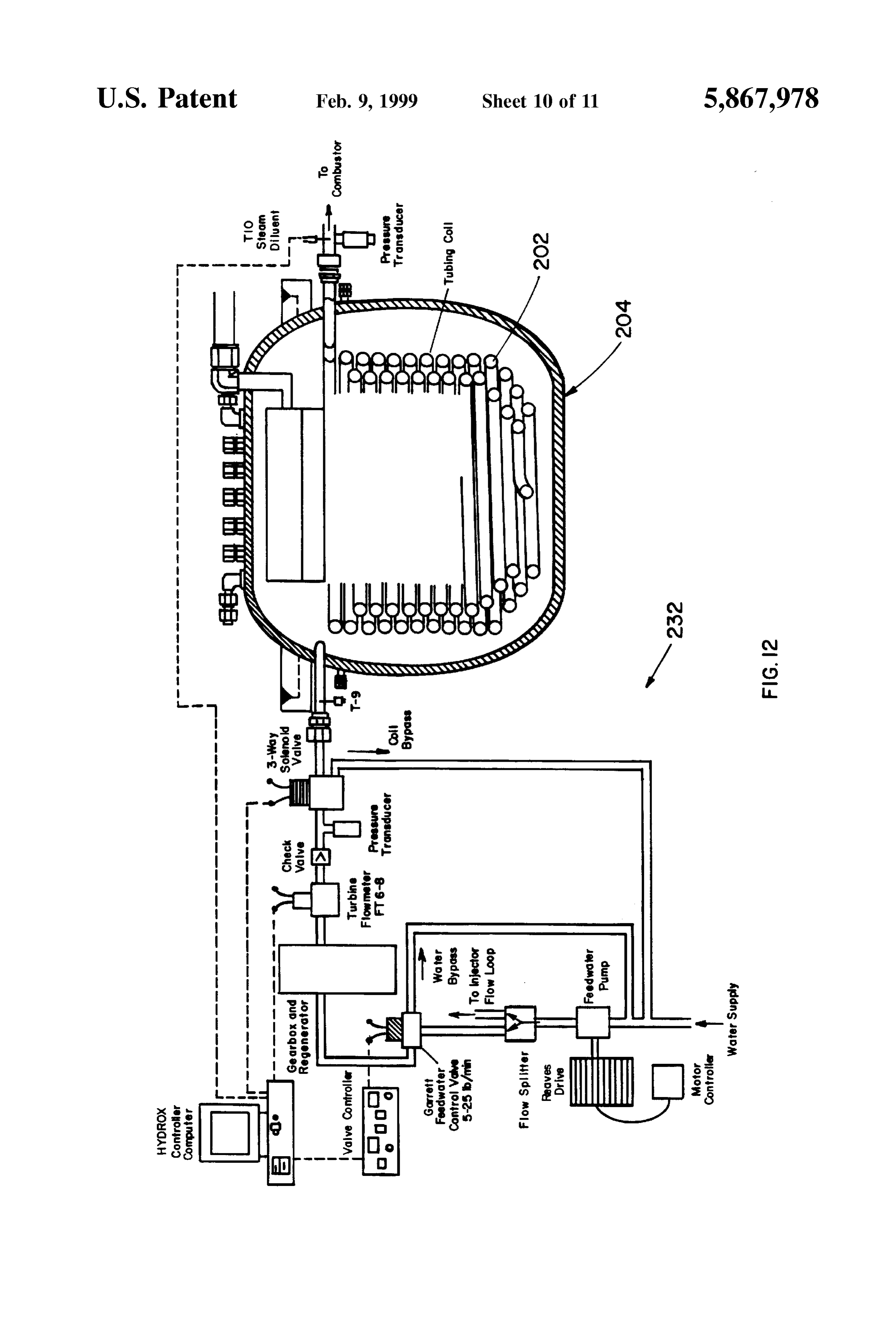
12 is a Schematic diagram illustrating the pressure with unreacted Li, Al, and their metal oxides, the Second phase producing hydrogen gas and allowing the hydrogen vessel of FIGS. 7 and 8 and a typical cooling water flow generator to operate at high pressure, the heat of reaction network employed in combination there with; and being only about half the heat of the first reaction. 25
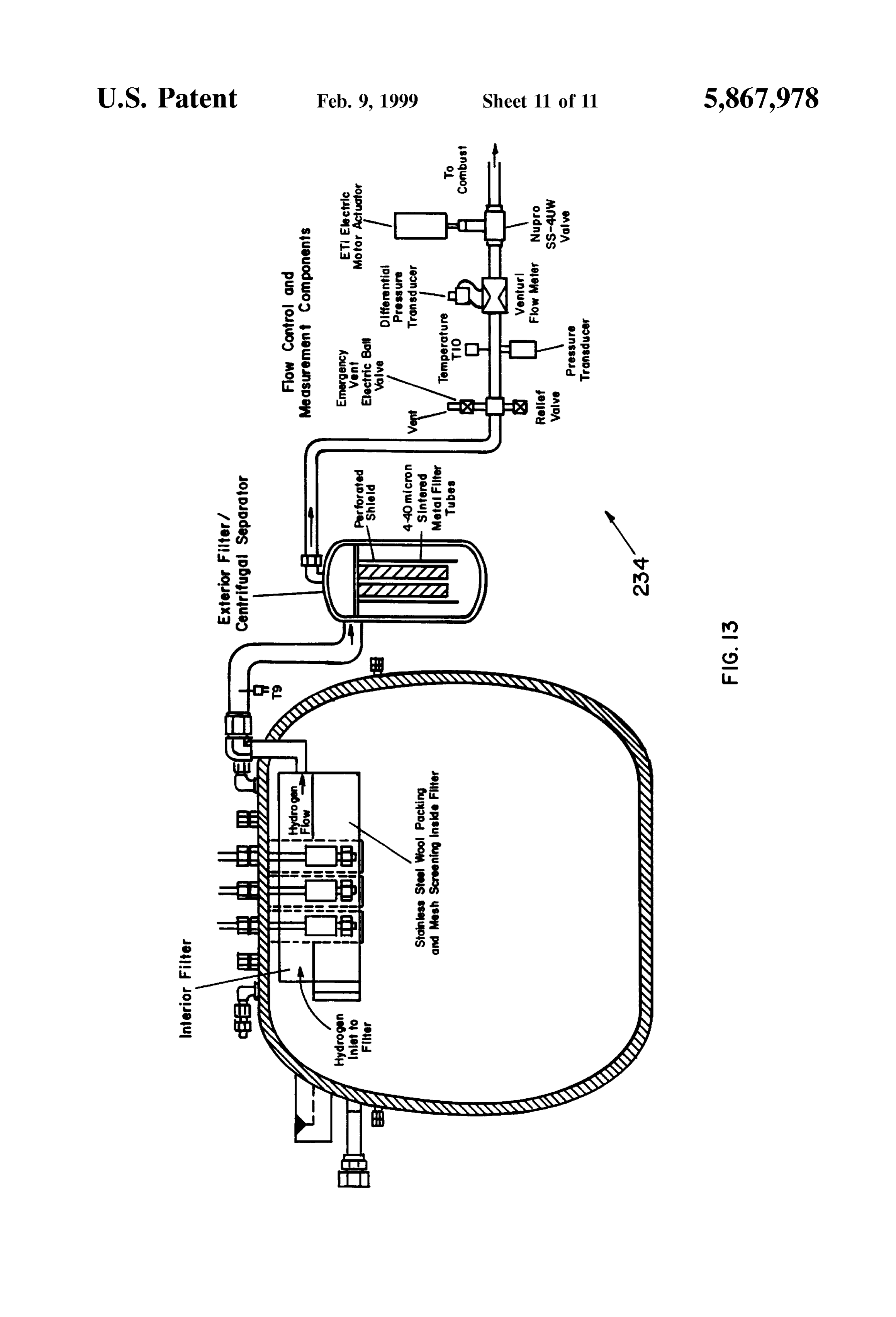
FIG. 13 is a Schematic diagram illustrating the pressure
Still a further object of the invention is to provide such a vessel of FIGS. 7 and 8 and a typical hydrogen flow network employed in combination therewith, including components hydrogen generating System in which the fuel is heated to for filtration, Separation, flow control, and flow measure Starting temperature at a moderate rate by electric band and ment.
Strip heaterS Suitably clamped to the main body Section of the pressure vessel. DETAILED DESCRIPTION OF THE Yet a further object of the invention is to provide such a PREFERRED EMBODIMENT hydrogen generating System in which the fuel is heated to Turn now to FIGS. 1 and 2 which illustrate a reaction Starting temperature using a quick-start technique of the vessel 20 which can be utilized to generate hydrogen gas invention which relies on the combustion of a Small amount of Alclo brand (aluminum powder and KCIO, material) to composed toofthea material
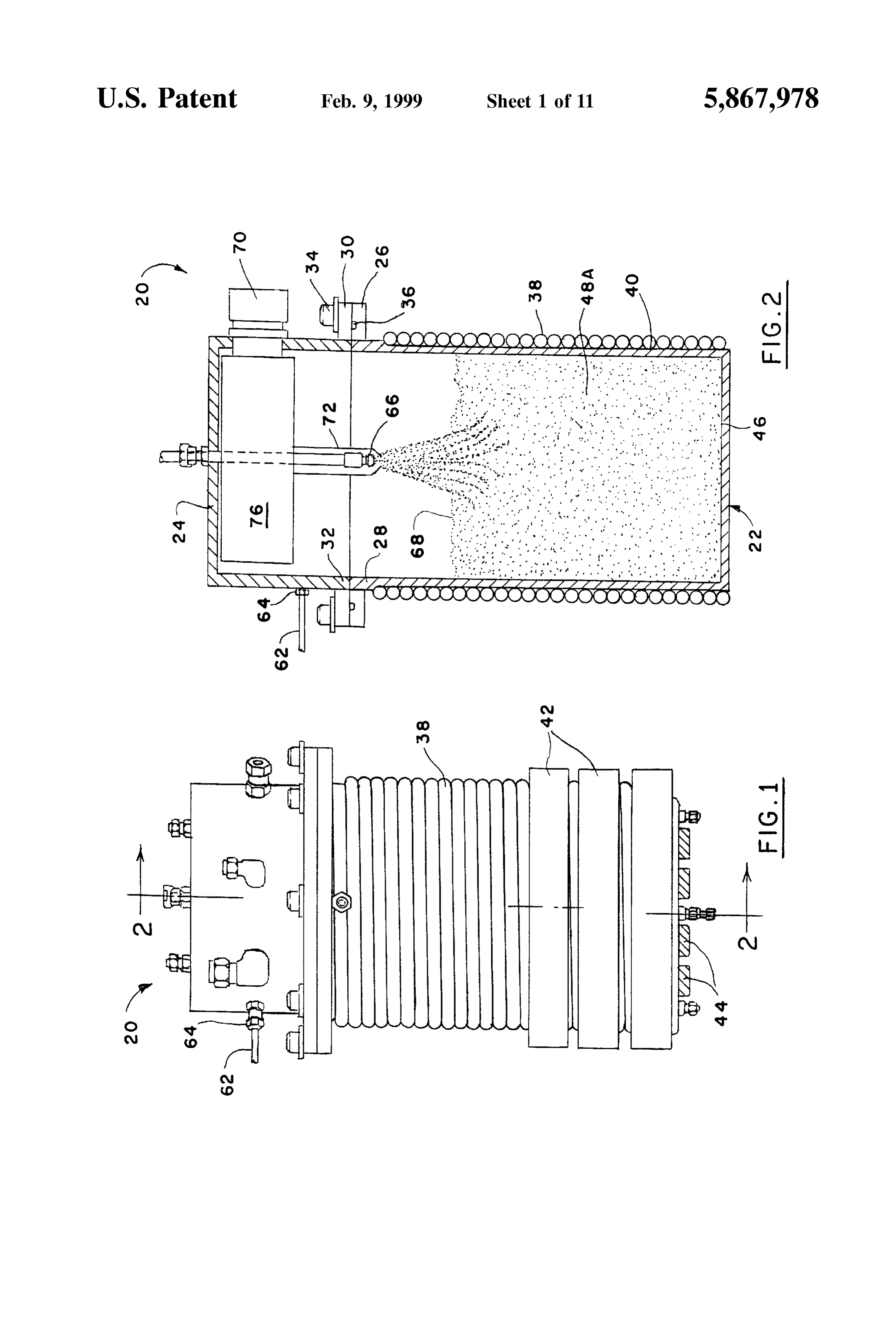
according present invention. The reaction vessel 20 is create a "hot Spot' in each of a plurality of fuel core holes, would not take part in which is relatively inert, that is, any reactions necessary for the that is, upstanding tubular bores formed in the fuel when generation of hydrogen gas. Appropriate materials include Solidified, and then the Simultaneous introduction of SF gas various Stainless Steels and other metallic Superalloys. In any and liquid into that core hole Such that the heat generated event, the reaction vessel 20 comprises a base container 22 from the energetic Li-SF reaction plus the stirring action of 40 which the two-phase (gas and liquid) SFs injection, gradually and a lidis 24 for the purpose of Supporting the reactant materials brings the bulk of the fuel up to the desired Starting tem to Sealingly which matingly connects with the base container enclose the reaction vessel. The base container perature with minimal Splashing. 22 and lid, 24 are preferably generally cylindrical. The Other and further features, advantages, and benefits of the former has an integral annular flange 26 adjacent its upper invention will become apparent in the following description 45 most rim 28 and the lid 24 has an integral annular flange 30 taken in conjunction with the following drawings. It is to be adjacent its lowermost rim 32. The flanges 26, 30 are understood that the foregoing general description and the matingly engageable and can be locked together by a following detailed description are exemplary and explana plurality of circumferentially Spaced fastenerS 34. tory but are not to be restrictive of the invention. The 50 Fluid tight integrity between the flanges 26, 30 is achieved accompanying drawings which are incorporated in and by reason of a circumferentially extending O-ring Seal 36 constitute a part of this invention, illustrate one of the interposed between the flanges.
embodiments of the invention and, together with the description, Serve to explain the principles of the invention SureThevessel reaction vessel 20 thus described is, indeed, a pres defining a single chamber capable of Safely in general terms. Like numerals refer to like parts throughout containing reactions which develop operating preSSures in the disclosure. 55 excess of 100 psia.
BRIEF DESCRIPTION OF THE DRAWINGS Cooling plumbing is provided in the form of Spiral tubing 38 which envelopes the peripheral external surface 40 of the
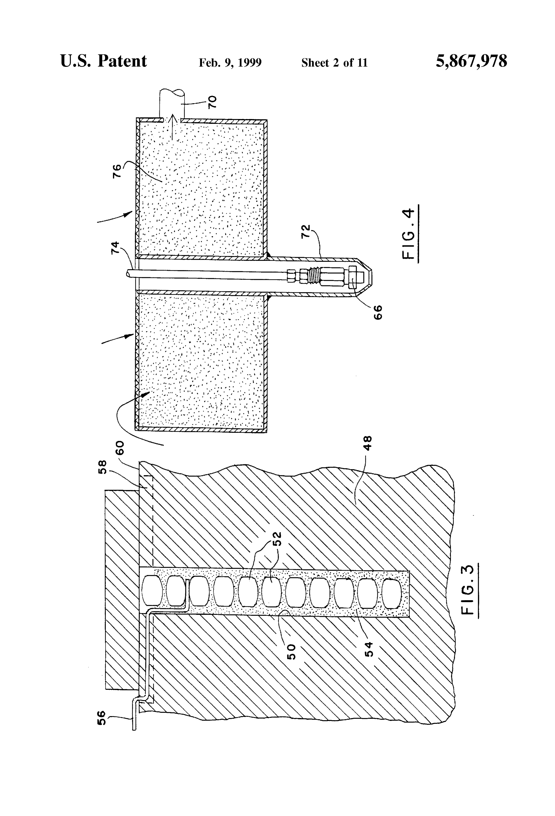
FIG. 1 is a Side elevation View illustrating a reaction base container 22. It is preferably welded into place and vessel embodying the present invention; 60 enables flow of cooling water at a rapid rate from an ambient FIG. 2 is a croSS Section view, in elevation, taken gener Source from the uppermost regions of the base container to ally along line 2-2 in FIG. 1; its lowermost regions.
FIG. 3 is a detail cross section view of a pyrotechnic The reaction vessel 20 also has provision for heating its arrangement for heating fuel in the reaction vessel of FIGS. interior. This may be achieved in a number of different ways. 1 and 2; 65 For example, a propane burner (not shown) may be posi FIG. 4 is a detail cross section view to provide more detail tioned beneath the base container 22 and ignited when of a component illustrated in FIG. 2; appropriate. In another instance, electrical band heaters 42,
Page 16
44 may be utilized. In this instance, a plurality of cylindrical vessel 20 by means of water flow through the spiral tubing band heaters 42 may be Suitably mounted on the peripheral 38, and exhaust tubing 70 is employed for withdrawing the exterior of the base container 22 at its lowermost regions. hydrogen gas from the interior of the reaction vessel 20. Similarly, strip heaters 44 are suitably mounted to a bottom Because of the intense heat within the reaction vessel, as wall 46 of the base container 22. well as the Violent agitation caused by the reaction, a Yet another manner of heating, as generally illustrated in protective cylindrical shield 72, preferably made of stainless FIG. 3 may be employed either by itself or in conjunction steel, Surrounds a water inlet conduit 74 and the nozzle 66 with one of the heating techniques just described. In this to prevent their degradation.
instance, Solid fuel 48, typically in block form, placed in the Since the reaction within the vessel 20 is vigorous and base container 22, is provided with its own pyrotechnic combustion-like, the hydrogen gas So produced leaves the devices which provide considerable amounts of heat in a vessel via the exhaust tubing 70 at a very high velocity. This nearly instantaneous manner. In this instance, a plurality of causes entrainment of unreacted fuel and Solid products, for core holes 50 are formed into the block of the fuel 48. A example, oxides and hydroxides of lithium and aluminum plurality of Alclo brand (a mixture of aluminum and potas 15 (in the event aluminum is in the starting fuel) in the gas sium perchlorate) pellets 52 are inserted into each core hole stream which must be removed before it leaves the vessel. For this reason, it is important to provide a filter 76 which 50. The pellets are spaced apart and Supported in a bed or is integral with the cylindrical shield 72 and is interposed matrix 54 of thermite, also known as a mixture of aluminum and copper oxide. between the interior of the vessel and the exhaust tubing 70. An igniter wire 56 extends from a region beyond the fuel The hydrogen gas which exits the reaction vessel 20 is thereby assured of having a high level of purity.
block 48 and, indeed, extends through the interface between The reaction vessel 20 for generating hydrogen can be the lid 24 and the base container 22 to a location outside of reaction vessel 20. An innermost end of the igniter wire 56 example, itinmaya variety employed of Systems. In one instance, for have application in a Rankine Steam cycle is preferably positioned between a pair of the pellets 52 power plant 78 used for underwater propulsion purposes. within the bed 54 of thermite. A vent groove 58 may be 25 Such a system is illustrated provided at an uppermost surface 60 of the fuel block 48 in hydrogen generator 80 generallyin ofFIG. 5. It comprises a order to vent the combustion products of the pyrotechnic reaction vessel 20 and an oxygen generator 82 whichofmay the construction the charge just described. be, for example, generally of the construction disclosed in The block of fuel 48, for purposes of the invention, is commonly assigned copending application Ser. No. 08/132, Selected from the group consisting of lithium, and alloys of 021 and filed Oct. 5, 1993, now U.S. Pat. No. 5,376,352. As lithium and aluminum, and alloys of lithium and aluminum indicated in FIG. 5, hydrogen gas from the hydrogen gen and lithium hydride, and alloys of lithium and lithium erator 80 and oxygen gas from the oxygen generator 82 flow hydride. In each instance, a wide range of compositions of via lines 84, 86, respectively, to a burner 88, along with low the components of the fuel may be utilized when other than temperature steam which travels via a line 90 from the spiral 100% lithium. The lithium and lithium-alloy fuel mixtures provide exceptional energy density in terms of hydrogen and 35 tubinggas are 38 in the burner 88. The hydrogen gas and the oxygen combusted to generate Super heated Steam which heat production. The exact composition of the alloy fuel is travels via determined according to the hydrogen and heat generation example, tolinedrive 92 to a turbine 93 which produces power, for a shaft and propeller 94. Exhaust lower requirements of the Rankine or hydrogen oxygen fuel cell energy steam is directed from the turbine 93 via line 96 to Systems. 40 a condenser 98 which operates to change its State into water. Prior to operation of the reaction vessel 20, it may be A feed water pump 100 operates to cycle the water through desirable to purge the interior of the vessel, after it is Sealed, the power plant. ExceSS Water from the feed water pump with an inert gas for the purpose of removing oxygen which, may be dumped via a line 102 while reactant water may be if present, would have an undesirable effect on the reaction. delivered to the hydrogen generator 80 via a line 104 along For this purpose, a line 62 is illustrated in FIGS. 1 and 2 45 with Starting water from a line 106, and cooling water may connected via a fitting 64 to the lid 24 for introducing a be delivered to the spiral tubing 38 via a line 108. preSSurized inert gas Such as argon to the interior of the In another instance, as illustrated in FIG. 6, a hydrogen reaction vessel 20. Flow of the inert gas is not continuous. oxygen fuel cell System 110 may utilize a hydrogen genera When water injection into the vessel is begun, flow of the tor 112 which is substantially of the construction of the inert gas is terminated. 50 reaction vessel 20. In this instance, hydrogen gas generated While purging continues, the heating operation begins within the generator 112 is delivered via a line 114 to a using any, or any combination, of the heating mechanisms plurality of stacks 116 within a solid oxide fuel cell 118. already described, or any other manner of heating which Water heated by the hydrogen generator 112 may also be may be Suitable for the purpose. Heating continues until the delivered to the stacks 116 via a line 120 to wet the Solid fuel is molten which occurs at approximately 600 F. At this 55 oxide electrodes to maintain ionic conductivity. The Steam point, reactant consisting of water is introduced into the produced in the hydrogen generator is delivered to the fuel vessel via a nozzle 66 directed at a Surface 68 of the now cell stacks where it wets the Solid oxide electrodes to molten fuel 48A as illustrated in FIG. 2. maintain ionic conductivity. An oxygen generator 122, Indeed, the nozzle 66 is so directed at the Surface of the which may be Similar to the oxygen generator 82 and of the molten fuel 48A that the water spray penetrates the surface 60 type disclosed in U.S. Pat. No. 5,376,352, mentioned above, and causes agitation of the mass of the molten fuel. The serves to provide oxygen gas to the fuel cell 118. The fuel reaction of water and fuel results in the production of cell 118 is operable to generate electricity and to deliver it hydrogen gas and heat. Because the reaction between the externally as Schematically represented by an arrow 124. fuel and the reactant, or water, is an exothermic one, once Water produced as a result of the electrochemical reaction of the reaction has begun, it is no longer necessary to continue 65 the hydrogen gas and oxygen gas is withdrawn from the fuel with the operation of the heaters 42, 44 and their operation cell 118 and delivered via a line 126 to a heat exchanger 128 is then discontinued. Heat is withdrawn from the reaction which reduces the temperature of the water to an ambient
Page 17
level. A feed water pump 130 in a line 132 is operable for Typically 15 heaters are mounted around the main body cycling the water through the fuel cell system 110. section to provide approximately 13,000 watts of heater A further improved hydrogen generator 200 is illustrated power. The heaters 226 are also used to heat the preSSure in FIGS. 7-13 and represents the latest and largest of a series vessel or reactor during fuel preparation, that is, when the of reactors developed to chemically Supply hydrogen gas fuel is initially introduced into the main body section of the and heat. One typical application of the generator 200 is as preSSure vessel. More recently, however, the heating proceSS a component of an underwater closed cycle thermal propul has been initiated using a chemical combustion quick-start Sion powerplant and its design, function and test perfor procedure which will be described below. mance will be described in the following Section as a means The improved hydrogen generator 200 not only includes of detailing the latest technology and issues regarding the pressure vessel 2054 itself, but also important support chemical hydrogen generation. Systems outside the pressure vessel. These Systems, pre While still a batch-type reactor, the design of the sented in FIGS. 11, 12, and 13 include supply loops for both improved hydrogen generator 200 is slightly different than reaction and cooling water, components for hydrogen flow prior pilot-Scale vessels in that the boiler cooling water 15 measurement and product Separation, and all the instrumen tubing was no longer part of the actual vessel Structure in all tation used to monitor and control operation. The design and instances as earlier described. Instead, at least in Some hardware of these Systems may vary slightly between uses, instances, Suitable cooling water tubing 202 is installed So as but typical Schematic diagrams of an injector water flow to be completely inside a heavy-duty pressure vessel 204, loop 230 cooling water loop 232, and hydrogen flow plumb which is sized to withstand anticipated pressure and tem ing 234 are outlined in FIGS. 11, 12 and 13, respectively. perature conditions, typically up to about 550 psia and 2000 The general chemistry for the case of the lithium-water F. reaction at 2000 F. is typically expressed by the relation The general operating and design requirements of the ship:
improved System include the following considerations:
Supply a controllable flow of clean hydrogen gas, pro 25 duced from the reaction of molten alloy fuel with while that of an alloy fuel containing 92 mole percent Water, lithium and 8 mole percent aluminum is expressed by the Provide a means of removing reaction heat and generating relationship:
Steam,
Provide Storage and containment of the alloy fuel and reaction products,
Operate at pressures up to 550 psia and temperatures up Equations (1) and (2) represent the overall or final reac to 2000 F; tion chemistry. AS will be explained below, intermediate Provide a means of “quick Starting the reactor, that is, reactions and other products will form because of the initially bringing the fuel up to reaction (molten) tem 35 bath-type reaction process, that is, as water is introduced into an excess of fuel.
perature in a short period of time; and
Mount and operate inside the condenser shell Section of Both equilibrium modeling and experimental perfor mance of the reaction process have revealed another diffi the test vehicle for the underwater closed cycle thermal culty associated propulsion powerplant. with application of pure lithium or 40 aluminum-lithium fuels. Reaction chemistry, and thus
The pressure vessel 204 constructed for this application includes two primary Sections. Viewing FIG. 8, a larger main hydrogen generation, are dependent on reactor operating body section 206 accommodates the Zone in which the preSSure, at least during the initial part of the process. This reaction is to take place, the cooling water tubing 202, and preSSure effect does not initially allow the reactor to operate the entire storage volume of the fuel 48, 48A. A smaller top 45 of at elevated preSSure, which precludes an immediate Supply lid section 208 contains an internal filter 210, mounts 212 for hydrogen. In one typical application of the hydrogen water injectors 214, fittings 216 for instrumentation closed cycle generator of the invention, for example, in an underwater connections, and a hydrogen outlet 218. The main body and for the hydrogen thermal propulsion powerplant, it is essential top lid sections 206, 208 both contain flanges 220, 222, generator to operate at elevated preSSure respectively, that are welded together, as indicated at 224, 50 (up to about 550 psia), because of the high downstream during the final assembly to Seal the pressure vessel or operating pressures (about 550 psia) of the H-O com reactor 204. bustor 88 and turbine 93, for example. Some of the general Specifications of the resulting The inability of the reactor to pressurize initially is due to improved hydrogen generator 200 are listed below; they are the formation of LiH in the fuel bath instead of free not intended to be restrictive of the invention but are related hydrogen. The inventors have come to realize, however, that only for purposes of describing one System which operates 55 this represents a transient Situation as the fuel bath eventu according to the invention: ally becomes Saturated with LiH, given adequate water Overall shape and size: Cylinder with torispherical end erator addition. When LiH Saturation occurs, the hydrogen gen caps; 20" diameter by 23" long pressurizes and provides a controllable amount of hydrogen gas.
Internal Coil: 100' of % “ODx0.065” wall tubing 60 AS hydrogen generation testing progressed, it became Void volume of Main Body: 2.42 ft readily apparent that a Single Straightforward reaction equa Total Weight (without fuel): 425 pounds tion (as in equations (1) or (2)) would be insufficient for Typical Fuel Weight: 55–75 pounds modeling the actual proceSS over the entire operating period. For earlier prototype testing of the hydrogen generator Testing showed that the reaction of lithium with water 200, electric band and strip heaters 226 (FIG. 7) were 65 produced products of LiH, LiOH, or LiO in varying clamped on the outside of the main body section 206 shell amounts, rather than the common assumption of just LiO. to heat the fuel to a starting temperature of about 600 F. Additionally, exact product formation depended on pressure,
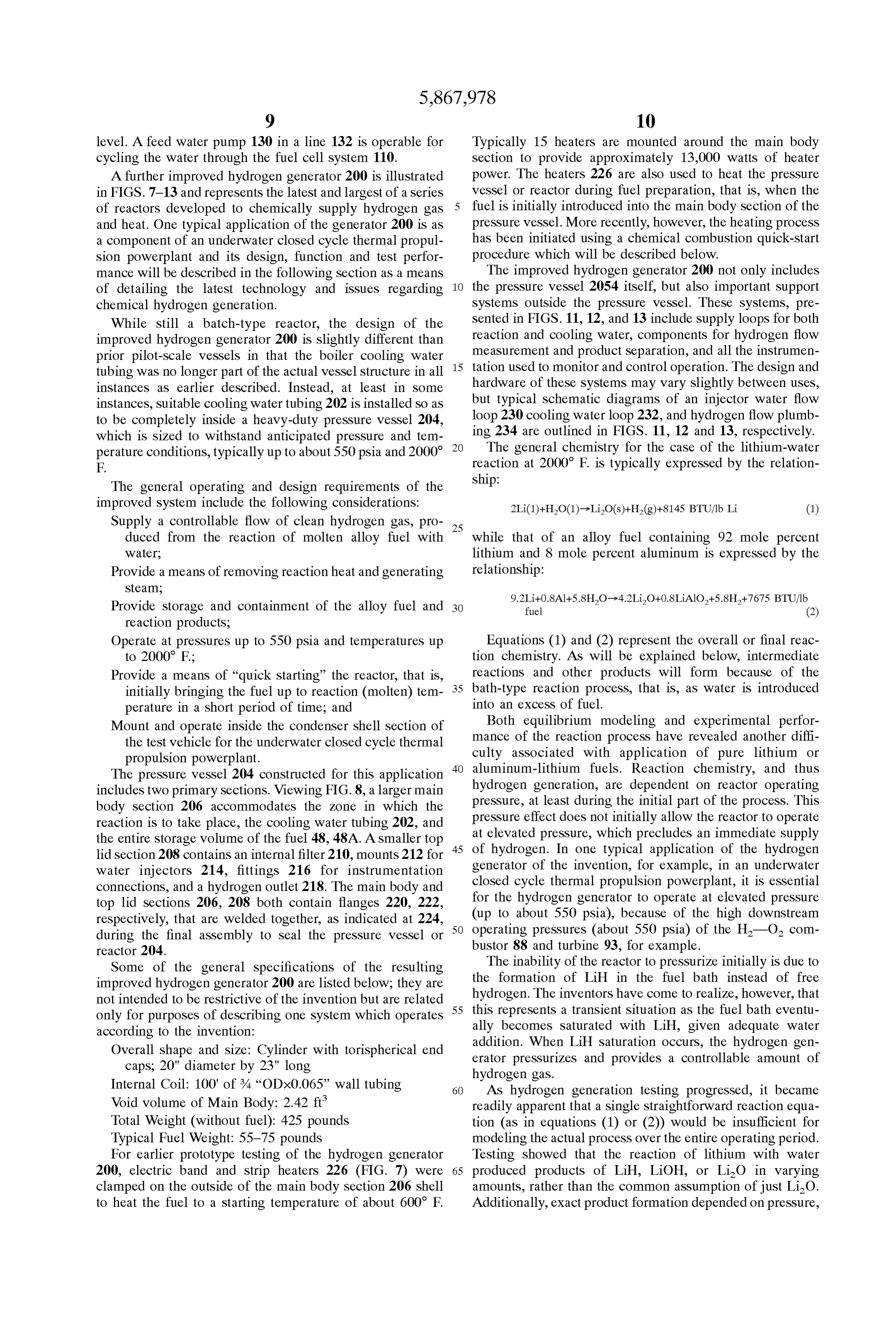
Page 18
temperature and Surrounding reaction environment and concentrations properties that varied considerably over the and reaction period.
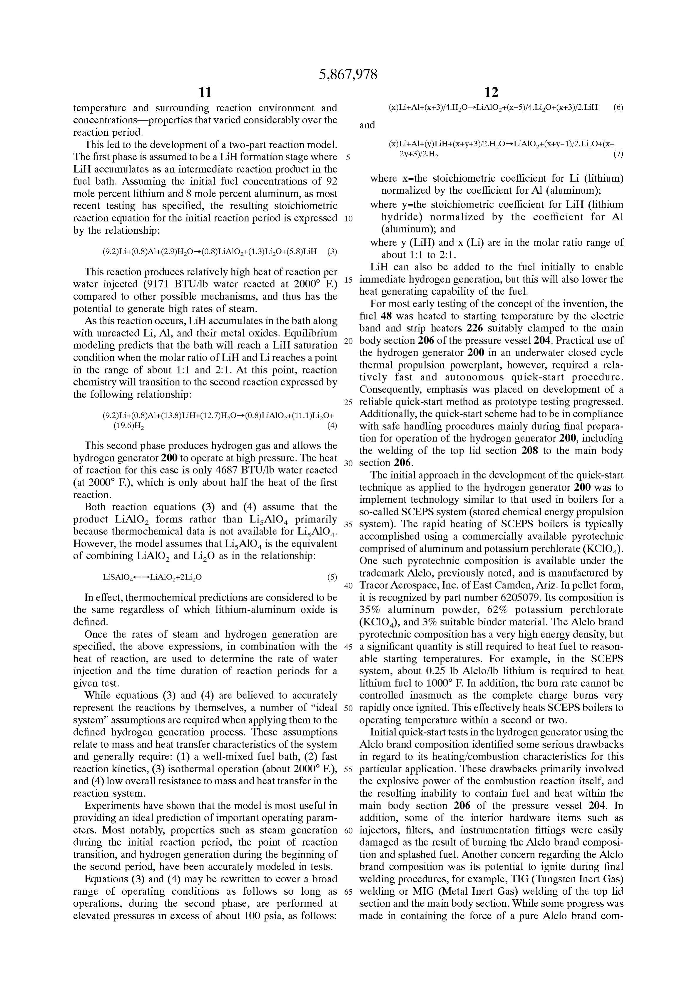
This led to the development of a two-part reaction model.
The first phase is assumed to be a LiH formation Stage where
LiH accumulates as an intermediate reaction product in the fuel bath. Assuming the initial fuel concentrations of 92 where X=the stoichiometric coefficient for Li (lithium) mole percent lithium and 8 mole percent aluminum, as most normalized by the coefficient for Al (aluminum); recent testing has specified, the resulting Stoichiometric where y=the stoichiometric coefficient for LiH (lithium reaction equation for the initial reaction period is expressed 1O hydride) normalized by the coefficient for Al by the relationship: (aluminum); and where y (LiH) and X (Li) are in the molar ratio range of
This reaction produces relatively high heat of reaction per 15 LiH can also be added to the fuel initially to enable water injected (9171 BTU/lb water reacted at 2000 F) immediate heat hydrogen generation, but this will also lower the generating capability of the fuel.
compared to other possible mechanisms, and thus has the For most early testing of the concept of the invention, the potential to generate high rates of Steam.
AS this reaction occurs, LiH accumulates in the bath along band fuel 48 was heated to starting temperature by the electric with unreacted Li, Al, and their metal oxides. Equilibrium body section and Strip heaters 226 Suitably clamped to the main modeling predicts that the bath will reach a LiH Saturation the hydrogen206 of the pressure vessel 204. Practical use of generator 200 in an underwater closed cycle condition when the molar ratio of LiH and Li reaches a point thermal propulsion powerplant, in the range of about 1:1 and 2:1. At this point, reaction tively fast and autonomous however, required a rela quick-start procedure.
chemistry will transition to the Second reaction expressed by Consequently, emphasis was placed on development of a the following relationship: 25 reliable quick-start method as prototype testing progressed. (9.2)Li+(0.8)Al--(13.8)LiH+(12.7)HO->(0.8)LiAlO+(11.1)LiO+ Additionally, the quick-start Scheme had to be in compliance (19.6)H, (4) with Safe handling procedures mainly during final prepara tion for operation of the hydrogen generator 200, including
This Second phase produces hydrogen gas and allows the the welding of the top lid section 208 to the main body hydrogen generator 200 to operate at high pressure. The heat Section 206.
of reaction for this case is only 4687 BTU/lb water reacted The initial approach in the development of the quick-start (at 2000 F), which is only about half the heat of the first technique as applied to the hydrogen generator 200 was to reaction.
implement technology similar to that used in boilers for a
Both reaction equations (3) and (4) assume that the so-called SCEPS system (stored chemical energy propulsion product LiAlO forms rather than LisalO primarily 35 system). The rapid heating of SCEPS boilers is typically because thermochemical data is not available for LisalO. accomplished using a commercially available pyrotechnic However, the model assumes that LisalO is the equivalent comprised of aluminum and potassium perchlorate (KClO). of combining LiAlO and LiO as in the relationship: One Such pyrotechnic composition is available under the LiSAIO-->LiAlO+2LiO (5) trademark Alclo, previously noted, and is manufactured by 40 Tracor Aerospace, Inc. of East Camden, Ariz. In pellet form,
In effect, thermochemical predictions are considered to be it is recognized by part number 6205079. Its composition is the same regardless of which lithium-aluminum oxide is 35% aluminum powder, 62% potassium perchlorate defined. (KClO), and 3% suitable binder material. The Alclo brand Once the rates of Steam and hydrogen generation are pyrotechnic composition has a very high energy density, but Specified, the above expressions, in combination with the 45 a significant quantity is still required to heat fuel to reason heat of reaction, are used to determine the rate of water able starting temperatures. For example, in the SCEPS injection and the time duration of reaction periods for a system, about 0.25 lb Alclo/lb lithium is required to heat given test. lithium fuel to 1000 F. In addition, the burn rate cannot be While equations (3) and (4) are believed to accurately controlled inasmuch as the complete charge burns very represent the reactions by themselves, a number of "ideal 50 rapidly once ignited. This effectively heats SCEPS boilers to System' assumptions are required when applying them to the operating temperature within a Second or two. defined hydrogen generation process. These assumptions Initial quick-start tests in the hydrogen generator using the relate to mass and heat transfer characteristics of the System Alclo brand composition identified Some Serious drawbacks and generally require: (1) a well-mixed fuel bath, (2) fast in regard to its heating/combustion characteristics for this reaction kinetics, (3) isothermal operation (about 2000 F), 55 particular application. These drawbacks primarily involved and (4) low overall resistance to mass and heat transfer in the the explosive power of the combustion reaction itself, and reaction System. the resulting inability to contain fuel and heat within the Experiments have shown that the model is most useful in main body section 206 of the pressure vessel 204. In providing an ideal prediction of important operating param addition, Some of the interior hardware items. Such as eters. Most notably, properties Such as Steam generation 60 injectors, filters, and instrumentation fittings were easily during the initial reaction period, the point of reaction damaged as the result of burning the Alclo brand composi transition, and hydrogen generation during the beginning of tion and Splashed fuel. Another concern regarding the Alclo the Second period, have been accurately modeled in tests. brand composition was its potential to ignite during final Equations (3) and (4) may be rewritten to cover a broad welding procedures, for example, TIG (Tungsten Inert Gas) range of operating conditions as follows So long as 65 welding or MIG (Metal Inert Gas) welding of the top lid operations, during the Second phase, are performed at Section and the main body Section. While Some progreSS was elevated pressures in excess of about 100 psia, as follows: made in containing the force of a pure Alclo brand com
Page 19
bustion quick-start procedure, an alternative heating method upper surface 60 of the charge of fuel 48 before the heating was adopted, which Significantly reduced the amount of operation commences. A conduit 266 extends between the Alclo composition required and greatly simplified initial fuel Source 252 of SF gas and liquid and terminates at a nozzle preparation. 268 for directing the SF gas and liquid onto the hot spot at Turn now to FIGS. 8, 9, and 10 for a description of the the critical flow rate, that is, issuing forth at the Speed of preparation for and operation of the quick-start procedure Sound. The conduit 266 is fixed to the cover 262 so that the for initiating operation of the hydrogen generator 200. With nozzle 268 is firmly held in position within the upstanding the main body section 206 covered, either with the top lid tubular bore 238.
Section 208 or in Some other manner, but not sealed, molten Thus, the quick-start technique of the invention relies on lithium (at about 500 F) is poured into the main body the combustion of a small amount of the Alclo brand Section. Simultaneously, argon or other Suitable inert gas is material to create a "hot Spot' in each of the fuel core holes, pumped into the pressure vessel 204 in the manner previ that is, in the upstanding tubular bores 238, and then the ously described So as to maintain an inert atmosphere in the Simultaneous introduction of SF gas and liquid into that preSSure vessel. A typical charge of lithium is about 50 core hole. The heat generated from the energetic LI-SF pounds although that amount is exemplary and not intended 15 reaction (about 20,000 BTU/lb Li) plus the stirring action of to restrict the invention. The lithium is then allowed to cool the two-phase (gas and liquid) SF injection, gradually to room temperature and solidify and the pressure vessel 204 brings the bulk of the fuel 48, 48A up to the desired starting is Sealed under the argon atmosphere. Thereafter, using the temperature with minimal Splashing. heaters 226, the pressure vessel 204 is heated and the The design and location of the quick-start core holes or temperature of the lithium is raised to between about 500 F. upstanding tubular bores 238 are shown in FIGS. 8 and 9. and 600 F. A mixing head (not shown) is lowered into the Two bores 238 are illustrated being installed along the molten lithium and Stirring begun. Slowly, Solid aluminum centerline of the fuel bath (FIG. 9). These are then loaded pellets (approximately -7+40 mesh, of tear drop shape) are with a Small amount of pyrotechnic Start charge comprised added. Of the total amount of alloy fuel prepared, the primarily of the electric match igniter 246, one crushed aluminum concentration is about 25% to about 45% by 25 Alclo brand tablet (about 0.75 gr.). The conduit 266 may be, weight. Stirring of the alloy mixture is continued even as it for example, a narrow-bore '4" stainless steel tube which is heated to 900 F. for a period of one to two hours. introduces SF flow about 1" below the fuel Surface 60 when Thereafter, 34" diameter upright stainless steel rods 236 the Start charge is ignited. The SF is Stored as a liquid at its (only one is illustrated in FIG. 8) are suitably positioned in vapor pressure (300 psia at 60 F) at the source 252, in a the molten fuel So as to form at least a pair of upstanding vessel outside the pressure vessel 204, and its flow rate is tubular bores 238. The pressure vessel 204 is cooled to room roughly controlled by the length (and corresponding pres temperature by circulating cool water from the cooling water Sure drop) of the narrow-bore tubing, conduit 266, leading loop 232 (FIG. 12) through the cooling water tubing 202. into the bore 238.
When the fuel is solidified, the upright stainless steel rods Uniform fuel bath temperatures of 1200°-1400° F have 236 are removed from the Solidified fuel. 35 been achieved without internal damage following a SF The new quick-start method implemented for the hydro injection period of about 1% minutes. The total amount of gen generator 200 utilizes a pyrotechnic device 240 (FIG. SF required for the heating period was determined from 10) mounted in each upstanding tubular bore 238 for pro energy calculations taking into account the heat of Li-SF ducing a hot Spot when ignited. A hot Spot is defined, for combustion along with Sensible heats and heats of fusion of purposes of the invention, as a molten Surface having a 40 the fuel. Aluminum was assumed to be an inert material in temperature in excess of about 500 F. The pyrotechnic the calculations. About 4-5% of the original lithium was device 240 includes a measured amount 242 of aluminum consumed during quick-start combustion, although this was powder and KClO wrapped in aluminum foil 244 and accounted for in the original fuel charge. To the extent Surrounded by aluminum mesh Screening 246. The mea known to the inventors, the additional fuel volume (for the Sured amount may be one crushed Alclo brand tablet 45 LI-SF reaction) is far less than that required by alternate (preferably about 0.75 gr. by weight) but should be in the heating methods.
weight range of about 0.75 gr. to 1.5 gr. An electric match An important advantage of this quick-start design is that igniter 246 is embedded in the measured amount 242 of the it greatly simplifies final reactor assembly procedures. aluminum powder and KClO. Satisfactory for purposes of Because of the absence of large quantities of Alclo, the top the invention is the electric match igniter manufactured by 50 lid section and flanges 220, 222 are manually TIG welded Cartridge Actuated Devices, Inc. of Fairfield, N.J. as part no. during final assembly without exposing welding perSonnel 071003-1. The pyrotechnic device 240 further includes an to a dangerous quantity of the Alclo brand composition. In EMF source 248 for energizing the electric match igniter addition, only two core holes or bores 238 were required, 246 and igniter wire leads 250 extending to the electric and no special hardware or extraordinary techniques are match igniter from the EMF source 248. 55 required to contain the fuel 48, 48A. In effect, this quick Also used for the quick-start method is a source 252 of Start technique eliminates the need for remote welding and SF gas and liquid and an injector mechanism 254 for other Special handling/Safety precautions during final test introducing the SF gas and liquid into each tubular bore 238 preparations.
and onto the hot Spot at a critical flow rate to thereby raise While preferred embodiments of the invention have been the temperature of the entire charge of fuel 48, 48A to the 60 disclosed in detail, it should be understood by those skilled range of about 600 F. to about 1500 F. The injector in the art that various other modifications may be made to mechanism 254 includes a sleeve 256 slidably and engage the illustrated embodiments without departing from the ably received in an upper region of the upstanding tubular Scope of the invention as described in the Specification and bore 238 and extending between an upper rim 258 and a defined in the appended claims.
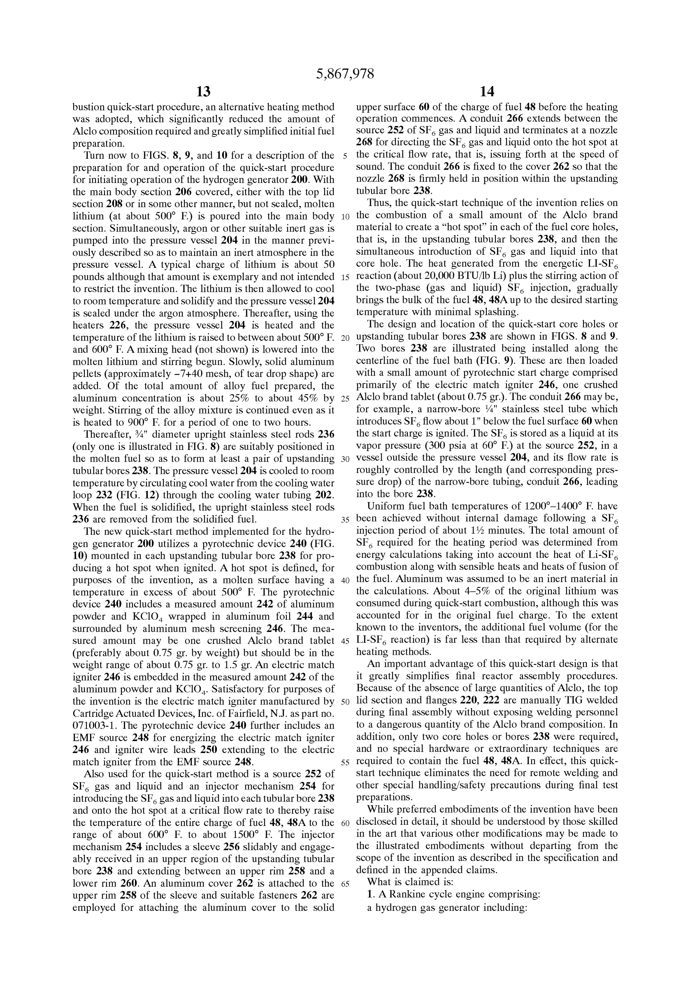
lower rim 260. An aluminum cover 262 is attached to the 65 What is claimed is:
upper rim 258 of the sleeve and suitable fasteners 262 are 1. A Rankine cycle engine comprising: employed for attaching the aluminum cover to the Solid a hydrogen gas generator including:
Page 20
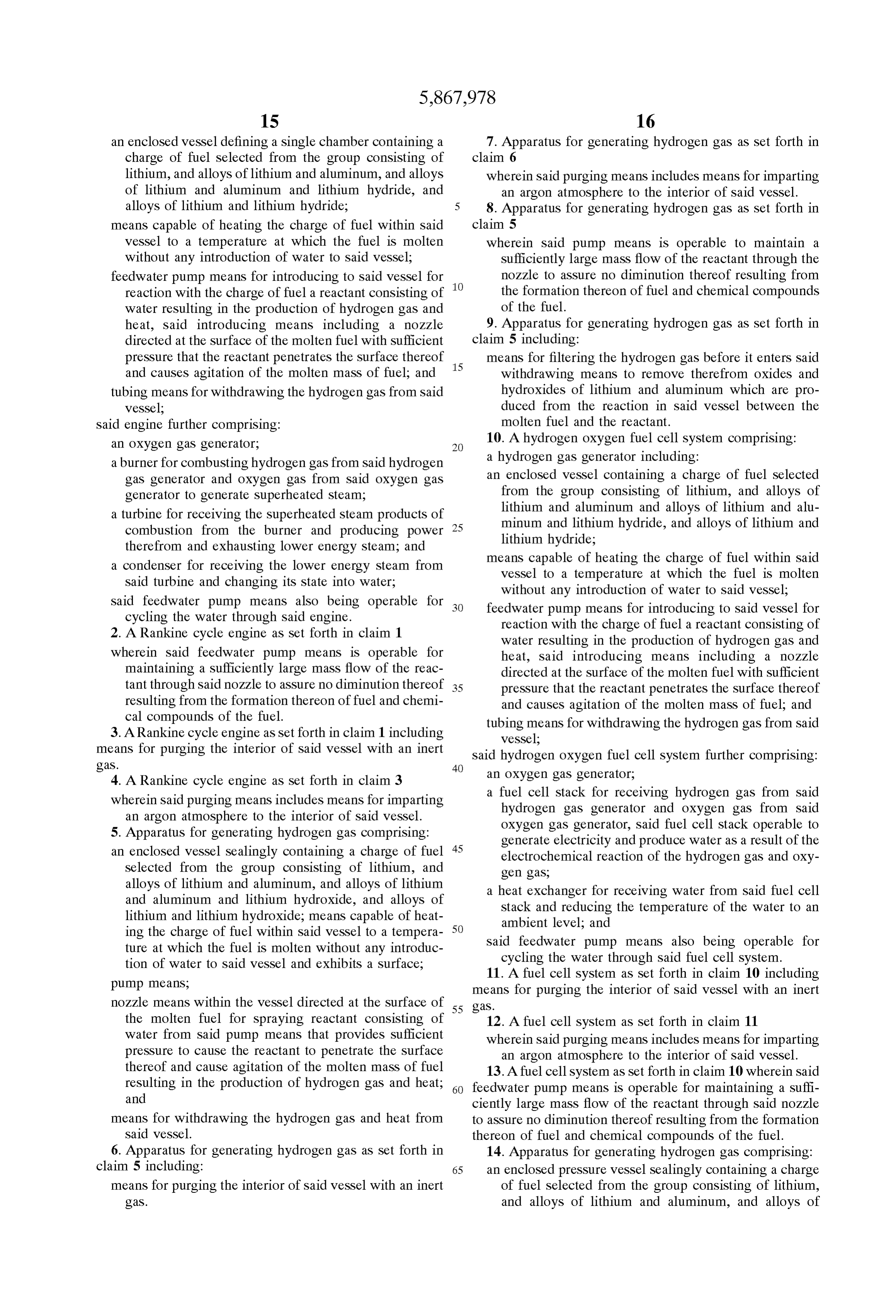
an enclosed vessel defining a Single chamber containing a 7. Apparatus for generating hydrogen gas as Set forth in charge of fuel Selected from the group consisting of claim 6 lithium, and alloys of lithium and aluminum, and alloys wherein Said purging means includes means for imparting of lithium and aluminum and lithium hydride, and an argon atmosphere to the interior of Said vessel. alloys of lithium and lithium hydride; 5 8. Apparatus for generating hydrogen gas as Set forth in means capable of heating the charge of fuel within Said claim 5 vessel to a temperature at which the fuel is molten wherein Said pump means is operable to maintain a without any introduction of water to Said vessel; Sufficiently large mass flow of the reactant through the feedwater pump means for introducing to Said vessel for nozzle to assure no diminution thereof resulting from reaction with the charge of fuel a reactant consisting of the formation thereon of fuel and chemical compounds water resulting in the production of hydrogen gas and of the fuel.
heat, Said introducing means including a nozzle 9. Apparatus for generating hydrogen gas as Set forth in directed at the Surface of the molten fuel with Sufficient claim 5 including:
preSSure that the reactant penetrates the Surface thereof 15 means for filtering the hydrogen gas before it enterS Said and causes agitation of the molten mass of fuel; and withdrawing means to remove therefrom oxides and tubing means for withdrawing the hydrogen gas from Said hydroxides of lithium and aluminum which are pro vessel; duced from the reaction in Said vessel between the Said engine further comprising: molten fuel and the reactant. an OXygen gas generator, 10. A hydrogen oxygen fuel cell System comprising: a burner for combusting hydrogen gas from Said hydrogen a hydrogen gas generator including: gas generator and oxygen gas from Said oxygen gas an enclosed vessel containing a charge of fuel Selected generator to generate Superheated Steam; from the group consisting of lithium, and alloys of a turbine for receiving the Superheated Steam products of lithium and aluminum and alloys of lithium and alu combustion from the burner and producing power 25 minum and lithium hydride, and alloys of lithium and therefrom and exhausting lower energy Steam; and lithium hydride;
a condenser for receiving the lower energy Steam from means capable of heating the charge of fuel within Said Said turbine and changing its State into water; vessel to a temperature at which the fuel is molten without any introduction of water to Said vessel;
Said feedwater pump means also being operable for feedwater pump means for introducing to Said vessel for cycling the water through said engine. reaction with the charge of fuel a reactant consisting of 2. A Rankine cycle engine as Set forth in claim 1 water resulting in the production of hydrogen gas and wherein said feedwater pump means is operable for heat, Said introducing means including a nozzle maintaining a Sufficiently large mass flow of the reac directed at the Surface of the molten fuel with Sufficient tant through Said nozzle to assure no diminution thereof 35 preSSure that the reactant penetrates the Surface thereof resulting from the formation thereon of fuel and chemi and causes agitation of the molten mass of fuel; and cal compounds of the fuel. tubing means for withdrawing the hydrogen gas from Said 3. A Rankine cycle engine as Set forth in claim 1 including vessel;
means for purging the interior of Said vessel with an inert Said hydrogen oxygen fuel cell System further comprising: gaS. 40 4. A Rankine cycle engine as Set forth in claim 3 an OXygen gas generator, wherein Said purging means includes means for imparting a fuel cell Stack for receiving hydrogen gas from Said an argon atmosphere to the interior of Said vessel. hydrogen gas generator and oxygen gas from Said 5. Apparatus for generating hydrogen gas comprising: Oxygen gas generator, Said fuel cell Stack operable to generate electricity and produce water as a result of the an enclosed vessel Sealingly containing a charge of fuel 45 electrochemical reaction of the hydrogen gas and oxy Selected from the group consisting of lithium, and gen gaS, alloys of lithium and aluminum, and alloys of lithium a heat eXchanger for receiving water from Said fuel cell and aluminum and lithium hydroxide, and alloys of Stack and reducing the temperature of the water to an lithium and lithium hydroxide; means capable of heat ambient level; and ing the charge of fuel within Said vessel to a tempera 50 Said feedwater pump means also being operable for ture at which the fuel is molten without any introduc cycling the water through said fuel cell System. tion of water to Said vessel and exhibits a Surface, pump means, 11. A fuel cell system as set forth in claim 10 including means for purging the interior of Said vessel with an inert nozzle means within the vessel directed at the Surface of 55 gaS.
the molten fuel for Spraying reactant consisting of 12. A fuel cell system as set forth in claim 11 water from Said pump means that provides Sufficient wherein Said purging means includes means for imparting preSSure to cause the reactant to penetrate the Surface an argon atmosphere to the interior of Said vessel. thereof and cause agitation of the molten mass of fuel 13. A fuel cell system as set forth in claim 10 wherein said resulting in the production of hydrogen gas and heat; 60 feedwater pump means is operable for maintaining a Suffi and ciently large mass flow of the reactant through Said nozzle means for withdrawing the hydrogen gas and heat from to assure no diminution thereof resulting from the formation Said vessel. thereon of fuel and chemical compounds of the fuel. 6. Apparatus for generating hydrogen gas as Set forth in 14. Apparatus for generating hydrogen gas comprising: claim 5 including: 65 an enclosed pressure vessel Sealingly containing a charge means for purging the interior of Said vessel with an inert of fuel Selected from the group consisting of lithium, gaS. and alloys of lithium and aluminum, and alloys of
Page 21
lithium and aluminium and lithium hydride, and alloys wherein Said injector means includes: of lithium and lithium hydride; a sleeve Slidably and engageably received in an upper means capable of heating the charge of fuel within Said region of the upstanding tubular bore and extending preSSure vessel to a temperature at which the fuel is between an upper rim and a lower rim; molten without any introduction of water to Said vessel an aluminum cover attached to Said upper rim of Said and exhibits a Surface; sleeve;
first tubing for injecting reactant water in Said pressure fastening means for attaching Said aluminum cover to the vessel; Solid upper Surface of the charge of fuel before the an intake external of Said pressure vessel for directing 1O heating operation commences, and flow of water into said first tubing; a conduit extending between Said Source of SF gas and pump means, liquid and terminating at a nozzle for directing the SF nozzle means on Said first tubing within Said pressure gas and liquid onto the hot spot at the critical flow rate. vessel directed at the Surface of the molten fuel for 20. A process for generating hydrogen gas comprising the Spraying a reactant consisting of water from Said pump 15 Steps of means that provides Sufficient pressure to cause the (a) containing a charge of Solid fuel Selected from the reactant to penetrate the Surface thereof and cause group consisting of lithium, and alloys of lithium and agitation of the molten mass of fuel resulting in the aluminum, and alloys of lithium and aluminum and production of hydrogen gas and heat; and lithium hydride, and alloys of lithium and lithium means for withdrawing the hydrogen gas from Said pres hydride in an enclosed pressure vessel defining a Single Sure vessel; chamber;
Second tubing for directing flow of cooling water to and (b) Sealing the pressure vessel; away from Said pressure vessel; (c) heating the charge of Solid fuel within the pressure an intake external of Said pressure vessel for directing 25 vessel to a temperature at which the fuel is a molten flow of cooling water into Said Second tubing, and mass and exhibits a Surface; an outlet external of Said pressure vessel for withdrawing (d) introducing to the pressure vessel for reaction with the molten mass of fuel within the pressure vessel a reac
Steam from Said Second tubing. tant consisting of water resulting in the production of 15. Apparatus for generating hydrogen gas as Set forth in hydrogen gas and heat, Said Step of introducing a claim 14 wherein Said pressure vessel includes an outer wall; reactant including the Steps of and (i) spraying the reactant through a nozzle directed at the wherein Said Second tubing is integral with Said outer Surface of the molten fuel Such that the reactant Wall. penetrates the Surface thereof and causes agitation of 16. Apparatus for generating hydrogen gas as Set forth in the molten mass of fuel; claim 14 wherein Said Second tubing includes a coil within 35 (ii) performing a first phase reaction which produces Said pressure vessel. LiH and a first quantity of heat; and 17. Apparatus for generating hydrogen gas as Set forth in (iii) performing a Second phase reaction which pro claim 14 duces H and a second quantity of heat, Substantially wherein Said heating means includes a plurality of electric less than the first quantity of heat, and band and Strip heaters clamped on the outside of Said 40 (e) withdrawing the hydrogen gas and heat from the preSSure vessel. preSSure vessel.
18. Apparatus as set forth in claim 14 wherein, prior to the 21. A process for generating hydrogen gas as Set forth in heating operation, the charge of fuel is Solid and has at least claim 20 wherein step (d)(i) is performed according to a one upstanding tubular bore formed therein; and including: Stoichiometric reaction equation, as follows: a pyrotechnic device mounted in each upstanding tubular 45 bore for producing a hot Spot when ignited whereat the upstanding bore exhibits a molten Surface having a wherein step (d)(iii) is performed according to a stoichio temperature in excess of about 500 F.; metric reaction equation defining operations performed at a Source of SF gas and liquid; and 50 elevated pressures in excess of about 100 psia, as follows:
injector means for introducing said SF gas and liquid into (x) Li+A1+(y)LiH+(x+y+3)/2.H.O->LiAlO+(x+y-1)/2. LiO+(x+
each tubular bore and onto the hotspot at a critical flow rate thereby raising the temperature of the entire charge where X=the stoichiometric coefficient for Li (lithium) nor of fuel to the range of about 600 F. to about 1500 F. malized by the coefficient for Al (aluminum); 19. Apparatus as set forth in claim 18 55 where y=the stoichiometric coefficient for LiH (lithium wherein the charge of fuel exhibits a Solid upper Surface hydride) normalized by the coefficient for Al (aluminum); when the charge of fuel is solidified; and wherein Said pyrotechnic device includes: where y (LiH) and X (Li) are in the molar ratio range of about
a measured amount of aluminum powder and KClO. 60 22. A process for generating hydrogen gas as Set forth in wrapped in aluminum foil and Surrounded by alumi claim 20 wherein step (d) (iii) is initiated when the molar num mesh Screening; ratio of LiH and Li reaches a point in the range between an electric match embedded in Said measured amount of about 1:1 and about 2:1.
aluminum powder and KClO; 23. A process for generating hydrogen gas comprising the an EMF Source for energizing Said electric match; and 65 Steps of igniter wire leads extending to Said electric match from (a) introducing into a pressure vessel defining a single said EMF source; and. chamber a molten charge of fuel Selected from the
Page 22
group consisting of lithium, and alloys of lithium and (i) withdrawing the hydrogen gas and heat from the aluminum, and alloys of lithium and aluminum and preSSure vessel.
lithium hydride, and alloys of lithium and lithium 24. A process for generating hydrogen gas as Set forth in hydride; claim 23 (b) allowing the charge of fuel to solidify; 5 (j) wherein the pyrotechnic device includes a measured (c) forming at least one upstanding tubular bore in the amount of KCIO and aluminum powder located in the Solidified charge of fuel extending downwardly from an upstanding bore in an amount in the range of about 0.75 upper Surface thereof; gr. to about 1.5 gr.
25. A process for generating hydrogen gas comprising the (d) inserting a pyrotechnic device into each upstanding Steps of tubular bore; (a) introducing into a pressure vessel defining a single (e) Sealing the pressure vessel against further introduction chamber a molten charge of fuel Selected from the of the fuel into the pressure vessel; group consisting of lithium, and alloys of lithium and (f) igniting the pyrotechnic device to produce a hot spot aluminum, and alloys of lithium and aluminum and in the upstanding bore whereat the upstanding bore 15 lithium hydride, and alloys of lithium and lithium exhibits a molten Surface having a temperature in hydride;
excess of about 500 F.; (e) Sealing the pressure vessel; (g) introducing a flow of SF gas and liquid into each (f) externally heating the charge of solid fuel within the upstanding tubular bore and onto the hot Spot produced preSSure vessel to a temperature at which the fuel is a in step (f) at a critical flow rate thereby raising the molten mass and exhibits a Surface; temperature of the entire charge of fuel to the range of (g) introducing to the pressure vessel for reaction with the about 600 F to about 1500 F. Such that the entire molten mass of fuel within the pressure vessel a reac charge of fuel is a molten mass and exhibits a Surface; tant consisting of water resulting in the production of and hydrogen gas and heat, Said Step of introducing a (h) introducing to the pressure vessel for reaction with the 25 reactant including the Step of Spraying the reactant molten mass of fuel within the preSSure vessel a reac through a nozzle directed at the Surface of the molten tant consisting of water resulting in the production of fuel Such that the reactant penetrates the Surface thereof hydrogen gas and heat, Said Step of introducing a and causes agitation of the molten mass of fuel; and reactant including the Step of Spraying the reactant (h) withdrawing the hydrogen gas and heat from the through a nozzle directed at the Surface of the molten preSSure vessel.
fuel Such that the reactant penetrates the Surface thereof and causes agitation of the molten mass of fuel; and
Provenance
- Collection
- Cited prior art
- Original PDF
- patentimages.storage.googleapis.com →
- Filed
- 1997-05-09
- Pages
- 22
- Method
- pdftotext (the PDF's own text layer) + pdftoppm 300dpi page scans
- Source
- Google Patents bibliographic record
- Granted
- 1999-02-09
- Inventors
- Martin Klanchar; Thomas G. Hughes; Penn State Research Foundation
- Transcribed from
- patentimages.storage.googleapis.com →