patent · US4055962
Hydrogen-hydride absorption systems and methods for refrigeration and heat pump cycles
1 November 1977
Page 1 — bibliographic record
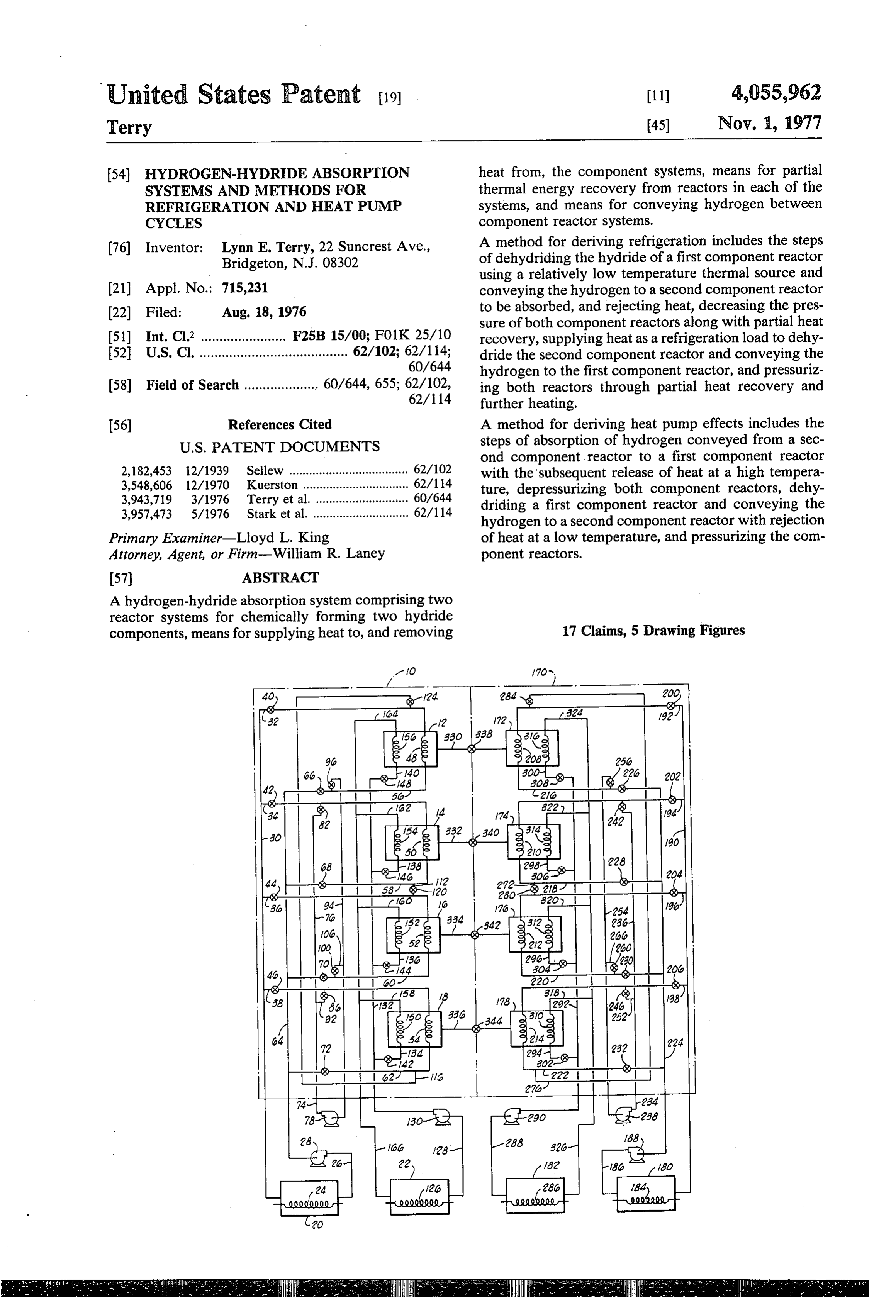
United States Patent (19) 11) 4,055,962 Terry 45) Nov. 1, 1977 54) HYDROGEN-HYDRDE ABSORPTION heat from, the component systems, means for partial SYSTEMS AND METHODS FOR thermal energy recovery from reactors in each of the REFRIGERATION AND HEAT PUMP systems, and means for conveying hydrogen between CYCLES component reactor systems.
76) Inventor: Lynn E. Terry, 22 Suncrest Ave., A method for deriving refrigeration includes the steps Bridgeton, N.J. 08302 of dehydriding the hydride of a first component reactor using a relatively low temperature thermal source and (21) Appl. No.: 715,231 conveying the hydrogen to a second component reactor 22 Filed: Aug. 18, 1976 to be absorbed, and rejecting heat, decreasing the pres sure of both component reactors along with partial heat 51) Int. Cl.2 ....................... F2B15/9992/9 recovery, supplying heat as a refrigeration load to dehy 52 U.S. Cl. ........................................ 62/102; 62/114; dride the second component reactor and conveying the O 60/644 hydrogen to the first component reactor, and pressuriz 58 Field of Search .................... 60/644, 655; 62/102, ing both reactors through partial heat recovery and
(56) References Cited A method for deriving heat pump effects includes the
ond component, reactor to a first component reactor 3. 5,E8 Six s as ss a s s e a o 8 as a : with the 'subsequent release of heat at a high tempera 3543715 3/1976 I i". , ture, depressurizing both component reactors, dehy 3,957,473 5/1976 starket al. driding a tofirsta second hydrogen component reactorreactor component and conveying the with rejection
Primary Examiner-Lloyd L. King of heat at a low temperature, and pressurizing the com Attorney, Agent, or Firm-William R. Laney ponent reactors.
A hydrogen-hydride absorption system comprising two reactor systems for chemically forming two hydride components, means for supplying heat to, and removing 17 Claims, 5 Drawing Figures
40 &-124 284 Ns zo,
Page 2
Drawing sheet — no readable text.
Page 3
Drawing sheet — no readable text.
Page 4
ous product discharged from the reactor bank in the
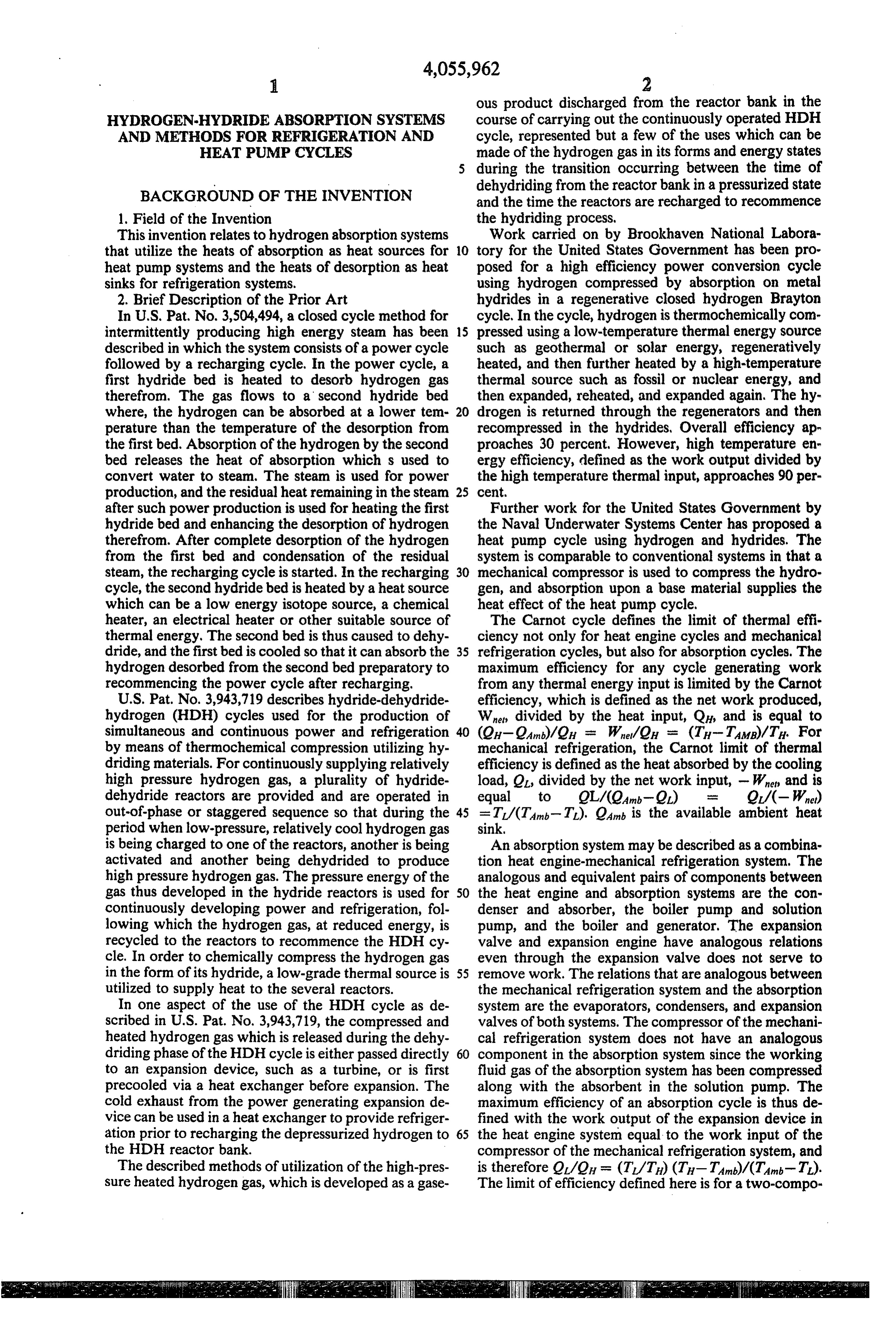
HYDROGEN.HYDRIDE ABSORPTION SYSTEMS course of carrying out the continuously operated HDH AND METHODS FOR REFRIGERATION AND cycle, represented but a few of the uses which can be HEAT PUMP CYCLES made of the hydrogen gas in its forms and energy states during the transition occurring between the time of dehydriding from the reactor bank in a pressurized state
BACKGROUND OF THE INVENTION and the time the reactors are recharged to recommence the hydriding process, 1. Field of the Invention
This invention relates to hydrogen absorption systems Work carried on by Brookhaven National Labora that utilize the heats of absorption as heat sources for O tory for the United States Government has been pro heat pump systems and the heats of desorption as heat posed for a high efficiency power conversion cycle sinks for refrigeration systems. using hydrogen compressed by absorption on metal 2. Brief Description of the Prior Art hydrides in a regenerative closed hydrogen Brayton In U.S. Pat. No. 3,504,494, a closed cycle method for cycle. In the cycle, hydrogen is thermochemically comr intermittently producing high energy steam has been 5 pressed using a low-temperature thermal energy source described in which the system consists of a power cycle such as geothermal or solar energy, regeneratively followed by a recharging cycle. In the power cycle, a heated, and then further heated by a high-temperature first hydride bed is heated to desorb hydrogen gas thermal source such as fossil or nuclear energy, and therefrom. The gas flows to a second hydride bed then expanded, reheated, and expanded again. The hy where, the hydrogen can be absorbed at a lower tem 20 drogen is returned through the regenerators and then perature than the temperature of the desorption from recompressed in the hydrides, Overall efficiency ap the first bed. Absorption of the hydrogen by the second proaches 30 percent. However, high temperature enr bed releases the heat of absorption which s used to ergy efficiency, defined as the work output divided by convert water to steam. The steam is used for power the high temperature thermal input, approaches 90 per production, and the residual heat remaining in the steam 25 Cent.
after such power production is used for heating the first Further work for the United States Government by hydride bed and enhancing the desorption of hydrogen the Naval Underwater Systems Center has proposed a therefrom. After complete desorption of the hydrogen heat pump cycle using hydrogen and hydrides. The from the first bed and condensation of the residual system is comparable to conventional systems in that a steam, the recharging cycle is started. In the recharging 30 mechanical compressor is used to compress the hydro cycle, the second hydride bed is heated by a heat source gen, and absorption upon a base material supplies the which can be a low energy isotope source, a chemical heat effect of the heat pump cycle, heater, an electrical heater or other suitable source of The Carnot cycle defines the limit of thermal effi thermal energy, The second bed is thus caused to dehy ciency not only for heat engine cycles and mechanical dride, and the first bed is cooled so that it can absorb the 35 refrigeration cycles, but also for absorption cycles. The hydrogen desorbed from the second bed preparatory to maximum efficiency for any cycle generating work recommencing the power cycle after recharging. from any thermal energy input is limited by the Carnot U.S. Pat. No. 3,943,719 describes hydride-dehydride efficiency, which is defined as the network produced, hydrogen (HDH) cycles used for the production of We divided by the heat input, Q, and is equal to simultaneous and continuous power and refrigeration 40 (OH-OAn)/2 = Wet/OH = (TH-TAMB)/Th. For by means of thermochemical compression utilizing hy mechanical refrigeration, the Carnot limit of thermal driding materials. For continuously supplying relatively efficiency is defined as the heat absorbed by the cooling high pressure hydrogen gas, a plurality of hydride load, O, divided by the net work input, - W and is dehydride reactors are provided and are operated in equal to QL/(OAn-2) O/(-W) out-of-phase or staggered sequence so that during the 45 =T/(TA-T). Oan is the available ambient heat period when low-pressure, relatively cool hydrogen gas sink.
is being charged to one of the reactors, another is being An absorption system may be described as a combina activated and another being dehydrided to produce tion heat engine-mechanical refrigeration system. The high pressure hydrogen gas. The pressure energy of the analogous and equivalent pairs of components between gas thus developed in the hydride reactors is used for 50 the heat engine and absorption systems are the con continuously developing power and refrigeration, fol denser and absorber, the boiler pump and solution lowing which the hydrogen gas, at reduced energy, is pump, and the boiler and generator. The expansion recycled to the reactors to recommence the HDH cy valve and expansion engine have analogous relations cle. In order to chemically compress the hydrogen gas even through the expansion valve does not serve to in the form of its hydride, a low-grade thermal source is 55 remove work. The relations that are analogous between utilized to supply heat to the several reactors. the mechanical refrigeration system and the absorption In one aspect of the use of the HDH cycle as de system are the evaporators, condensers, and expansion scribed in U.S. Pat. No. 3,943,719, the compressed and valves of both systems. The compressor of the mechani heated hydrogen gas which is released during the dehy cal refrigeration system does not have an analogous driding phase of the HDH cycle is either passed directly 60 component in the absorption system since the working to an expansion device, such as a turbine, or is first fluid gas of the absorption system has been compressed precooled via a heat exchanger before expansion. The along with the absorbent in the solution pump. The cold exhaust from the power generating expansion de maximum efficiency of an absorption cycle is thus de vice can be used in a heat exchanger to provide refriger fined with the work output of the expansion device in ation prior to recharging the depressurized hydrogen to 65 the heat engine system equal to the work input of the the HDH reactor bank. compressor of the mechanical refrigeration system, and The described methods of utilization of the high-pres is therefore QL/OH = (T/T) (Ty-Tant)/(Tam-T). sure heated hydrogen gas, which is developed as a gase The limit of efficiency defined here is for a two-compo
Page 5
nent system. If the system had operated with a three BRIEF DESCRIPTION OF THE PRESENT component system, then the ratio of QL/Q is on a dif INVENTION ferent per-unit mass basis and the Carnot limit would not be the same as a two-component system. A three New absorption refrigeration and heat pump systems component system might consist of ammonia and two 5 and methods for effectively conserving our energy re organic or inorganic solvents. In a hydrogen absorption sources are presented by this invention. Refrigeration System, the hydrogen would be the primary working and heating are continuously and efficiently generated fluid, and any of several different classes of reversible directly from the heats of desorption and absorption, hydriding materials could be utilized as the two or more respectively, of three or more component hydrogen absorbents. Therefore, the ratio Q/Q of an absorption 10 absorption systems. Hydrogen-hydride absorption sys System utilizing three or more components depends on tems have the advantage over other conventional ab the Carnot limit of thermal efficiency in a different way sorption systems in that the hydrogen remains a gas at in that the limit is mass-dependent. one atmosphere pressure down to 20 K and can oper A heat pump system is essentially a mechanical refrig ate over a range of temperatures up to the melting point eration system with a different objective in view. The 15 of many metals. Hydrogen absorption systems require rejected energy in the refrigeration cycle becomes use no mechanical energy input, and operation is totally ful energy. The heat input is to be the evaporator from thermochemical, with the driving potential caused by some ambient heat source. The efficiency is defined as relative pressure differences. The thermally induced the useful heat rejected, Qt, divided by the net work driving potential therefore requires at least two differ input, -Wel, which is equal to Q/- W. 20 ent temperature levels.
QH/OH-9Ami) = Thi?(TH-Tamb). If an absorption sys Broadly described, the refrigeration and heat pump tem is again considered as a combination heat pump and systems of this invention comprise a plurality of hydride heat engine system, with the heat engine operating with reactors consisting of at least two component hydrida a heat source at ambient conditions and a heat sink at ble materials, means for conveying hydrogen gas be some lower temperature T, the efficiency of the heat 25 tween component reactor systems, means for supplying engine would be QAnt/Wnet = QAnt/(QAnt-QL) = heat to each component reactor system in out-of-phase, Tamb/(Tan-T). The combined absorption system staggered cycles to each reactor of the component sys efficiency can be defined again with the the work out tems, and means for removing heat from the reactors of put of the heat engine system equal to the work input to the component systems. . the heat pump system as Qu/Qant'= (Th/Tamb) 30 The invention includes a sequential method that ide (Tam-T)/(Tu-Tan) where the Qant is only the heat ally includes the steps of reversibly combining hydro input to the heat engine system. This defined efficiency gen with a hydride-forming material for one of the two of the absorption system is also massdependent for a or more component hydride systems, heating the hy system of three or more components. dride at constant volume to effectively chemically com A factor that is coming into more use recently is the 35 press the hydrogen gas, reversibly dehydriding the concept of the energy utilization factor. This factor is hydride-forming materials, and cooling the substantially defined as the desired energy transfer divided by the dehydrided material under constant volume to effect fuel input from the basic energy resource. Thus, typi chemical decompression so as to effectively recondition cally, a natural gas furnace would have an E.U.F. of the hydride-forming material, and then cyclically re approximately 0.69, as 31 percent of the heat content of 40 peating these steps. At the same time as the above steps the natural gas is lost up the stack. For a heat pump, the are proceeding, at least one of the two or more compo E.U.F. is typically about 0.77, with the basic energy nent hydride systems is operating with the above steps resource being the fossil fuel or nuclear fuel to an elec in reverse order. The preferred practice of the method tric generating plant. The E.U.F. could be much higher of the invention entails carrying out the described steps for the heat pump if more of the energy, such as the 45 in staggered or out-of-phase relationship for each of the rejected heat of the electric generating plant, were used. component hydride-forming materials, using a plurality For example, if an electric generating plant received 1 of discrete reactor beds to develop a substantially con Joule of thermal energy as a heat input and rejected 0.7 tinuous refrigeration sink or heat source. Joule, 0.3Joule of energy would be produced as electri In certain embodiments of the invention, the refriger cal energy. This 0.3Joule of electricity used with a heat 50 ation system may act as a heat sink so that systems in pump of 2.0 efficiency would produce 0.6Joule of use series may be operated to supply a refrigeration sink of ful heat at the point of use. If the rejected heat of the substantially lower temperature. electric generating plant could also be used, the E.U.F. In another embodiment of the invention, the heat would become 1.30. An absorption system using the pump system may act as a heat source so that systems in combined systems of a heat engine and mechanical 55 series may be operated to supply a heat source of sub refrigeration analogy, and operating with a heat source stantially higher temperature.
of 1 Joule as a high-temperature input to the generator, An important object of the invention is to provide a could reject 2 Joules as a useful energy transfer such as novel means for producing a more efficient refrigera heating a home, with one of the Joules coming from the tion and heat pump means than the conventional two heat engine condenser and the other Joule coming from component systems.
the refrigerator condenser. The available refrigeration Another important object of the invention is to pro would also be 1 Joule, and the E.U.F. for such a system vide a totally thermochemical means of producing re would be 3.0. This high efficiency is only possible if the frigeration sinks and heat sources. efficiency is mass-dependent, as with a three-compo Another object is to provide a simple and efficient nent system. Thus, effective utilization of the rejected 65 means of separation of the absorber and the absorbent. heat of an absorption system of three or more compo Additional objects and advantages of the invention nents can mean a relatively high energy utilization fac will become apparent as the following detailed descrip tor. tion of certain embodiments of the invention, and de
Page 6
tailed examples thereof, are read in conjunction with and 60 via valves 96 and 100, respectively. It will also be the accompanying drawings which illustrate certain noted that valve 100 is located in the short conduit 106 preferred applications of the invention. which connects the manifold 94 to branch return con
BRIEF DESCRIPTION OF THE DRAWINGS
duit 60. Sensible heat recovery conduits 112 and 16 are provided in the heat recovery loop 74, with conduit 112
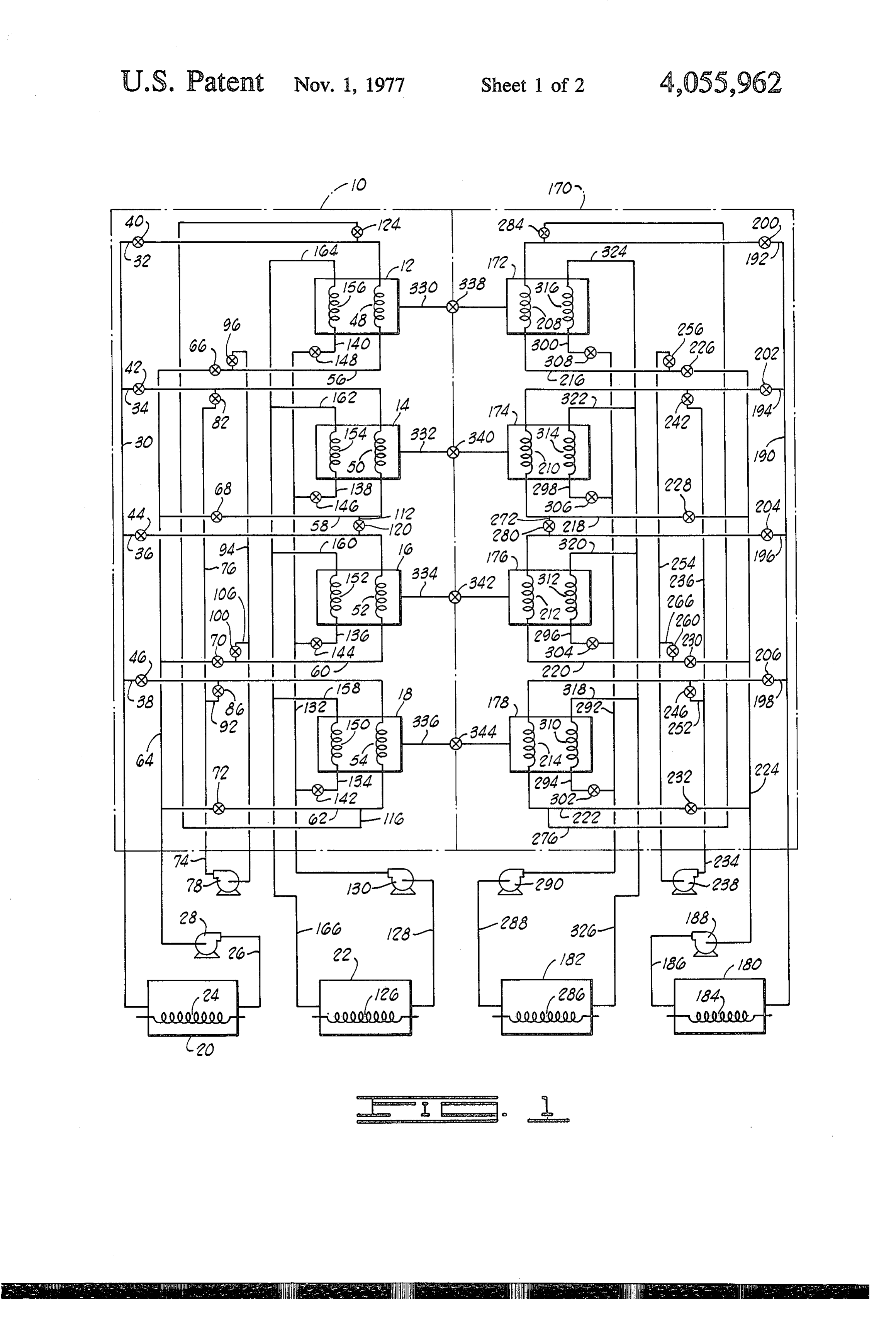
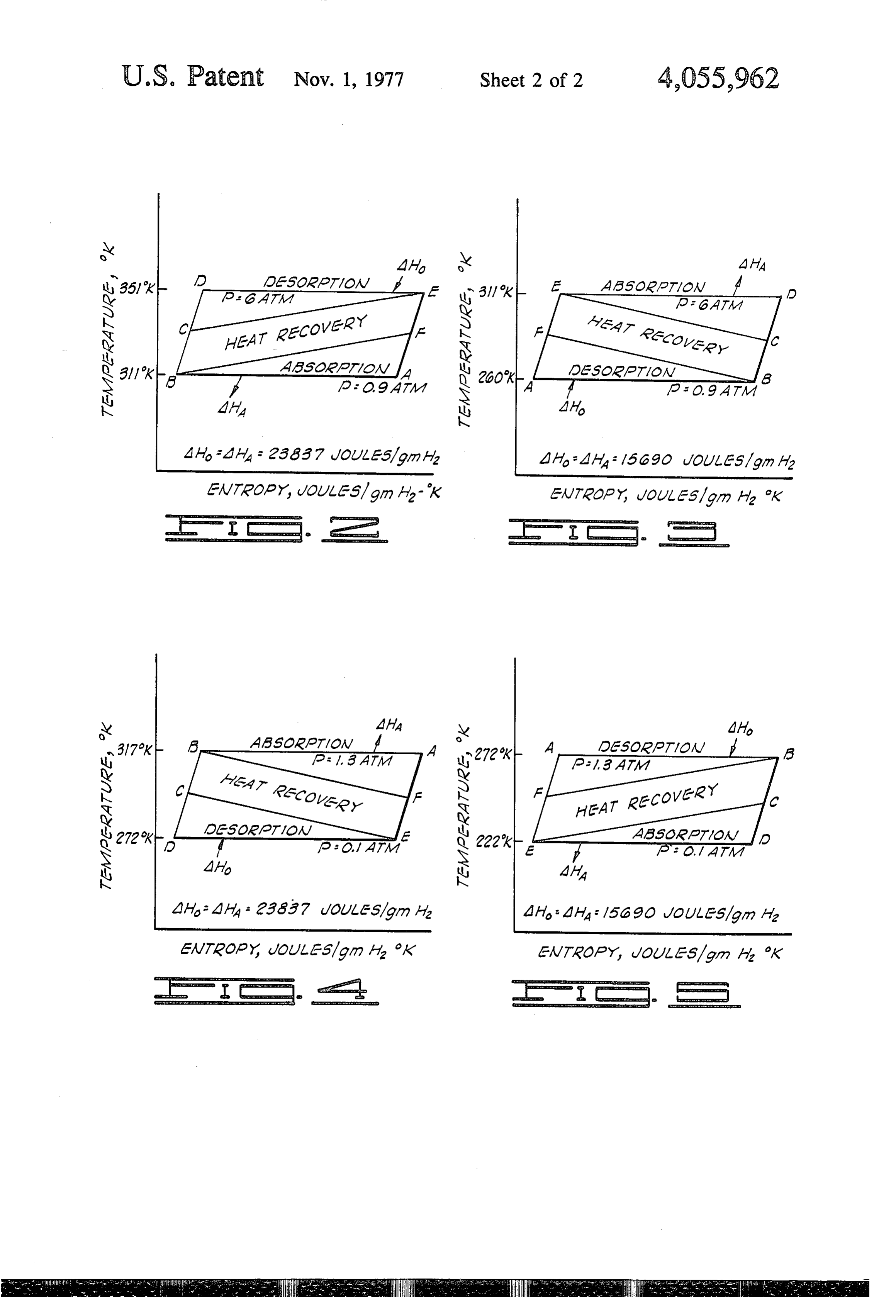
FIG. 1 is a schematic flow diagram illustrating the extending between the branch conduit 58 and the hydrogen-hydride absorption component systems and branch conduit 36 and containing valve 120. Conduit heat exchangers. 116 interconnects the branch conduit 62 and branch FIG. 2 is a temperature-entropy diagram for the base conduit 32 and contains valve 124. material LaNi4Cu used in one of the component systems O An ambient temperature heat exchange fluid is sup illustrated in FIG. 1 and operating in the refrigeration plied through heat exchange coil 126 and removes heat mode as the heat engine cycle. from the heat exchange fluid contained in loop 128. The FIG. 3 is a temperature-entropy diagram for the base heat exchange fluid from heat exchanger 22 is charged material FeTi used in the second component System through feed pump 130 to system. 10 through manifold illustrated in FIG. 1 of the refrigeration mode of opera 15 132 and is admitted, in a sequence hereinafter described, tion and used as the refrigeration cycle. to the reactors 12-18 through branch conduits 134, 136, FIG. 4 is a temperature-entropy diagram for the base 138, and 140, respectively, containing valves 142, 144, material LaNi4Cu of one of the component systems 146, and 148. The branch conduits 134-140 are respec operating in a heat pump mode and used as the heat tively connected to heat exchange coils 150, 152, 154, pump cycle. 20 and 156 located in reactors 12-18 and respectively con FIG. 5 is a temperature-entropy diagram for the base nected by branch return conduits 158, 160, 162, and 164 material FeTi of the second component system operat to return manifold 66.
ing in a heat pump mode as the heat engine cycle. Hydride component reactor system 170 consists of a system equivalent to hydride component reactor system
DETAILED DESCRIPTION OF PREFERRED 25 10. System 170 is the refrigeration equivalent of a me EMBODIMENTS OF THE INVENTION chanical refrigeration system, and as such, heat ex Referring initially to FIG. 1 of the drawings, two changer 180 serves as the refrigeration means to heat identical hydride reactor systems 10 and 170, each con exchange coil 184, and serves to supply heat to the heat taining a different hydriding material, are illustrated, exchange fluid contained in loop 186. The heat ex with hydride reactors 12, 14, 16, and 18 in system 10, change fluid is charged to heat exchanger 180 through and hydride reactors 172, 174,176, and 178 in system feed pump 188. The heat exchange fluid from heat ex 170. There are two different modes of operation, with changer 180 is charged to system 170 through manifold one mode supplying refrigeration as its primary func 190 and is admitted, in a sequence hereinafter described, tion, and the other mode supplying a heat source to the reactors 172-178 through branch conduits 192, through a heat pump action. Each mode of operation is 35 194, 196, and 198 via valves 200, 202, 204, and 206, controlled through heat exchangers 20 and 22 of system respectively. The branch conduits 192-198 are respec 10, and heat exchangers 180 and 182 of system 170. Heat tively connected to heat exchange loops 208, 210, 212, exchangers 20 and 22 of component system 10 and heat and 214 located in reactors 172-178. The heat exchange exchangers 180 and 182 of component system 170 may coils 208-214 are also connected through branch return serve to supply heat to, or remove heat from each of 40 conduits 216, 218, 220, and 222, respectively, to a return their respective component systems, depending on the manifold conduit 224 through valves 226, 228, 230, and mode of operation. 232.
For purposes of illustration, the mode of operation A heat recovery loop 234 supplies a heat exchange will be the refrigeration mode, with component system fluid to a manifold 236 from heat recovery pump 238 to 10 acting as the heat engine system and system 170 45 the reactors 174 and 178 through branch conduits 194 acting as the refrigeration system. A relatively high and 198 via valves 242 and 246. It will be noted that temperature heat exchange fluid is supplied through valve 246 is located in the short conduit section 252 heat exchange coil 24 and supplies heat to the heat which connects the manifold 236 to the branch conduit exchange fluid contained in loop 26. The heat exchange 198. A return manifold 254 is connected to branch re fluid is charged to heat exchanger 20 through feed 50 turn conduits 216 and 220 via valves 256 and 260, re pump 28. The heat exchange fluid from heat exchanger spectively. Valve 260 is located in the short conduit 20 is charged to system 10 through manifold 30 and is 266. Sensible heat recovery conduits 272 and 276 are admitted, in a sequence hereinafter described, to the provided in the recovery loop 234, with conduit 272 reactors 12-18 through branch conduits 32, 34, 36, and extending between the branch conduit 218 and the 38 via valves 40, 42, 44, and 46, respectively. The 55 branch conduit 196 and containing valve 280. Conduit branch conduits 32-38 are respectively connected to 276 interconnects the branch conduit 222 and branch heat exchange coils 48, 50, 52, and 54 located in the conduit 192 and contains valve 284. reactors 12-18. The heat exchange coils 48-54 are also An ambient temperature heat exchange fluid is sup connected through branch return conduits 56, 58, 60, plied through heat exchange coil 286 and removes heat and 62, respectively, to a return manifold conduit 64 60 from the heat exchange fluid contained in loop 288. The through valves 66, 68, 70, and 72. heat exchange fluid from heat exchanger 182 is charged A heat recovery loop 74 supplies a heat exchange from feed pump 290 to system 170 through manifold fluid to manifold 76 from heat recovery pump 78 to the 292 and is admitted, in a sequence herein-after de reactors 14 and 18 through branch conduits 34 and 38 scribed, to the reactors 172-178 through the branch via valves 82 and 86. It will be noted that valve 86 is 65 conduits 294, 296, 298, and 300, respectively, through located in the short conduit section 92 which connects valves 302, 304, 306, and 308. The branch conduits the manifold 76 to the branch conduit 38. A return 294-300 are respectively connected to heat exchange manifold 94 is connected to branch return conduits 56 loops 310, 312, 314, and 316 located in the reactors
Page 7
172-178. The heat exchange coils 310-316 are also con 172 be in a dehydriding phase to supply hydrogen via nected through branch return conduits 318, 320, 322, conduit 330 to reactor 12, that reactor 174 be activating and 324, respectively, to a return manifold conduit 326. preparatory to hydriding reactor 14 in the second se In the refrigeration mode of operation, a relatively quential step of a complete cycle, that reactor 176 be hot heat exchange fluid is supplied to heat exchanger 20 5 deactivating, and that reactor 178 be hydriding by through coil 24 to heat the fluid in loop 26, which means of hydrogen supplied via conduit 336 from reac supplies the heat of desorption sequentially to one of the tor 18, which is dehydriding. Table I more lucidly de reactors 12-18 through coils 48-54, respectively, of scribes each step in a cycle for each reactor. system 10. The heat recovery loop 74 serves to recover TABLE I a substantial part of the sensible heat contained in the 10 Re reactors 12-18 after complete desorption. The heat of actor Phase I Phase II Phase II Phase IV absorption produced upon hydriding one of the reactors 12 Hydriding Activating Dehydriding Deactivating 12-18 is removed from system 10 via loop 128 through 14 Activating Dehydriding Deactivating Hydriding heat exchanger 22 via coil 126 by a heat exchange fluid 16 Deactivating Hydriding Activating Dehydriding at some temperature level between that of the heat 15 17218 Dehydriding
Dehydriding
Deactivating
Activating
Hydriding
Hydriding
Activating
Deactivating supplied in loop 26 and the refrigeration load of system 174 Activating 176 Deactivating
Hydriding
Dehydriding
Deactivating Dehydriding
Activating Hydriding 170. The refrigeration load is supplied to heat ex 178 Hydriding Deactivating Dehydriding Activating changer 180 of system 170 via coil 184. The heat is conveyed sequentially to one of the reactors 172-178 Each of the reactors 12-18 and 172-178 is a closed through coils 208-214, respectively, to supply the heat of desorption. The heat recovery loop 234 serves to vessel, and in the preferred embodiment of the inven recover a substantial part of the sensible cooling effect tion, such a vessel consists of two concentric tubes, with contained in the reactors 172-178 after complete de the inner tube conveying one heat exchange fluid, the sorption. The heat of absorption is removed via heat space between the concentric tubes containing the hy exchanger 182 by means of coil 286 and an external heat 25 dride material, and the second heat exchange fluid being exchange fluid at some temperature level between that conveyed over the outer tube surface. Such an arrange of the heat supplied in loop 26 and the refrigeration load ment allows for the operation of the refrigeration and of system 170. heat pump systems over a broad range of temperatures In the heat pump mode of operation, the heat of ab whereas one or two heat transfer fluids might not have sorption produced upon sequentially hydriding one of 30 satisfactory physical properties over the broad tempera the reactors 172-178 of system 170 is removed via heat ture range. Up to four different and independent heat exchanger 180 by means of coil 184 to some heat ex exchange fluids can be supplied to the total systems of change fluid at some relatively low temperature. Heat 10 and 170.
recovery loop 234 serves to recover a substantial part of Preferably, the hydride material in the reactors is a the sensible heat contained in the reactors 172-178 35 solid powdered material capable of reacting with hy through coils 208-214, respectively, after complete drogen in a reversible hydriding reaction. The solid desorption. The heat of desorption is supplied sequen materials offer a distinct advantage over conventional tially to each of the reactors 172-178 through coils absorption systems in that the working fluid, hydrogen, 310-316 and loop 288 via heat exchanger 182. A heat is easily separated from the absorbent, the hydride ma exchange fluid at a temperature level between that of 40 terial, without distillation or other separation processes. the heat pump load and the rejection temperature of It is necessary that the hydride materials of systems 10 coil 184 supplies the heat of desorption via coil 286. The and 170 be different. In actuality, five components are heat output of the heat pump is supplied by the heat of necessary for the operation of the system, the five com absorption of reactors 12-18 of system 10. This heat is ponents being hydrogen, the base material of system 10, supplied to an external heat exchange fluid from heat 45 the hydride of the base material of system 10, a second exchanger 20 via coil 24. The heat of absorption of the base material of system 170, and its hydride. reactors 12-18 is removed via coils 48-54, respectively, Previous mention of a three-component system re which supply loop 26. The heat recovery loop 74 serves ferred to the two different hydride components and the to recover a substantial part of the sensible heats of working fluid, hydrogen. Solid materials which are reactors 12-18 after absorption. The heat of desorption 50 suited for use in the reactors include, but are not limited is sequentially supplied to reactors 12-18 via loop 128 to, nickel-magnesium alloys, iron-titanium alloys, cop and coils 150-156. Heat from an external heat exchange per-magnesium alloys, vanadium metal, and Vanadium fluid at a temperature between that of the heat source of silicon alloys, lanthanum-nickel alloys, lanthanum the heat pump and the rejection temperature of the heat cobalt alloys, scandium metal, scandium-cobalt alloys, engine system 170 supplied to loop 128 via coil 126 and 55 and alloys of the generic formula RTs, where R is a heat exchanger 22. lanthanide ion, and T is a 3d-transition metal ion. Hydrogen is conveyed between the reactors of sys With respect to the characteristic response of hydri tems 10 and 170 via conduits 330, 332, 334, and 336 dable materials to exposure to hydrogen gas under which contain, respectively, valves 338, 340, 342, and varying conditions of temperature and pressure, the 344. Both systems are operated in such a manner in relationship of the equilibrium pressure to the equilib order that the reactor of system 10 is in a phase compati rium temperature over the phase transition from base ble with the opposing reactor of system 170. One man material to hydrided base material, and the reverse ner of operation is for the first step in a cycle for reac reaction, is expressed by the empirical equation tors 12-18 of system 10 to operate in the following manner, with reactor 12 in a hydriding phase, reactor 14 65 1n P = - (A/T) + B activating, reactor 16 deactivating, and reactor 18 in a dehydriding phase. In system 170, the corresponding where P is the equilibrium pressure of hydrogen in phases of the opposing reactors necessitate that reactor atmospheres, T is the corresponding equilibrium tem
Page 8
perature in degrees Kelvin, A is a constant with dimen 130 via manifold 132 by opening valve 148. The valves sions of temperature, and B is a constant without dimen 40, 66, 96, and 124 are closed at this time. At the com sions. On the basis of the specified equation, which is mencement of the hydriding phase, valve 338 in the characteristic of materials which undergo hydriding to conduit 330 is opened to permit hydrogen gas to flow to an equilibrium state upon exposure to hydrogen gas, the reactor 12 from reactor 172, which is dehydriding in a preferred hydridable materials for use in the present manner to be described next. The hydrogen from reac invention can be determined. Such materials are those tor 172 is charged at a typical pressure of 0.9 atmo which will supply the necessary pressure differences spheres and a temperature of 260 K to reactor 12. As between the reactors of systems 10 and 170 over the the hydrogen enters reactor 12 under these conditions desired operation temperatures of the refrigeration and O of temperature and pressure, it combines chemically heat pump modes of operation. The empirical equation with the LaNiCu alloy therein in an exothermic reac is usually a best fit for the equilibrium data of absorp tion. The exothermic chemcial reaction which occurs tion. There often tends to be hysteresis upon absorption evolves sufficient heat that the temperature is con and desorption. Hysteresis is demonstrated in that, for trolled, preferably, through the use of the cold water the same equilibrium temperature, the equilibrium pres S circulated through the heat exchange coil 156 in the sure for absorption is sometimes higher than that for reactor. The temperature and circulation rate of the desorption. An inefficiency is also demonstrated in that water are regulated to prevent the temperature of the upon hydriding, the equilibrium pressure may increase hydride in the reactor from exceeding the equilibrium for the same equilibrium temperature as the equilibrium temperature of 311 K, Line AB of the temperature hydride phase is approached. The reverse is also true in 20 entropy diagram of LaNiCu of FIG. 2 of the drawings that, upon dehydriding, the equilibrium pressure may represents the hydriding reaction of the base material. decrease at the same equilibrium temperature of absorp The exothermic reaction produces a heat of 23837 Jou tion as the equilibrium base material phase is ap les/gm H.
proached. To advantage, a three-component system of At the same time as reactor 12 is hydriding, reactor hydrogen, base material, and hydrided material has 25 172 is dehydriding at a substantially lower temperature essentially a constant heat of absorption or desorption by heat supplied as the refrigeration load. Heat is trans over a wide range of temperatures. Therefore, ap ferred as the refrigeration load via coil 184 in heat ex proaches to ideality would be greater than with conven changer 180 to the heat exchange fluid in loop 186. The tional systems, whose heats of absorption usually de heat exchange fluid can be a chlorinated hydrocarbon crease with temperature. In the specified equation, the 30 which remains in the liquid phase over the operating constant A is related to the heat of absorption by being temperature range for which the refrigeration system is equal to the heat of formation divided by the universal designed, and also for off design operation. The fluid is gas constant. With a phase diagram or a chemical equa charged to reactor 172 through coil 208 via manifold tion describing the phase reaction and the empirical 190 by opening valves 200 and 226. The valves 256,284, equation, the refrigeration or heat pump system of the 35 and 308 are closed at this time. As heat is supplied to present invention can be readily designed. reactor 172, hydrogen leaves the reactor at a tempera To explain the overall operation of a cycle, the refrig ture of 260 K and 0.9 atmospheres pressure, and is eration mode of operation of the systems illustrated in conveyed to reactor 12 via conduit 330 containing the FIG. 1 will be described. In operation of the refrigera open valve 338. The reverse of the chemical reaction tion cycle, the reactors 12-18 and 172-178 are operated 40 that formed the hydride is in process to reform the base in staggered sequence during a cycle, with each reactor material FeTi. The reaction is endothermic and is pref undergoing a hydriding, heat recovery/activating, heat erably controlled through the use of circulating heated recovery/deactivating, and dehydriding phase during chlorinated hydrocarbon liquid in heat exchange coil each cycle of operation. In order to further explain the 208 in the reactor. The temperature and circulation rate overall operation of the systems, the operation of reac 45 of the chlorinated hydrocarbon liquid are regulated so tors 12 and 172 will initially be described before discuss as to maintain the dehydriding reaction and a pressure ing the alternating sequence in which the other three of at least 0.9 atmospheres or higher. Line AB of the reactors are operated. For purposes of demonstration, temperature-entropy diagram of FeTi of FIG. 3 of the LaNiCu alloy will be considered to be in a deactivated, drawings represents the dehydriding reaction of the dehydrated state -i.e., a hydride of the alloy LaNiCu 50 hydrided material. The endothermic reaction requires a has not been formed, and the temperature in this reactor heat of 15690 Joules/gm H.
has been reduced to a temperature somewhere between When the FeTi alloy in reactor 172 has been com he dehydriding temperature of system 10 and the dehy pletely dehydrided, the valving in reactor 172 is driding temperature of system 170, with such tempera changed so that up to 50 percent of the sensible cooling ture chosen for this example to 31 1 K (100 F). The 55 effect of reactor 172 may be recovered to cool down reactor 172 of system 170 will be considered to be in an reactor 178. By recovering the sensible cooling effect, activated, hydrided state -i.e., a hydride of the alloy the invention is able to more closely approach the ideal FeTi has been formed, and the temperature in reactor efficiency. The heat exchange fluid must be the same as 172 has been lowered to a temperature lower than that in loop 186 since the same heat exchange coil 208 of of the refrigeration load, with such temperature chosen 60 reactor 172 is used. Heat removed from reactor 178 and for demonstration to be 260 K (7.5 F). conveyed to the heat exchange fluid in coil 214 is sup At this time, a heat exchange fluid, preferably cold plied to reactor 172 via branch conduit 276 and open water at a temperature somewhat below 31 1 K, is valve 284. After passing through coil 208, the eat ex passed through coil 126, which gains heat from the heat change fluid returns to pump 238 through branch return exchange fluid in loop 128, which fluid carries the heat 65 conduit 216 and the open valve 256. Pump 238 charges of absorption of reactor 12. The fluid in loop 128 could the heat exchange fluid to reactor 178 via short conduit also be water. The heat exchange fluid is allowed to 252 containing the open valve 246 and interconnecting pass into reactor 12 and through coil 156 from pump branch conduit 198 and manifold 236. Valves 200,226,
Page 9
308, and 338 of reactor 172 are closed at this time. Since can be heated and pressurized by the actual process of reactor 172 cannot be completely activated by the sensi the hydriding step. The completion of the activation ble heat contained in reactor 178, reactor 172 may be phase is achieved by opening valve 338 and charging completely activated by the further heating action of hydrogen to reactor 172. The heat of absorption causes hydriding, which is its next step in the cycle. The heat 5 the reactor to heat up, and the equilibrium temperature recovery/activation step is shown as line BC of FIG. 3 of 311 K and equilibrium pressure of 6 atmospheres is of the drawings. rapidly attained. A heat exchange fluid, preferably wa Simultaneously, the LaNi4Cu alloy in reactor 12 is ter, as a temperature somewhat below 31 1 K, is sup partially activated by heat recovery loop 74. Valve 124 plied to heat exchanger 182 via coil 286, where the heat in branch conduit 116 is opened to allow heat recovered O of absorption is removed from the fluid in loop 288 so as from reactor 18 to be transferred via coil 48 to reactor to maintain the temperature in reactor 172 at substan 12. The fluid then returns to pump 78 via branch con tially 311 K. The fluid in loop 288 is changed to reactor duit 56 to manifold 94 through open valve 96. The fluid 172 by pump 290 through manifold 292 and branch is returned to coil 54 in reactor 18 via manifold 76 conduit 300 containing open valve 308. Heat is trans through the open valve 86 in the short conduit 92 and 5 ferred from reactor 172 through coil 316 to the fluid in via branch conduit 38. Valves 40, 66, 148, and 338 are loop 288, and the fluid is returned to heat exchanger 182 closed. Up to 50 percent of the sensible heat contained via branch conduit 324 and manifold 326. Valves 200, in reactor 18 is removed by the heat exchange fluid. 226, 256, and 284 are closed at this time. Complete activation of reactor 12 is accomplished by The final step in the cycle for reactor 172 is heat transferring heat from loop 26. This heat recovery/acti 20 recovery/deactivation. At mentioned previously, part vation step is line BC of FIG. 2 of the drawings. Partial of the sensible heat contained in reactor 172 is trans heat recovery in step BC is gained from a reactor, such ferred to reactor 178 to partially activate it. The fluid in as reactor 18, which is proceeding with step EF. The loop 234 serves to remove sensible heat from reactor next step in the cycle of reactor 12 is dehydriding. by 172 via coil 208 and to partially activate reactor 178 via means of heat supplied in loop 26. Since activation has 25 coil 214. Valving the fluid flow are the same as in the not been completed, valve 338 remains closed while heat recovery/activation phase for reactor 172. Line heat is supplied by loop 26 so that activation may be EF of FIG. 3 illustrates the heat recovery/deactivation completed. A heat exchange fluid at a temperature step. Complete deactivation of reactor 172 is achieved sowevhat higher than 351 K (171 F) is passed through by the action of dehydriding, in which the valving is the coil 24, with heat being transferred to the fluid in loop 30 same as the first step of a new cycle. 26. This heat exchange fluid is preferably water. By Reactor 12 is in the heat recovery/deactivation phase. action of pump 28, the heated water is charged to reac Part of the sensible heat of reactor 12 is removed by tor 12 containing coil 48 via manifold 30 through heat recovery loop 74 and transferred to reactor 18. The branch conduit 32 containing the opened valve 40. The valving and fluid flow are the same as the heat heated water transfers heat through coil 48 to the La 35 recovery/activation phase for reactor 12. Line EF of NiCu alloy in reactor 12, first completing activation FIG. 2 illustrates the heat recovery/deactivation phase. with valve 338 contained in conduit 330 closed. Upon Complete deactivation of reactor 12 is achieved by completion of activation, valve 338 is opened with the valving as in the hydriding step of the next cycle. heated water supplying the heat of desorption to dehy The described four steps of reactor 12 and the four dride the LaNiCu alloy, with said heat of desorption steps of reactor 172 in a complete cycle of the refrigera being substantially 23837 Joules/gm H2. The comple tion mode of operation are also characteristic of the tion of the activation step is illustrated as line CD on sequential steps for the remaining reactors in systems 10 FIG. 2, and the dehydriding step is shown as line DE. and 172. By properly synchronizing the operation of the The water is returned to pump 28 and, subsequently, to eight reactors, a continuous refrigeration heat sink is heat exchanger 20 via branch conduit 56 containing the 45 available from heat exchanger 180. The sequential steps open valve 66, and then through manifold 64. Valves for each reactor in one complete cycle has previously 96, 124, and 148 are closed during this phase of the been cited in Table I. In order to more fully explain and cycle. clarify the synchronization and sequential operation of Concurrently, reactor 172 is completing the activa the valves during the refrigeration mode of operation, tion phase and begins the hydriding phase of the cycle 50 Table II is provided to show the status of the various as it is being charged by the hydrogen that is desorbed valves used in controlling the flows of the heat ex by reactor 12. Completion of the activation phase can change fluids and the flow of hydrogen between reactor be considered part of the hydriding step, as the reactor systems.
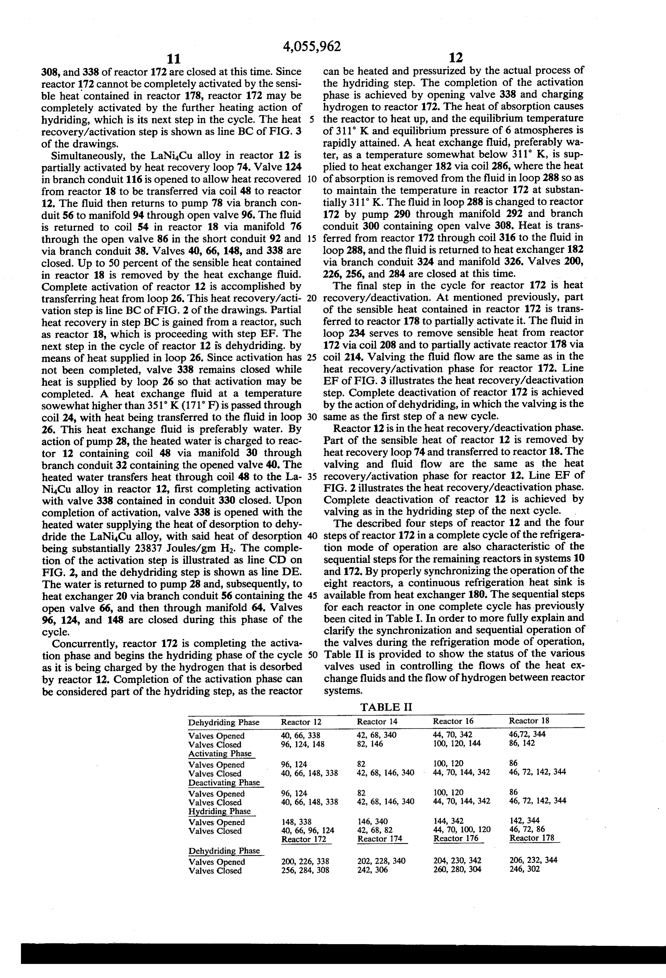
TABLE II
Dehydriding Phase Reactor 12 Reactor 14 Reactor 16 Reactor 18
Valves Opened 40, 66,338 42, 68,340 44, 70, 342 46,72, 344
Valves Closed 96, 124, 148 82, 146 100, 120, 144 86, 142
Activating Phase
Valves Opened 96, 124 82 100, 120 86
Valves Closed 40, 66, 148,338 42, 68, 146, 340 44, 70, 144, 342 46, 72, 42, 344 Deactivating Phase
Valves Opened 96, 124 82 100, 120 86
Valves Closed 40, 66, 148,338 42, 68, 146, 340 44, 70, 144, 342 46, 72, 142, 344 Hydriding Phase
Valves Opened 148,338 146, 340 144, 342 142, 344
Valves Closed 40, 66, 96, 124 42, 68,82 44, 70, 100, 120 46, 72, 86
Reactor 172 Reactor 174 Reactor 176 Reactor 178
Dehydriding Phase
Valves Opened 200, 226,338 202, 228, 340 204, 230, 342 206, 232, 344 Valves Closed 256, 284, 308 242, 306 260, 280, 304 246, 302
Page 10
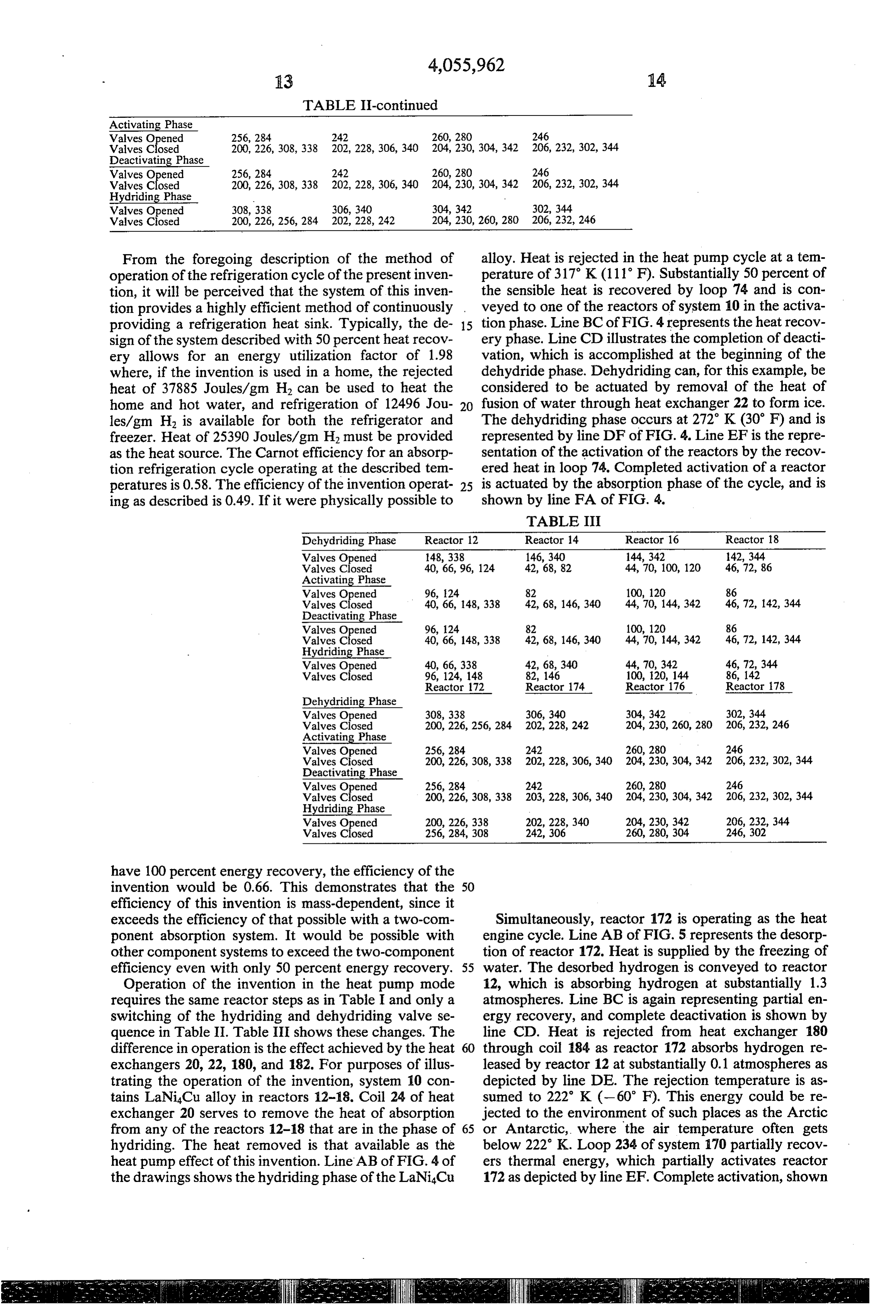
TABLE II-continued
Activating Phase
Valves Opened 256,284 242 260, 280 246
Valves Closed 200, 226, 308,338 202, 228, 306, 340 204, 230, 304, 342 206, 232, 302, 344 Deactivating Phase
Valves Opened 256, 284 242 260, 280 246
Valves Closed 200, 226, 308,338 202, 228, 306, 340 204, 230, 304, 342 206, 232, 302, 344 Hydriding Phase
Valves Opened 308,338 306, 340 304, 342 302, 344
From the foregoing description of the method of alloy. Heat is rejected in the heat pump cycle at a tem operation of the refrigeration cycle of the present inven perature of 317° K (111 F). Substantially 50 percent of tion, it will be perceived that the system of this inven the sensible heat is recovered by loop 74 and is con tion provides a highly efficient method of continuously . veyed to one of the reactors of system 10 in the activa providing a refrigeration heat sink. Typically, the de 15 tion phase. Line BC of FIG. 4 represents the heat recov sign of the system described with 50 percent heat recov ery phase. Line CD illustrates the completion of deacti ery allows for an energy utilization factor of 1.98 vation, which is accomplished at the beginning of the where, if the invention is used in a home, the rejected dehydride phase. Dehydriding can, for this example, be heat of 37885 Joules/gm H2 can be used to heat the considered to be actuated by removal of the heat of home and hot water, and refrigeration of 12496 Jou 20 fusion of water through heat exchanger 22 to form ice. les/gm H is available for both the refrigerator and The dehydriding phase occurs at 272K (30 F) and is freezer. Heat of 25390 Joules/gm H. must be provided represented by line DF of FIG. 4. Line EF is the repre as the heat source. The Carnot efficiency for an absorp sentation of the activation of the reactors by the recov tion refrigeration cycle operating at the described tem ered heat in loop 74. Completed activation of a reactor peratures is 0.58. The efficiency of the invention operat 25 is actuated by the absorption phase of the cycle, and is ing as described is 0.49. If it were physically possible to shown by line FA of FIG. 4.
TABLE III
Dehydriding Phase Reactor 12 Reactor 14 Reactor 16 Reactor 18 Valves Opened 148, 338 146, 340 144, 342 142, 344 Valves Closed 40, 66, 96, 124 42, 68,82 44, 70, 100, 120 46, 72, 86 Activating Phase
Valves Opened 96, 24 82 100, 120 86
Valves Closed 40, 66, 148,338 42, 68, 146, 340 44, 70, 144, 342 46, 72, 142, 344 Deactivating Phase -
Valves Opened 96, 124 82 100, 120 86
Valves Closed 40, 66, 148,338 42, 68, 146, 340 44, 70, 44, 342 46, 72, 142, 344 Hydriding Phase
Valves Opened 40, 66,338 42, 68, 340 44, 70, 342 46, 72,344 Valves Closed 96, 124, 148 82, 146 100, 120, 144 86, 142 Reactor 172 Reactor 174 Reactor 176 Reactor 178
Dehydriding Phase
Valves Opened 308,338 306, 340 304, 342 302, 344 Valves Closed 200,226, 256, 284 202, 228, 242 204, 230, 260, 280 206, 232, 246 Activating Phase
Valves Opened 256, 284 242 260, 280 246
Valves Closed 200, 226, 308, 338 202, 228, 306, 340 204, 230, 304, 342 206, 232, 302, 344 Deactivating Phase
Valves Opened 256, 284 242 260,280 246
Valves Closed 200, 226,308,338 203, 228, 306, 340 204, 230, 304, 342 206, 232, 302, 344 Hydriding Phase
Valves Opened 200, 226, 338 202, 228, 340 204, 230, 342 206, 232, 344 Valves Closed 256, 284, 308 242, 306 260, 280, 304 246, 302
have 100 percent energy recovery, the efficiency of the invention would be 0.66. This demonstrates that the 50 efficiency of this invention is mass-dependent, since it exceeds the efficiency of that possible with a two-com Simultaneously, reactor 172 is operating as the heat ponent absorption system. It would be possible with engine cycle. Line AB of FIG. 5 represents the desorp other component systems to exceed the two-component tion of reactor 172. Heat is supplied by the freezing of efficiency even with only 50 percent energy recovery. 55 water. The desorbed hydrogen is conveyed to reactor Operation of the invention in the heat pump mode 12, which is absorbing hydrogen at substantially 1.3 requires the same reactor steps as in Table I and only a atmospheres. Line BC is again representing partial en switching of the hydriding and dehydriding valve se ergy recovery, and complete deactivation is shown by quence in Table II. Table III shows these changes. The line CD. Heat is rejected from heat exchanger 180 difference in operation is the effect achieved by the heat 60 through coil 184 as reactor 172 absorbs hydrogen re exchangers 20, 22, 180, and 182. For purposes of illus leased by reactor 12 at substantially 0.1 atmospheres as trating the operation of the invention, system 10 con depicted by line DE. The rejection temperature is as tains LaNi4Cu alloy in reactors 12-18. Coil 24 of heat sumed to 222" K (-60 F). This energy could be re exchanger 20 serves to remove the heat of absorption jected to the environment of such places as the Arctic from any of the reactors 12-18 that are in the phase of 65 or Antarctic, where the air temperature often gets hydriding. The heat removed is that available as the below 222 K. Loop 234 of system 170 partially recov heat pump effect of this invention. Line AB of FIG. 4 of ers thermal energy, which partially activates reactor the drawings shows the hydriding phase of the LaNi4Cu 172 as depicted by line EF. Complete activation, shown
Page 11
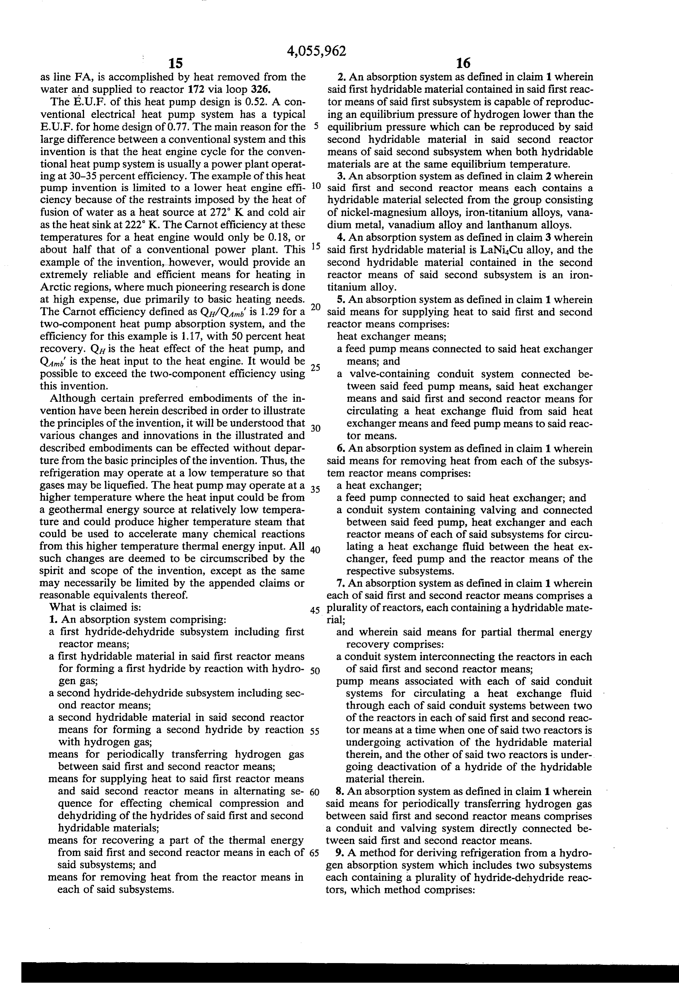
as line FA, is accomplished by heat removed from the 2. An absorption system as defined in claim 1 wherein water and supplied to reactor 172 via loop 326. said first hydridable material contained in said first reac The E.U.F. of this heat pump design is 0.52. A con tor means of said first subsystem is capable of reproduc ventional electrical heat pump system has a typical ing an equilibrium pressure of hydrogen lower than the E.U.F. for home design of 0.77. The main reason for the equilibrium pressure which can be reproduced by said large difference between a conventional system and this second hydridable material in said second reactor invention is that the heat engine cycle for the conven means of said second subsystem when both hydridable tional heat pump system is usually a power plant operat materials are at the same equilibrium temperature. ing at 30-35 percent efficiency. The example of this heat 3. An absorption system as defined in claim 2 wherein pump invention is limited to a lower heat engine effi O said first and second reactor means each contains a ciency because of the restraints imposed by the heat of hydridable material selected from the group consisting fusion of water as a heat source at 272 K and cold air of nickel-magnesium alloys, iron-titanium alloys, vana as the heat sink at 222 K. The Carnot efficiency at these dium metal, vanadium alloy and lanthanum alloys. temperatures for a heat engine would only be 0.18, or 4. An absorption system as defined in claim 3 wherein about half that of a conventional power plant. This 15 said first hydridable material is LaNi4Cu alloy, and the example of the invention, however, would provide an second hydridable material contained in the second extremely reliable and efficient means for heating in reactor means of said second subsystem is an iron Arctic regions, where much pioneering research is done titanium alloy.
at high expense, due primarily to basic heating needs. 5. An absorption system as defined in claim 1 wherein The Carnot efficiency defined as Q/Q is 1.29 for a said means for supplying heat to said first and second two-component heat pump absorption system, and the reactor means comprises:
efficiency for this example is 1.17, with 50 percent heat heat exchanger means;
recovery. Q is the heat effect of the heat pump, and a feed pump means connected to said heat exchanger Qat is the heat input to the heat engine. It would be 25 means; and possible to exceed the two-component efficiency using a valve-containing conduit system connected be this invention. tween said feed pump means, said heat exchanger Although certain preferred embodiments of the in means and said first and second reactor means for vention have been herein described in order to illustrate circulating a heat exchange fluid from said heat the principles of the invention, it will be understood that 30 exchanger means and feed pump means to said reac various changes and innovations in the illustrated and tOr means.
described embodiments can be effected without depar 6. An absorption system as defined in claim 1 wherein ture from the basic principles of the invention. Thus, the said means for removing heat from each of the subsys refrigeration may operate at a low temperature so that ten reactor means comprises:
gases may be liquefied. The heat pump may operate at a 35 a heat exchanger;
higher temperature where the heat input could be from a feed pump connected to said heat exchanger; and a geothermal energy source at relatively low tempera a conduit system containing valving and connected ture and could produce higher temperature steam that between said feed pump, heat exchanger and each could be used to accelerate many chemical reactions reactor means of each of said subsystems for circu from this higher temperature thermal energy input. All 40 lating a heat exchange fluid between the heat ex such changes are deemed to be circumscribed by the changer, feed pump and the reactor means of the spirit and scope of the invention, except as the same respective subsystems. may necessarily be limited by the appended claims or 7. An absorption system as defined in claim 1 wherein reasonable equivalents thereof. each of said first and second reactor means comprises a What is claimed is: 45 plurality of reactors, each containing a hydridable mate 1. An absorption system comprising: rial;
a first hydride-dehydride subsystem including first and wherein said means for partial thermal energy reactor means; recovery comprises:
a first hydridable material in said first reactor means a conduit system interconnecting the reactors in each for forming a first hydride by reaction with hydro 50 of said first and second reactor means; gen gas, pump means associated with each of said conduit a second hydride-dehydride subsystem including sec systems for circulating a heat exchange fluid ond reactor means; through each of said conduit systems between two a second hydridable material in said second reactor of the reactors in each of said first and second reac means for forming a second hydride by reaction 55 tor means at a time when one of said two reactors is with hydrogen gas; undergoing activation of the hydridable material means for periodically transferring hydrogen gas therein, and the other of said two reactors is under between said first and second reactor means; going deactivation of a hydride of the hydridable means for supplying heat to said first reactor means material therein.
and said second reactor means in alternating se 60 8. An absorption system as defined in claim 1 wherein quence for effecting chemical compression and said means for periodically transferring hydrogen gas dehydriding of the hydrides of said first and second between said first and second reactor means comprises hydridable materials; a conduit and valving system directly connected be means for recovering a part of the thermal energy tween said first and second reactor means. from said first and second reactor means in each of 65 9. A method for deriving refrigeration from a hydro said subsystems; and gen absorption system which includes two subsystems means for removing heat from the reactor means in each containing a plurality of hydride-dehydride reac each of said subsystems. tors, which method comprises:
Page 12
combining hydrogen gas with a first hydride-forming lower than P1, and combining the hydrogen gas in material in a reactor of one of said subsystems under the second hydride-forming material at a tempera conditions of a temperature, T, and a pressure, Pl, ture, T, substantially lower than T2, and a pressure, such that a first hydride saturated with, and in equi Ps, slightly lower than P;
librium with, hydrogen gas is formed, as the thus partially heating the first and second hydrides at con combined hydrogen gas is desorbed from a second stant volume by recovering heat from a reactor in hydride in a reactor of the second subsystem at a their respective systems;
refrigeration temperature, T, lower than Ti, and a further heating the first hydride by absorption; pressure, P, slightly greater than P, wherein the heating the second hydride at constant volume to the heat necessary to desorb the second hydride is the O temperature, T, and pressure, P; and refrigeration load; cyclically repeating the foregoing steps, concurrently heating the first and second hydrides at 14. A method as defined in claim 13 wherein one constant volume by recovering sensible heat from a system of reactor means contains a first hydridable different reactor in their respective subsystems; material capable of producing an equilibrium pressure then 15 of hydrogen lower than a second hydridable material of further heating the first hydride at constant volume to the second system of reactor means with both materials a temperature, T, and a pressure, Ps, which are at the same equilibrium temperature, substantially higher than T and Pl; and 15. A method as defined in claim 14 wherein each further heating the second hydride at constant vol system of reactor means contains a hydridable material ume to a temperature, T, and a pressure slightly 20 selected from the group consisting of nickel-magnesium lower than P;
heating the first hydride to desorb hydrogen gas at a alloys, dium iron-titanium alloys, vanadium metal and vana alloys, and lanthanum alloys, temperature, T, and a pressure, P; 16. A method as defined in claim 15 wherein the said absorbing the last-mentioned desorbed hydrogen gas first hydridable material is LaNiCu alloy and the sec in the hydridable material derived from said second 25 ond hydridable material is an iron-titanium alloy. hydride;
concurrently cooling the first and second hydrides at gen17.absorption
A method for deriving refrigeration from a hydro system comprising:
constant volume by transferring heat to a reactor in establishing a first group of first reaction zones having each of the respective subsystems; a first hydridable material in at least one of said first further cooling the first hydride at constant volume 30 reaction zones, and a hydride formed from said first by a heat exchange fluid; hydridable material in another of said first reaction cooling the second hydride by dehydriding the sec ond hydride by desorption of hydrogen therefrom; Zones;
and establishing a second group of second reaction zones cyclically repeating the foregoing steps. 35 having a second hydridable material in at least one 10. A method as defined in claim 9 wherein one sys of said second reaction zones, and a hydride formed tem of reactor means contains a first hydridable mate from said second hydridable material in at least one rial capable of producing an equilibrium pressure of other of said second reaction zones, said second hydrogen lower than a second hydridable material of hydridable material having a capability of produc the second system of reactor means with both materials 40 ing an equilibrium pressure of hydrogen higher than at the same equilibrium temperature. the equilibrium pressure of hydrogen produced by 11. A method as defined in claim 10 wherein each said first hydridable material in said first reaction system of reactor means contains a hydridable material zones when both said first and second hydridable selected from the group consisting of nickel-magnesium materials are at the same equilibrium temperature; alloys, iron-titanium alloys, vanadium metal and vana 45 transferring heat from a refrigeration medium to the dium alloys, and lanthanum alloys. one of said second reaction zones containing the 12. A method as defined in claim 11 wherein the said hydride of said second hydridable material to de first hydridable material is LaNiCu alloys and the sec sorb hydrogen gas therefrom at a refrigeration tem ond hydridable material is an iron-titanium alloy. perature T, and in a pressure P, wherein the heat 13. A method for deriving a heat pump effect from a 50 necessary to desorb hydrogen gas from the hydride hydrogen absorption system comprising: of the second hydridable material is the refrigera combining hydrogen gas with a first hydride-forming tion load;
material under conditions of temperature, T1, and transferring desorbed hydrogen gas from said second pressure, P, such that a first hydride saturated with reaction zone containing a hydride of said second and in equilibrium with hydrogen gas is formed as 55 hydridable material undergoing desorption of the the hydrogen gas is desorbed from a second hydride hydrogen gas from the hydride therein by the cool at a temperature, T2, substantially lower than T1, ing of said refrigeration medium, to the first hydri and a pressure, P, slightly greater than P1, wherein dable material in said one of said first reaction the heat of absorption of the first hydride is the heat Zones;
pump effect; combining said transferred hydrogen gas with said partial cooling of the first and second hydrides at first hydridable material in said one of said first constant volume by transferring heat to a reactor in reaction zones under conditions of a temperature, each of their respective systems; T1, and a pressure, P1, which is less than P, such further cooling the first hydride by desorption; that a hydride of said first hydridable material in cooling the second hydride at constant volume by a 65 said one first reaction zone which is saturated with, heat exchange fluid; m and in equilibrium with, hydrogen gas is formed heating the first hydride to desorb hydrogen gas at a with concurrent exothermal release of thermal en temperature, T2, and a pressure, P4, substantially ergy; then
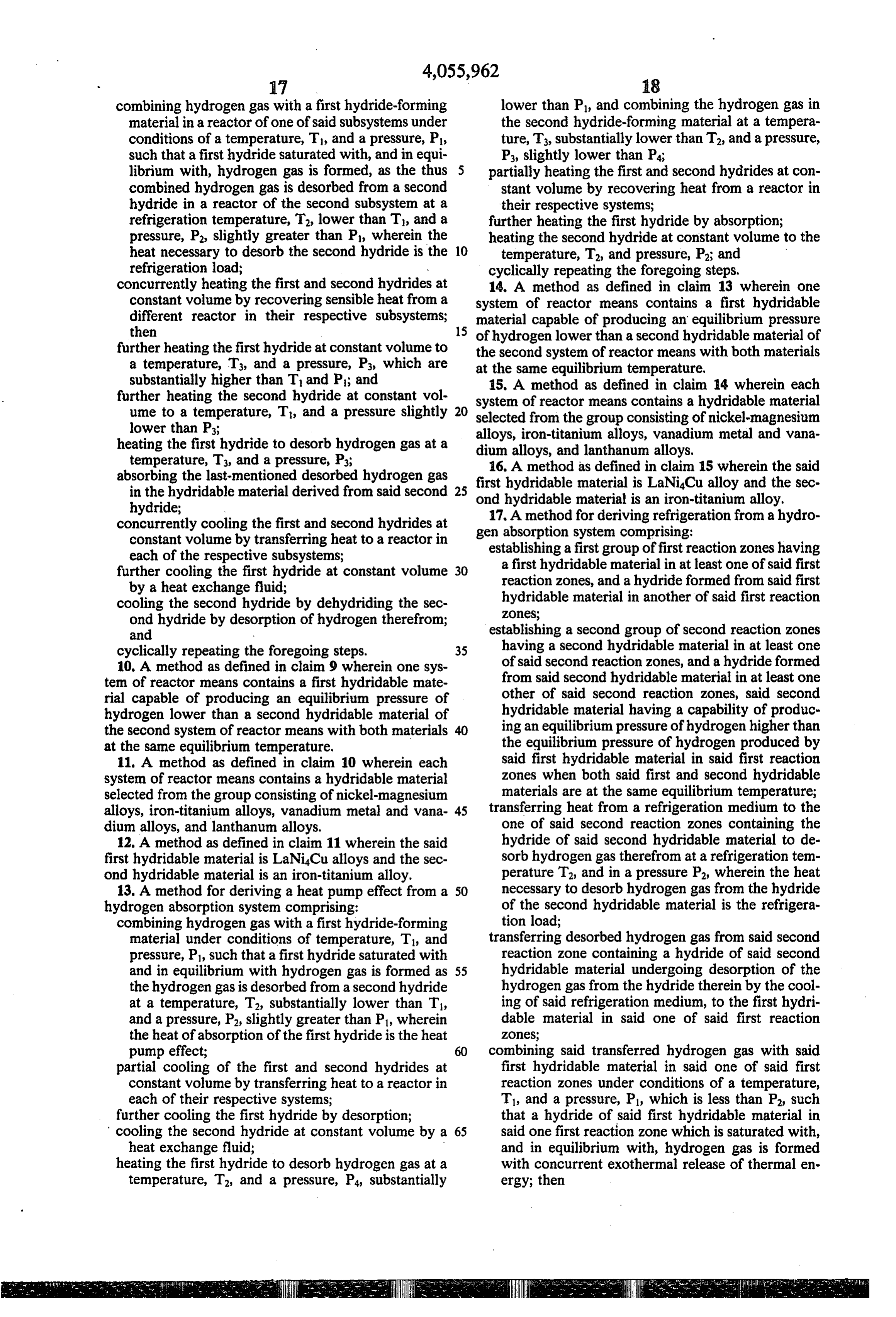
Page 13
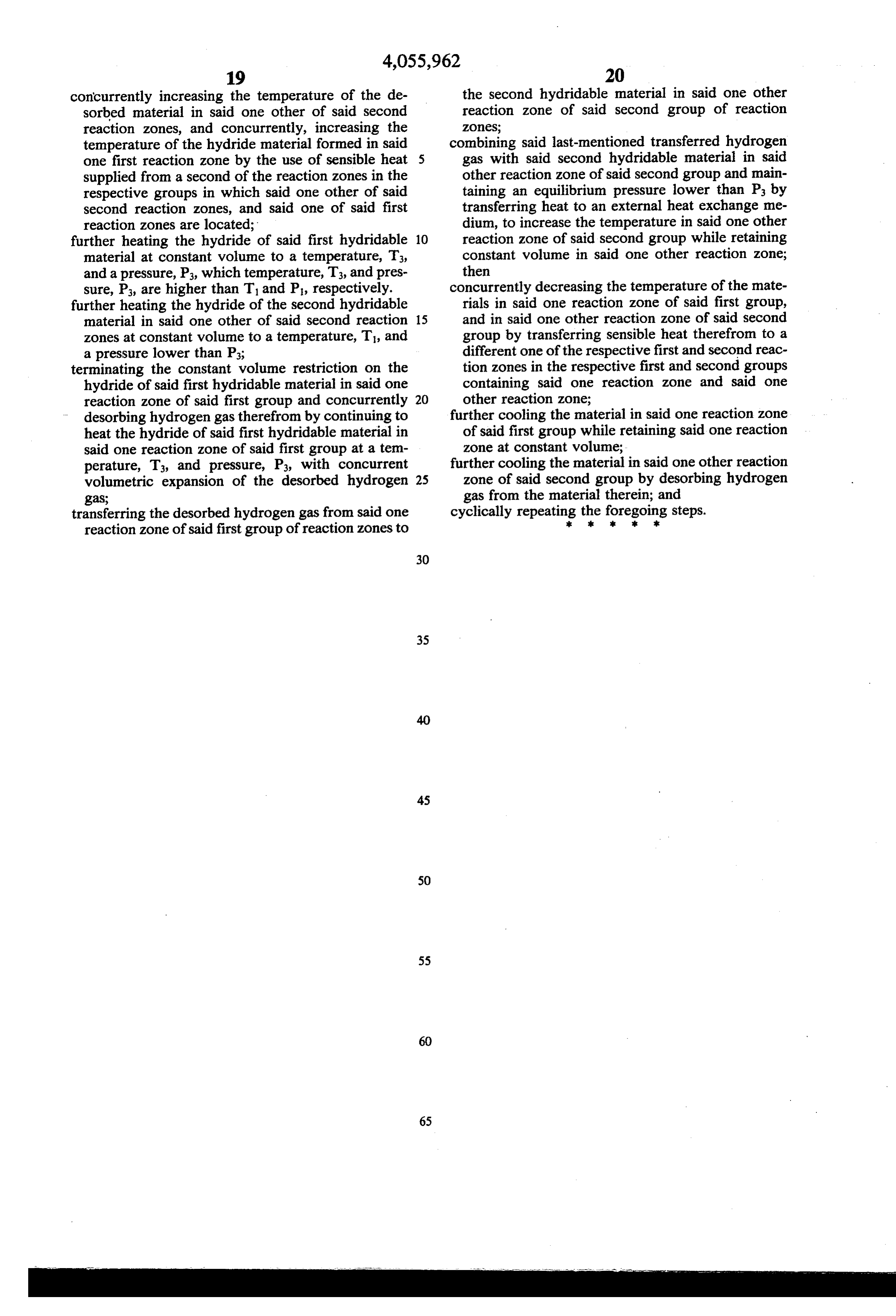
concurrently increasing the temperature of the de the second hydridable material in said one other sorbed material in said one other of said second reaction zone of said second group of reaction reaction zones, and concurrently, increasing the Zones;
temperature of the hydride material formed in said combining said last-mentioned transferred hydrogen one first reaction zone by the use of sensible heat 5 gas with said second hydridable material in said supplied from a second of the reaction zones in the other reaction zone of said second group and main respective groups in which said one other of said taining an equilibrium pressure lower than Ps by second reaction zones, and said one of said first transferring heat to an external heat exchange me reaction zones are located; dium, to increase the temperature in said one other further heating the hydride of said first hydridable 10 reaction zone of said second group while retaining material at constant volume to a temperature, T, constant volume in said one other reaction zone; and a pressure, P., which temperature, T3, and pres then sure, P., are higher than T and P, respectively. concurrently decreasing the temperature of the mate further heating the hydride of the second hydridable rials in said one reaction zone of said first group, material in said one other of said second reaction 15 and in said one other reaction zone of said second zones at constant volume to a temperature, T, and group by transferring sensible heat therefrom to a a pressure lower than Ps; different one of the respective first and second reac terminating the constant volume restriction on the tion zones in the respective first and second groups hydride of said first hydridable material in said one containing said one reaction zone and said one reaction zone of said first group and concurrently 20 other reaction zone;
desorbing hydrogen gas therefrom by continuing to further cooling the material in said one reaction zone heat the hydride of said first hydridable material in of said first group while retaining said one reaction said one reaction zone of said first group at a tem zone at constant volume;
perature, T3, and pressure, P3, with concurrent further cooling the material in said one other reaction volumetric expansion of the desorbed hydrogen 25 zone of said second group by desorbing hydrogen gas; gas from the material therein; and transferring the desorbed hydrogen gas from said one cyclically repeating the foregoing steps.
reaction zone of said first group of reaction zones to
Page 14
UNITED STATES PATENT OFFICE Page l of 2
(CERTIFICATE OF CORRECTION
Patent No. 4, O55, 962 Dated November 1, 1977 Inventor (s) Lynn E. Terry
It is certified that error appears in the above-identified patent and that said Letters Patent are hereby corrected as shown below:
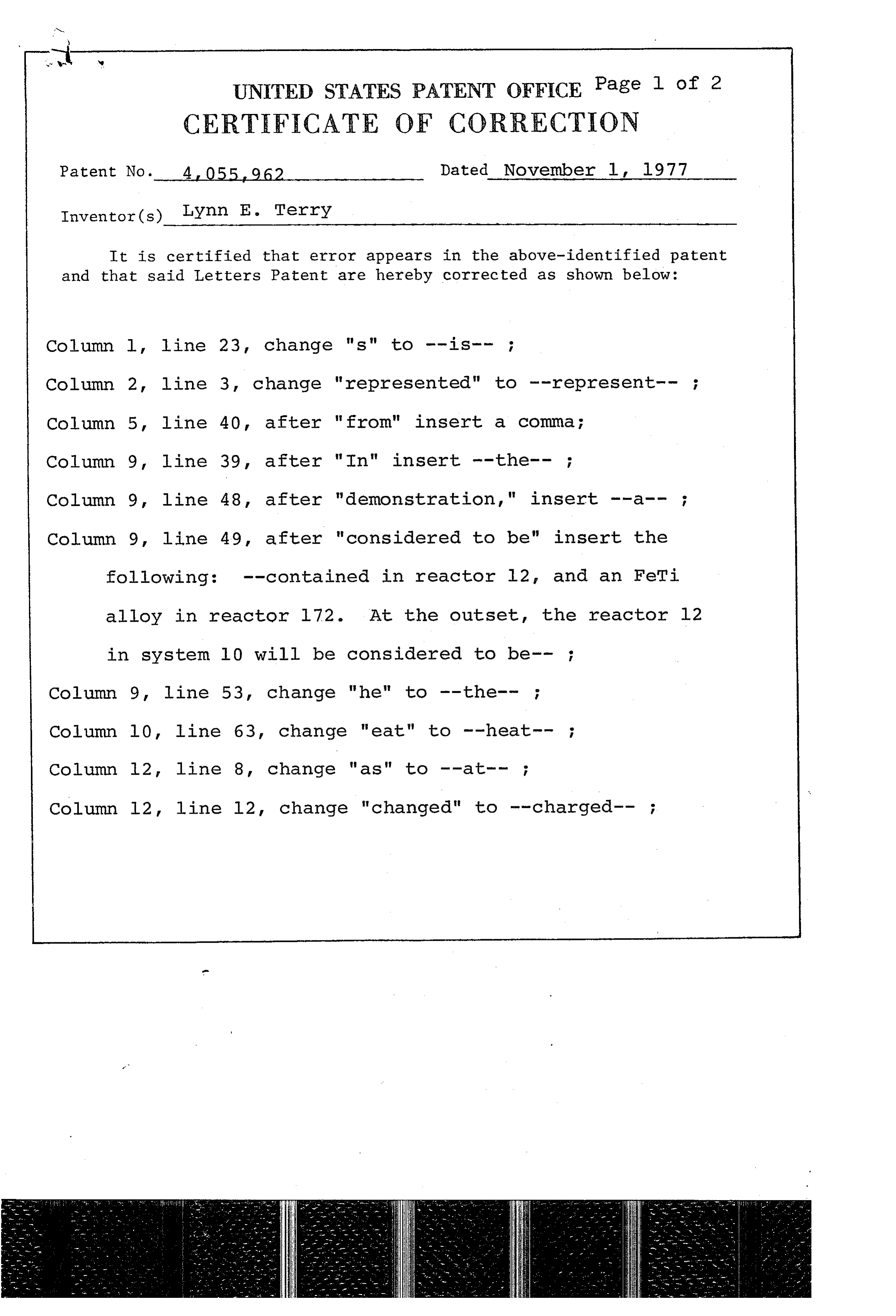
Column l, line 23, change "s" to --is-- ;
Column 2, line 3, change "represented" to --represent-- ; Column 5, line 40, after "from" insert a comma; Column 9 line 39, after "In" insert --the-- Column 9, line 48, after "demonstration," insert --a-- ; Column 9, line 49, after "considered to be" insert the following: --contained in reactor l2, and an FeTi alloy in reactor l72. At the outset, the reactor l2 in system 10 will be considered to be--
Column 9, line 53, change "he" to --the-- ;
Column l0, line 63, change "eat" to --heat-- ; Column l2, line 8, change "as" to --at-- ;
Column l2, line l2, change "changed" to -- charged-- ;
Page 15
UNITED STATES PATENT OFFICE
Page 2 of 2
CERTIFICATE OF CORRECTION
Patent No. 4,055, 962 Dated November 1, 1977 Inventor(s) Lynn E. Terry
It is certified that error appears in the above-identified patent and that said Letters Patent are hereby corrected as shown below:
Column l2, line 20, change "At" to --As-- ;
Column 12, line 25, after "Valving", delete "the" and insert --and-- ;
Column l6, line l4, after "vanadium" change "alloy" to
eigned and Sealed this
Fourteenth Day of March 1978
(SEAL
RUTH C. MASON LUTRELLE F. PARKER
Attesting Officer Acting Commissioner of Patents and Trademarks
Provenance
- Collection
- Cited prior art
- Original PDF
- patentimages.storage.googleapis.com →
- Filed
- 1976-08-18
- Pages
- 15
- Method
- pdftotext (the PDF's own text layer) + pdftoppm 300dpi page scans
- Source
- Google Patents bibliographic record
- Granted
- 1977-11-01
- Inventors
- Lynn E. Terry
- Transcribed from
- patentimages.storage.googleapis.com →