patent · US5728464
Hydrogen generation pelletized fuel
17 March 1998
Page 1 — bibliographic record
United States Patent (19) 11 Patent Number: 5,728,464 Checketts 45) Date of Patent: Mar. 17, 1998
54 HYDROGEN GENERATION PELLETIZED The Kirk Othmer Encyclopedia Of Chemical Technology FUEL Third Edition, vol. 21 pp. 181-203 "Sodium and Sodium
76 Inventor: Jed H. Checketts, 137 W. Goltz Ave.,
Salt Lake City, Utah 84101
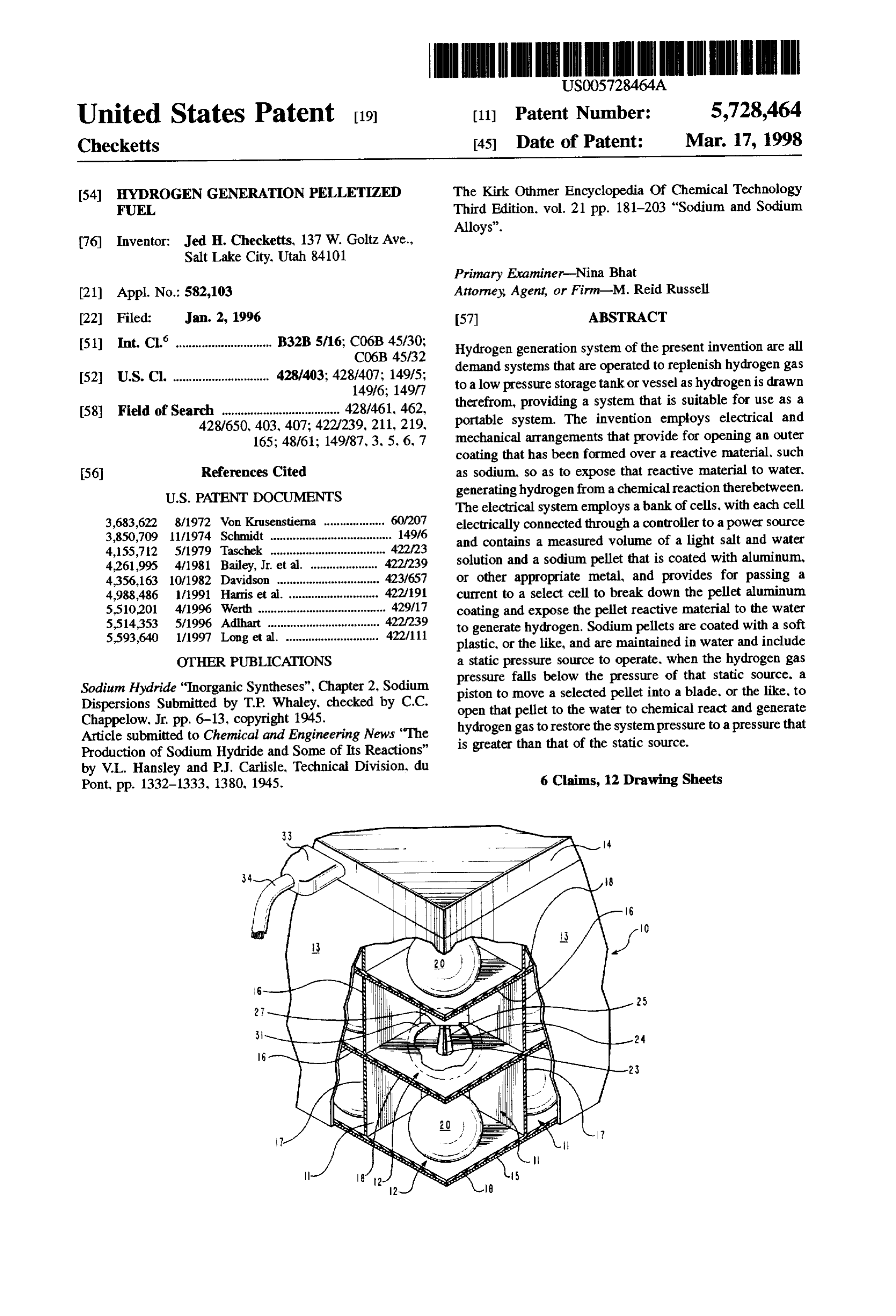
Primary Examiner-Nina Bhat (21) Appl. No.: 582,103 Attorney, Agent, or Firm-M. Reid Russell 22 Filed: Jan. 2, 1996 57 ABSTRACT (51) Int. Cl. ........................... B32B5/16; C06B 45/30; Hydrogen generation system of the present invention are all
demand systems that are operated to replenish hydrogen gas 52 U.S. Cl. ............................. 428/403; 428/407: 149/5; to a low pressure storage tank or vessel as hydrogen is drawn
(58) Field of Search ..................................... 428/461, 462, therefrom, providing a system that is suitable for use as a 428/650, 403, 407; 422/239, 211, 219, portable system. The invention employs electrical and 165; 48/61; 149/87, 3, 5, 6, 7 mechanical arrangements that provide for opening an outer coating that has been formed over a reactive material, such 56 References Cited as sodium, so as to expose that reactive material to water,
The electrical system employs a bank of cells, with each cell 3,683,622 8/1972 Won Krusenstierna ................... 60/207 electrically connected through a controller to a power source 3,850,709 11/1974 Schmidt ...................................... 149/6 and contains a measured volume of a light salt and water 4,155,72 5/1979 Taschek .................................... 422/23 4,261,995 4/1981 Bailey, Jr. et al. ... 422/239 solution and a sodium pellet that is coated with aluminum, 4,356,163 10/1982 Davidson ......... ... 423/657 or other appropriate metal, and provides for passing a 4,988,486 1/1991 Harris et al. . ... 422/91 current to a select cell to break down the pellet aluminum 5,510,201 4/1996 Werth ........... ... 429/17 coating and expose the pellet reactive material to the water 5,514,353 5/1996 Adhart ........ ... 422?239 to generate hydrogen. Sodium pellets are coated with a soft 5.593,640 l/1997 Long et al. ............................. 422/11 plastic, or the like, and are maintained in water and include OTHER PUBLICATIONS a static pressure source to operate, when the hydrogen gas pressure falls below the pressure of that static source, a
Sodium Hydride "Inorganic Syntheses", Chapter 2, Sodium piston to move a selected pellet into a blade, or the like. to Dispersions Submitted by T.P. Whaley, checked by C.C. open that pellet to the water to chemical react and generate Chappelow, Jr. pp. 6-13, copyright 1945. hydrogen gastorestore the system pressure to a pressure that Article submitted to Chemical and Engineering News "The is greater than that of the static source. Production of Sodium Hydride and Some of Its Reactions" by V.L. Hansley and P.J. Carlisle, Technical Division, du
Pont, pp. 1332-1333. 1380, 1945. 6 Claims, 12 Drawing Sheets
Page 2
Drawing sheet — no readable text.
Page 3
Drawing sheet — no readable text.
Page 4
Drawing sheet — no readable text.
Page 5
Drawing sheet — no readable text.
Page 6
Drawing sheet — no readable text.
Page 7
Drawing sheet — no readable text.
Page 8
Drawing sheet — no readable text.
Page 9
Drawing sheet — no readable text.
Page 10
Drawing sheet — no readable text.
Page 11
Drawing sheet — no readable text.
Page 12
Drawing sheet — no readable text.
Page 13
Drawing sheet — no readable text.
Page 14
HYDROGEN GENERATION PELLETZE) membrane system by employing a pair of membranes to FUEL separate the metal hydride and water with a dead space BACKGROUND OF THE INVENTON therebetween. While, with a use of two membranes, a likelihood of a membrane tearing as would create a cata 1. Field of the Invention strophic failure is somewhat minimized, that danger is not This invention relates to coated alkali metal or metal eliminated. Further, the inherent problems of membrane hydride pellets and their use in demand type hydrogen porosity and metal hydride caking have not been addressed generation systems for selectively opening a pellet or pellets in this '955 patent. The present invention is distinct there to water for providing a controlled generation of hydrogen. from in that, while it is also a demand system with hydrogen 2. Prior Art 10 gas produced as needed and involves a chemical reaction of It has long been recognized that hydrogen gas can be used an alkali metal or hydride metal and water, the invention as a fuel for internal combustion engines, fuel cells, and the provides for a selected exposure of pellets of the alkalimetal like. Where hydrogen has been produced commercially, as or hydride metal to water such that there is no possibility that for example, from a steam/colte process or as a by-product all the available pellet materials would be exposed to water from the chlor-alkali industry, to contain the produced gas 15 even in a tankrupture. Unique to the invention pellets of an that must initially be at high pressure, a very strong heavy alkali metal or hydride metal are formed as spheres, cubes, container is required to maintain a significant volume of gas, or other appropriate shape, that are encapsulated within a limiting a portable use. Similarly, to contain hydrogen in a shell or coating of a material that is impervious to water. The liquid state has also required a strong and therefore heavy coating provides a barrier to exposure of the pellet core even containment vessel, limiting use as a portable supply. Which 20 when the pellet is covered by a salt water solution and must problems of a requirement for a heavy strong container are be opened, dissolved, or otherwise penetrated for the pellet overcome by a demand system like that of the invention. material to react with water to form hydrogen. The invention An example of a production of hydrogen from a chemical provides for individually opening each pellet in turn to reaction of an alkali metal with water is shown in a patent expose the pellet core to water, generating hydrogen to meet to Davidson, U.S. Pat. No. 4356,163. The Davidson patent, 25 a demand. A preferred pellet coating or shell material is a however, does not show a coating of chemical spheres and metal such as aluminum to be dissolved when exposed to an their arrangement and use in a device for producing hydro electrical current, or a plastic, such as a high density gen on demand, that are like the embodiments of the polyethylene used where the pellet is split. So arranged, the invention, as set out herein. invention involves a demand system for both opening pellets A demand system of the invention is, of course, one where 30 to water as a need for hydrogen gas generation upon sensing the system produces hydrogen on a need basis. Such pro of a drop in hydrogen gas pressure below a set minimum, duced gas is at a low pressure thereby requiring only a and for capturing the hydrogen gas generated by the reaction nominally strong container to safely maintain it, enabling a of the pellet material and water.
practical installation of the system in a vehicle, or the like, Such hydrogen gas, under pressure, as is produced and that will use the produced hydrogen as a fuel. A desirability 35 maintained in the system of the invention can then be of such demand system has been recognized in patents to conveniently used as a fuel source. For example, a use of Taschek, U.S. Pat. No. 4.155.712 and to Bailey, Jr. etal, U.S. hydrogen as a fuel for an internal combustion engine, fuel Pat. No. 4,261,955. These patents, however, show systems cell, or the like, is shown in a patent to Von Krusenstierna, that are unlike the present invention. With the Taschekpatent U.S. Pat. No. 3,683.622. Heretofore, a practical light weight showing a system that includes a housing containing a chemical hydrogen generation system like that of the present membrane that is arranged to separate a water filled con invention that is arranged to function as a demand system tainer and a container of chunks or pellets of a metal hydride has not been known.
or alkali metal, with the water to slowly diffuse through the membrane. This diffusion is to be controlled by a pressure SUMMARY OF THE INVENTION differential as exists across the membrane. The system of the 45 It is a principal object of the present invention to provide, Taschek'712, as shown, is simple and apparently easy to as a fuel for a chemical hydrogen generation system, indi construct and, as the anticipated pressure of the gas pro vidual pellets that are formed of a reactive material such as duced would be low, could conceivably utilize a thin walled an alkali metal or metal hydride that, on contact with water, light weight gas holding tank appropriate for use in a portable system. While the Taschek'712 patent can be 50 produce Another hydrogen as a product of that reaction.
object of the present invention is to provide a interpreted as showing a demand system, in practice it would demand system including an arrangement to open a coating be unreliable as, in the event of a rupture to the membrane or shell of an individual pellet upon sensing a need for separating the water filled container and the container of generation of additional hydrogen alkali metal, all of the alkali metal would immediately be core to water to generate hydrogensogasasthat to expose that pellet is then contained exposed to the water, creating a rapid production of hydro 55 for use as a fuel.
gen and an overpressure condition. Such rapid hydrogen production would likely rupture the container causing a Another object of the present invention is to provide for release of hydrogen into the air, which release could poten loading a number of the coated pellets into the system tially result in an explosion. Further, as to system container or housing to be stored in water and providing for functioning, over time the speed of water vapor diffusion individually opening each pellet to expose it to water, through the membrane will vary as the membrane pores generating presence in hydrogen gas, upon a sensing of a minimum gas the container, the generated hydrogen increasing clog. Also, a metal hydride will tend, over time to cake, prohibiting a complete chemical reaction. For these and the gas volume and pressure therein for use as a fuel source. other reasons the system of the Taschek'712 patent cannot Another object of the present invention is to provide an be practically applied as a reliable portable system. 65 arrangement for, on demand, selectively exposing individual The subsequent '955 patent to Bailey, Jr. and Taschek alkali metal or metal hydride pellets, in turn. to water. seeks to solve the safety problems as are inherent in a single producing hydrogen gas as a product of the reaction to
Page 15
restore pressure within a storage tank so as to maintain a Which tank system includes a pressure sensing device for desired pressure range therein. monitoring internal tank pressure and transmitting that infor Still another object of the present invention is to provide mation to the electronic control system that is preferably a computer. With, upon a sensing of a hydrogen pressure for coating of individual alkalimetal or metal hydride pellets therein that is less than a set minimum, or a rapid change in with a material that is water impervious but can be easily and tank pressure, quickly opened or broken down in the presence of a dilute gas by selectingthea particular system provides for renewing hydrogen alkaline solution, to expose the reactive material to water, and passing a voltage to thatcell or cells of the bank of cells, cell or cells to disintegrate the producing hydrogen as a product of the chemical reaction. pellet covering material. The pellet material in each cell is Still another object of the present invention is to provide thereby exposed to and reacts with water, as set out above, for coating a reactive material pellet with aluminum, or like O producing hydrogen that is then passed from the individual metal, and providing a hydrogen generation system for cell to the storage tank, restoring the tank pressure to within containing the individual aluminum coated pellets in indi a range of desired tank pressures.
vidual cells, that each contain a water and light salt solution For the above embodiment, the pellet coating material is that, on receipt of a voltage, forms sodium hydroxide that 5 preferably aluminum that coats a sodium sphere coated, reacts with aluminum, disintegrating the aluminum cover such that when a voltage is passed into the light salt and and allowing the reactive material and water to chemically react to produce hydrogen gas that is stored at low pressure water solution, a sodium chloride electrolysis is set up that produces sodium hydroxide that will attack the aluminum in the system. coating. The coating is dissolved in a matter of seconds and Still another object of the present invention is to provide 20 the sodium sphere is exposed to the cell water, reacting for coating a reactive material pellet with a plastic material, therewith to produce hydrogen as a product of that reaction. such as a polyvinyl chloride coating, and providing a hydro Also, the sodium hydroxide and aluminum reaction itself gen generation system arranged for cutting open the pellet as produces hydrogen and accordingly, it is preferred that the by forcing a pellet through a knife or guillotine blade. sodium sphere contain a core of aluminum to react with a exposing the pellet core to water, generating hydrogen gas 25 product of the sodium and water reaction, sodium that is stored at low pressure in the system. hydroxide, releasing additional hydrogen and producing Still another object of the present invention is to provide sodium aluminate.
a system for chemically producing hydrogen, on demand, to The computer system of this embodiment both keeps maintain hydrogen gas as a fuel at low pressure within a track of the cells that have not been chemically reacted, and storage tank of the system, which, upon sensing a drop in 30 will project the number of cells that are needed to be reacted pressure in the storage tank, the system is operated to add to restore the tank system pressure to within a desired hydrogen gas from a reaction of a pellet of reactive material pressure range. The computer system can also provide a and Water. hydrogen user with a running total of the number or per Still another object of the present invention is to provide centage of cells that remain available for reaction, and the a hydrogen generation system that can be used as a portable 35 bank of cells is preferably arranged to be easily and quickly fuel source. removed, when expended, and replaced with a fully charged The present invention is a low pressure hydrogen genera system.
tion system operated on demand for supplying hydrogen gas Second and third embodiments of the invention that are for use as a fuel, the system to utilize pellets that are formed also low pressure hydrogen generation systems and are from a reactive material and include water impervious outer operated on demand, utilize coated reactive material pellets, coatings or shells formed thereover, with the system to with the pellet coating selected to be water impervious. A provide. upon sensing of a minimum pressure of hydrogen preferred pellet coating is a flexible plastic, such a high gas therein, for opening an individual pellet to expose the density polyethylene that provides to the pellet a durable pellet core to water, generating hydrogen to raise the system flexible water impervious coating. So arranged, the coated hydrogen gas pressure. 45 pellets that are preferably formed as spheres from a reactive In one embodiment of a hydrogen generation system of material that is an alkali metal, metal hydride or the like, the invention, the pellet of a reactive material, such as such as sodium, will float in water. The coated pellets are for sodium, is formed into a sphere, cube, or like shape, and is use in a closed housing that is at least partially filled with coated with an electrically conductive material, such as water to react with the pellet core to produce hydrogen that aluminum. The individual coated pellets are for positioning 50 may be contained within the same housing. The housing is in cells of a bank of individual cells that are each formed of arranged to receive a number of the coated pellets and a non-reactive material, such as steel. Each cell contains a includes a carousel arrangement that is turned on operation light salt and water solution and each pellet is formed of of a reactor piston to drive a pellet into a fixed reactor blade, sodium or another suitable alkali metal or metal hydride and splitting the pellet and positioning a following individual its electrically conductive coating material is non-reactive in 55 pellet into alignment with a tube or chamber open end. The the salt water. Each cell is connected to receive a voltage tube or chamber contains water. The pellet floats upwardly supplied thereto as controlled by an electronic control in, passing into a reactor chamber, to align with the reactor system, such as a computer, the coating material upon blade. Thereafter, where a need exists to produce additional receipt of the voltage to disintegrate in the presence of an hydrogen, a reactor piston is operated to drive the pellet into alkaline mixture such as that created when a voltage is the fixed reactor blade, spiting the aligned pellet in half. The passed into a light salt and water solution. With the disin reaction within the pellet halves reacts with the surrounding tegration of the aluminum coating, the pellet core material water and produces hydrogen gas. The coating from the reacts with the water in the cell to produce hydrogen gas as reacted pellet floats to the water surface. a product of that reaction. The produced hydrogen is vented The added hydrogen gas increases the gas pressure within to a tank system for storing the hydrogen at low pressure and 65 the housing that is compared against a static pressure source. connects to a system that utilizes hydrogen gas for fuel, such Thereafter, as the hydrogen gas is removed for use, the as an internal combustion engine, fuel cell, or the like. hydrogen gas pressure decreases to below the static pressure
Page 16
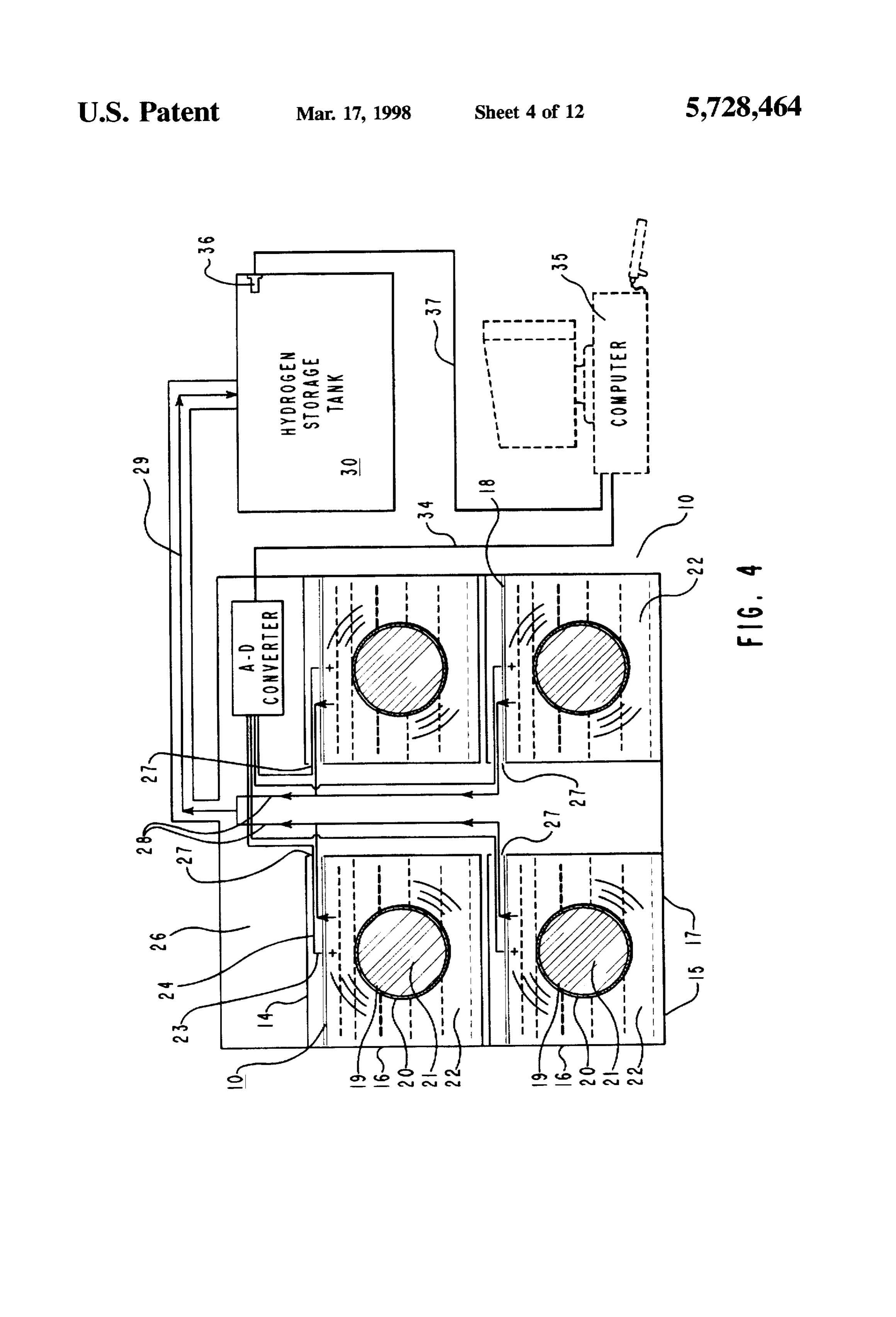
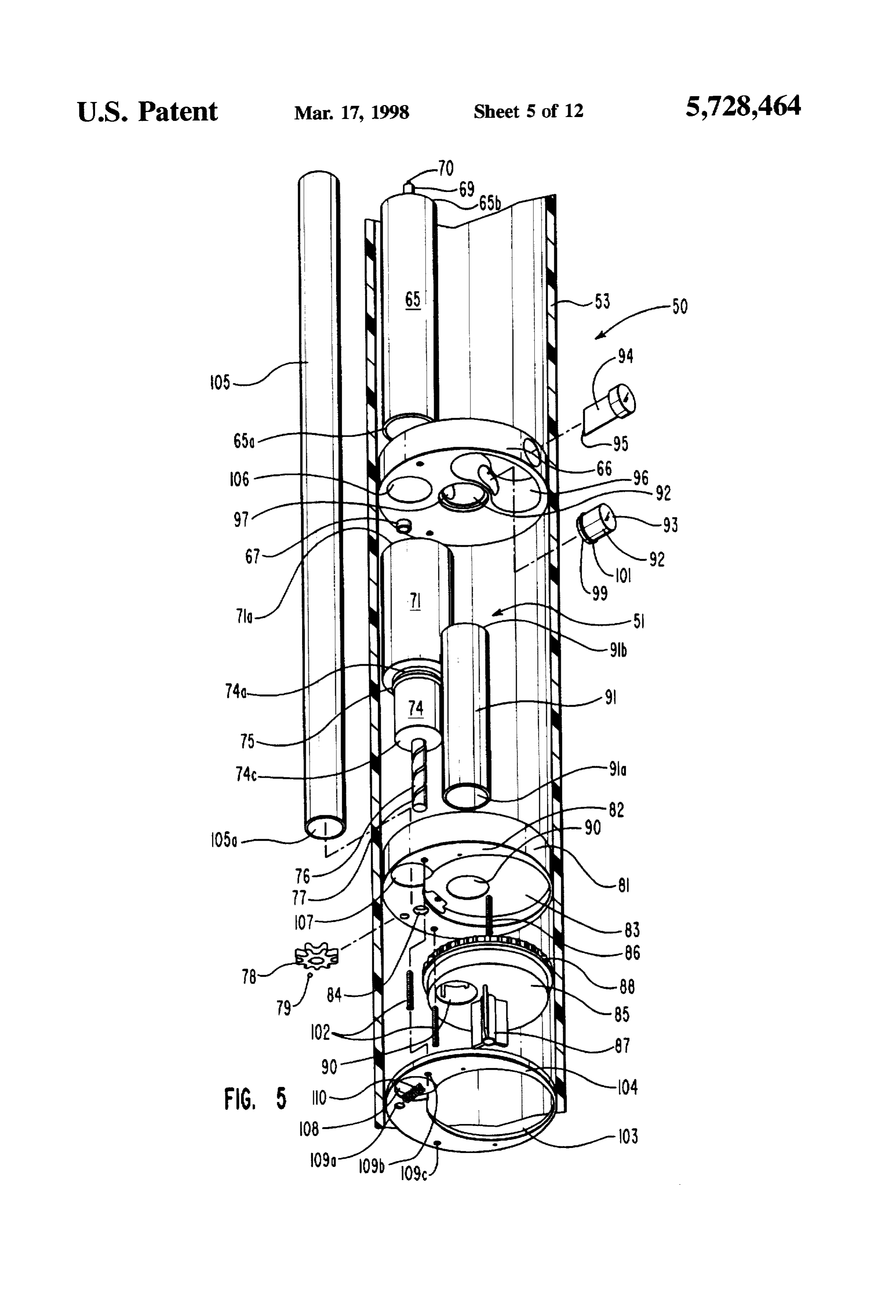
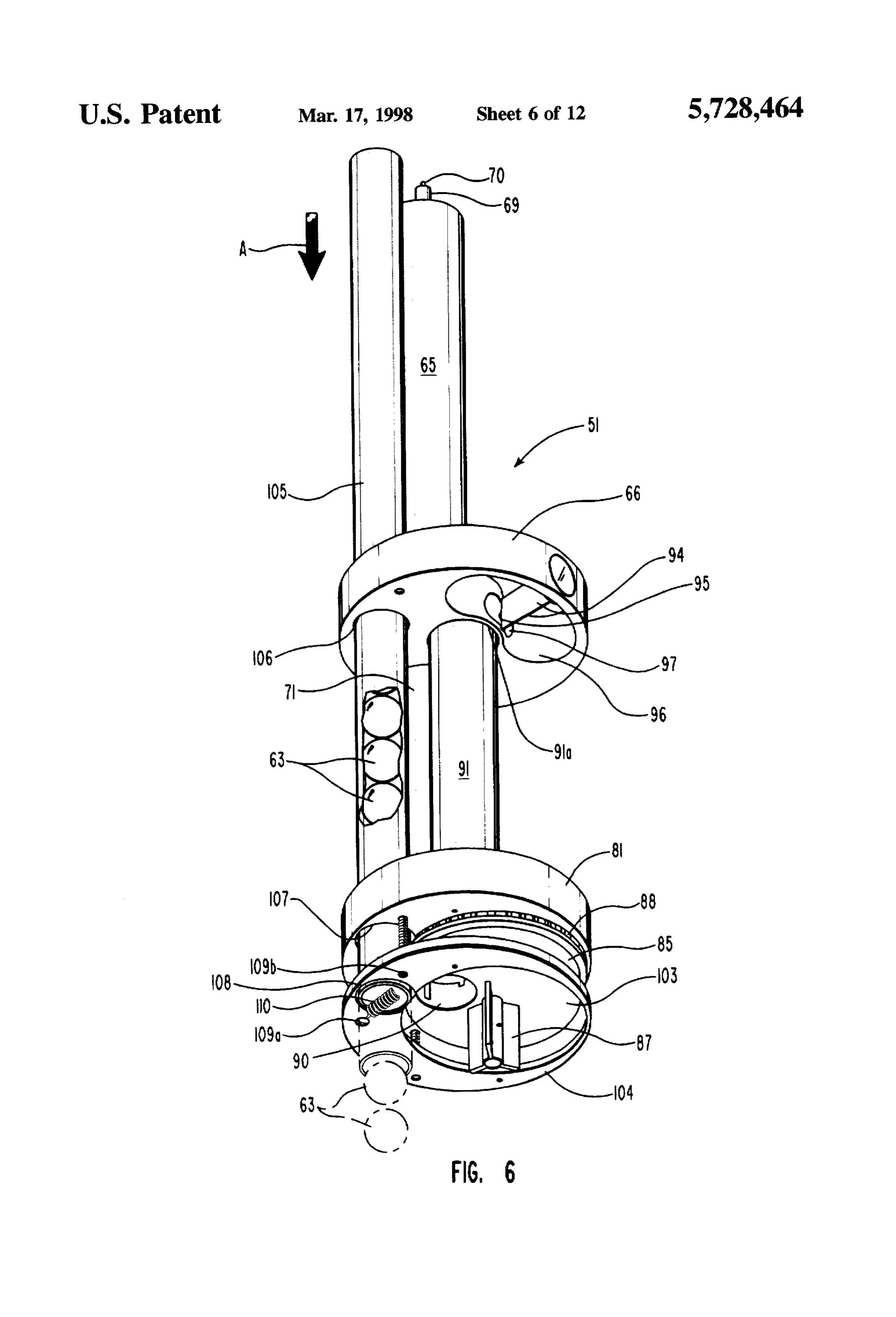
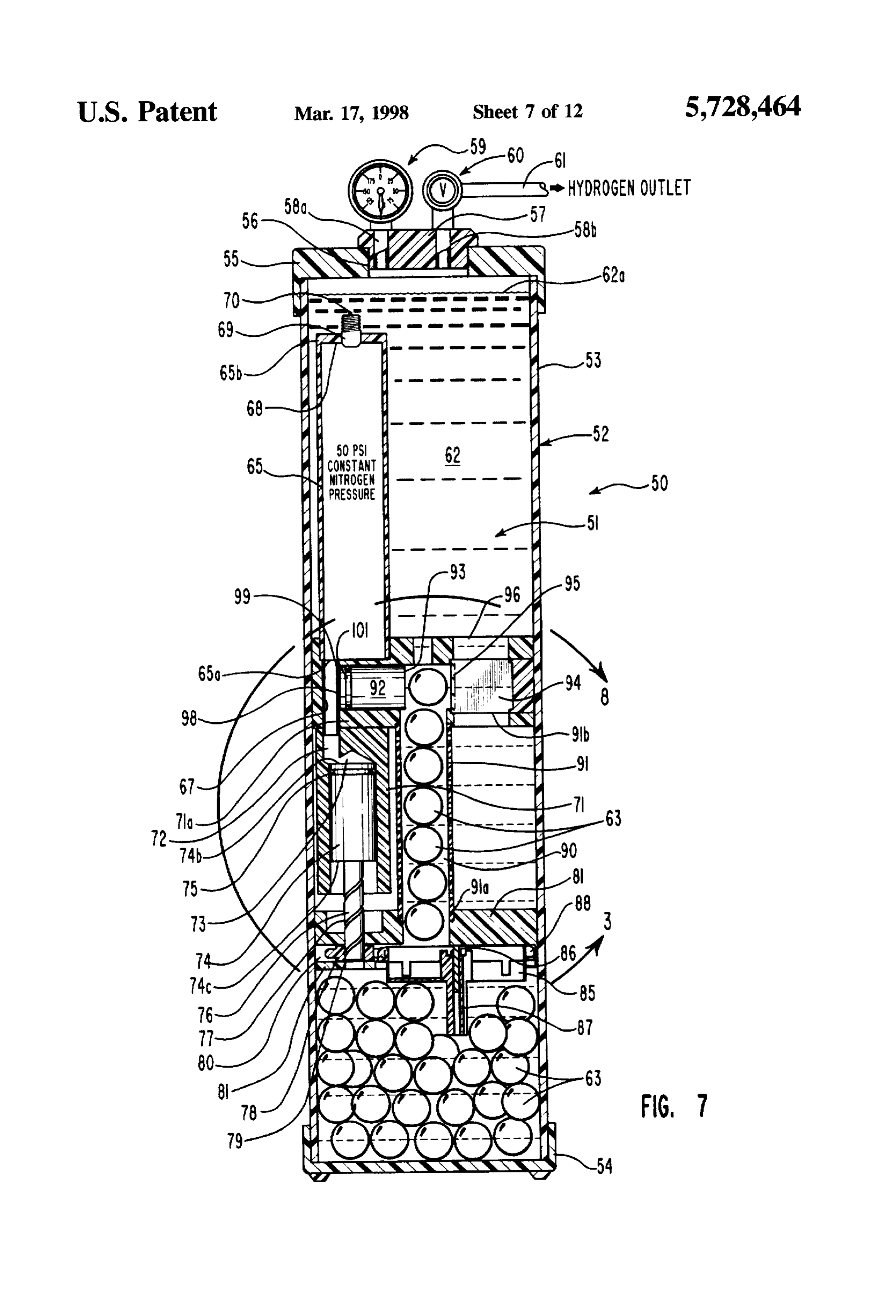
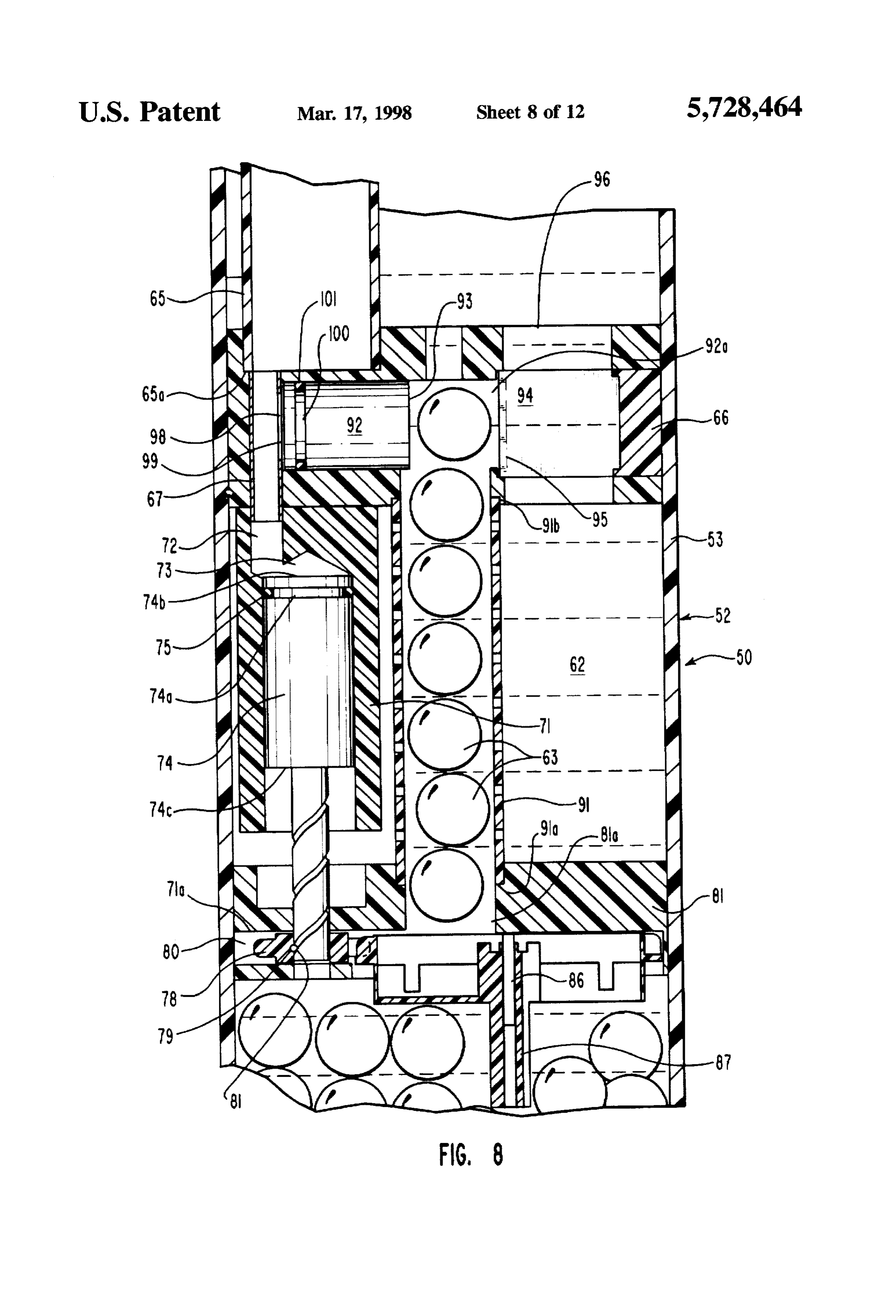
source whereat the static pressure source causes the reactor system of FIGS.5 and 6 fitted therein. showing the vessel or piston to be extended and a new pellet selected and posi tank filled with water and with a number of spherical pellets tioned for passage to the reaction chamber. The reactor shown essentially filling the bottom of the vessel or tank, piston urges a pellet into the reactor blade, with the split with a column of the spherical pellets shown floating pellet then generating hydrogen gas to increase the hydrogen upwardly in a feed tube, and showing a top spherical pellet gas pressure to above that of the static source, causing the shown aligned with a reactor piston that is operated to drive reaction piston to retract. a spherical pellet into a fixed reactor blade; Both the above set out system embodiments provide for FIG. 8 shows an enlarged sectional view taken within the replenishing hydrogen gas on a need or demand basis as line 7- 7 of FIG. 6;
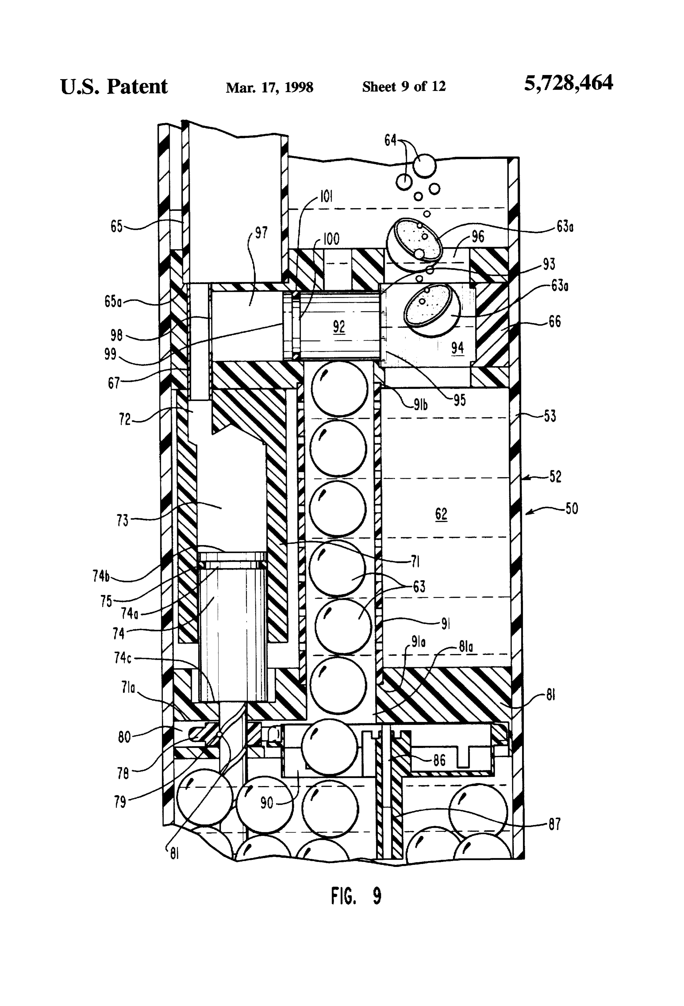
hydrogen gas is withdrawn for use, as for example, for O FIG. 9 shows the view of FIG. 8 after the reactor piston fueling an internal combustion engine or fuel cell. has extended to drive the spherical pellet into the reactor Accordingly, a low pressure of hydrogen gas only need be blade, cutting the spherical pellet in half, with the pellet maintained, allowing the vessel or container wherein the halves shown floating upwardly in the water, and showing hydrogen gas is generated and/or stored to be constructed bubbles being emitted from the pellet exposed core surfaces from a light gauge of material such as steel to safely 15 indicative of presence of a chemical reaction producing maintain a low pressure only. Such vessel or container will hydrogen gas;
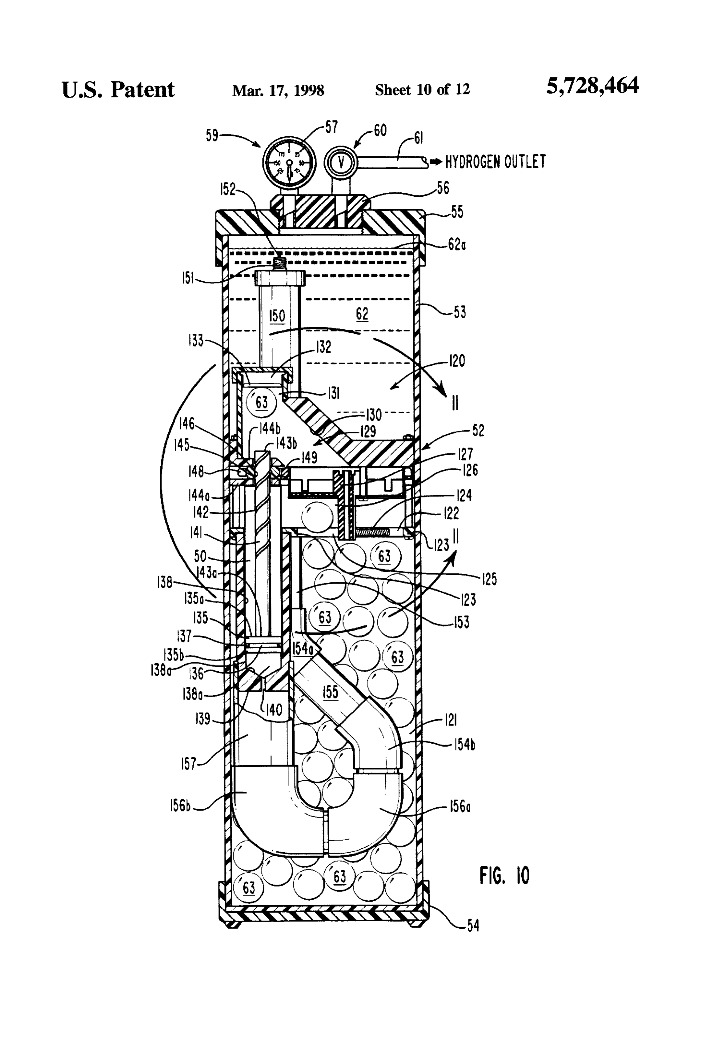
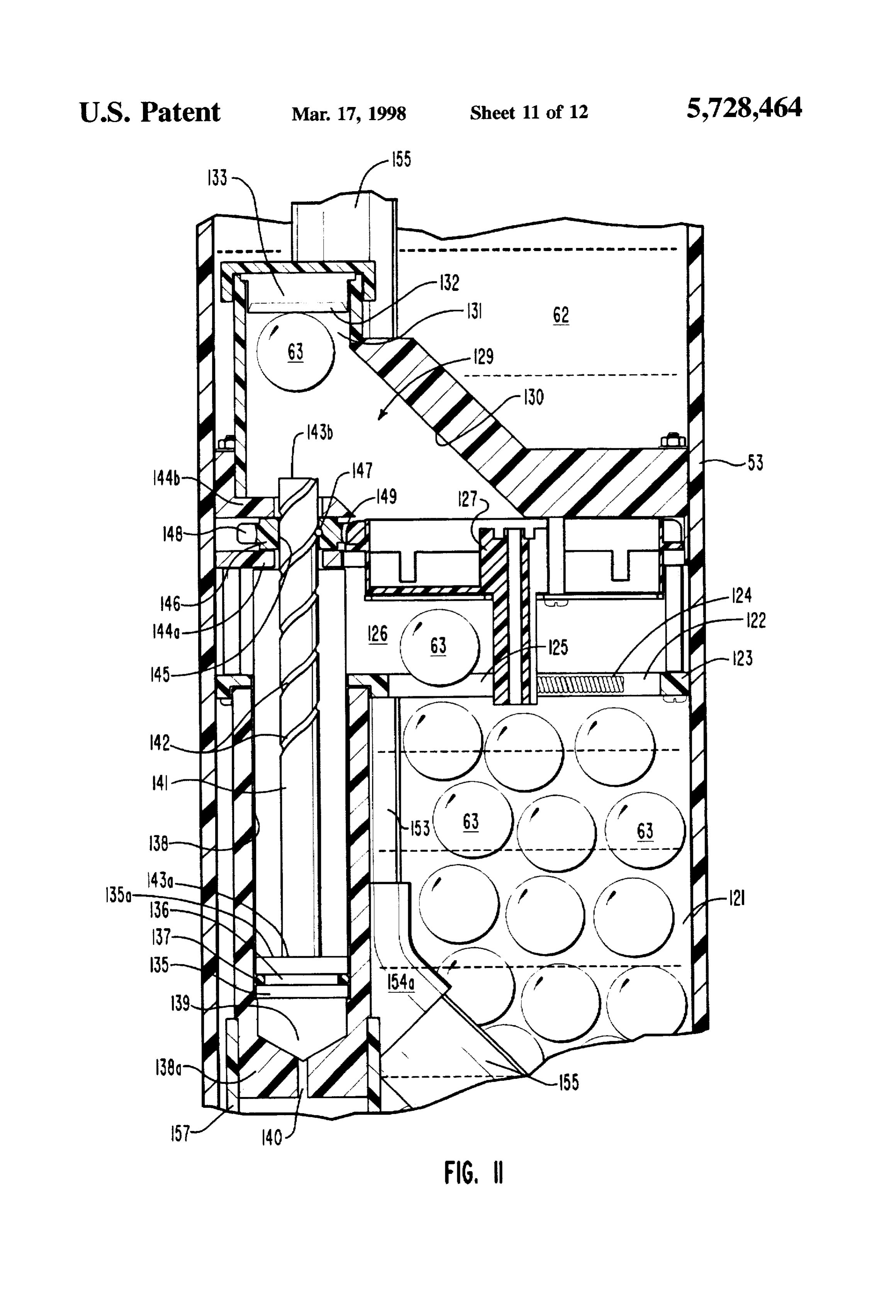
therefore be light in weight and accordingly can be safely FIG. 10 shows a view like FIG. 7 of still another or third arranged as a portable system in, for example, a vehicle for embodiment of a hydrogen generation system of the inven providing hydrogen gas to fuel an internal combustion tion contained in a cylindrical tank or vessel; engine or fuel cell that is the power source for that vehicle. FIG. 11 shows an enlarged sectional view taken with the BRIEF DESCRIPTION OF THE DRAWINGS line 11-11 of FIG. 10; and
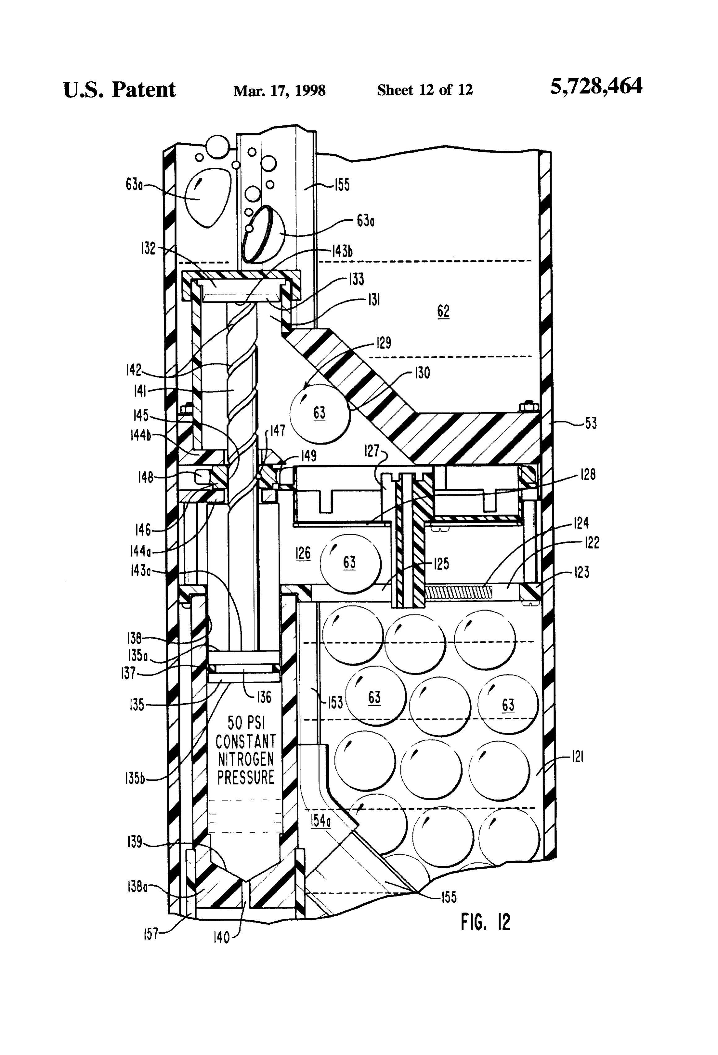
These and other objects and features of the invention in FIG. 12 shows the view of FIG. 11 with a pellet shown as hydrogen generation systems and fuel pellets therefore will having been split and reacting with water as shown in FIG. become more fully apparent from the following description 25 9.
in which the inventions are described in detail in conjunction DETALED DESCRIPTION with the accompanying drawings.
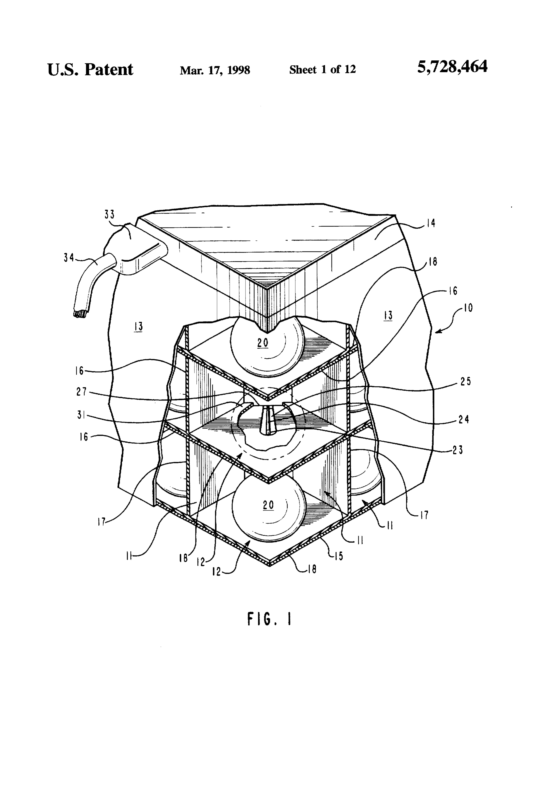
FIG. 1 shows a sectional view of a portion of a bank of The advantages to the use of hydrogen as a fuel source cells of a first embodiment of a hydrogen generation system 30 have long been recognized as have the problems associated of the invention, showing an embodiment of coated spheri with such use.
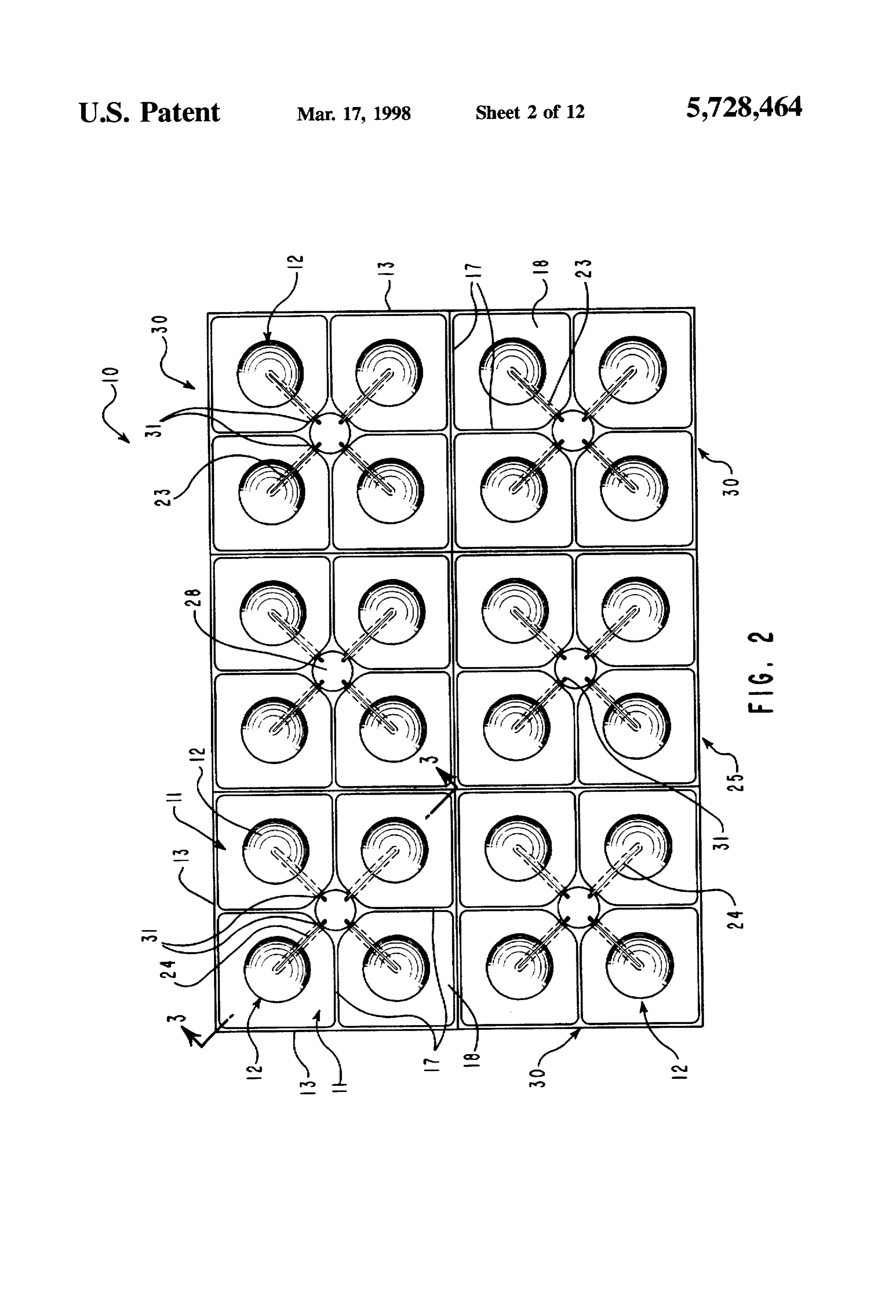
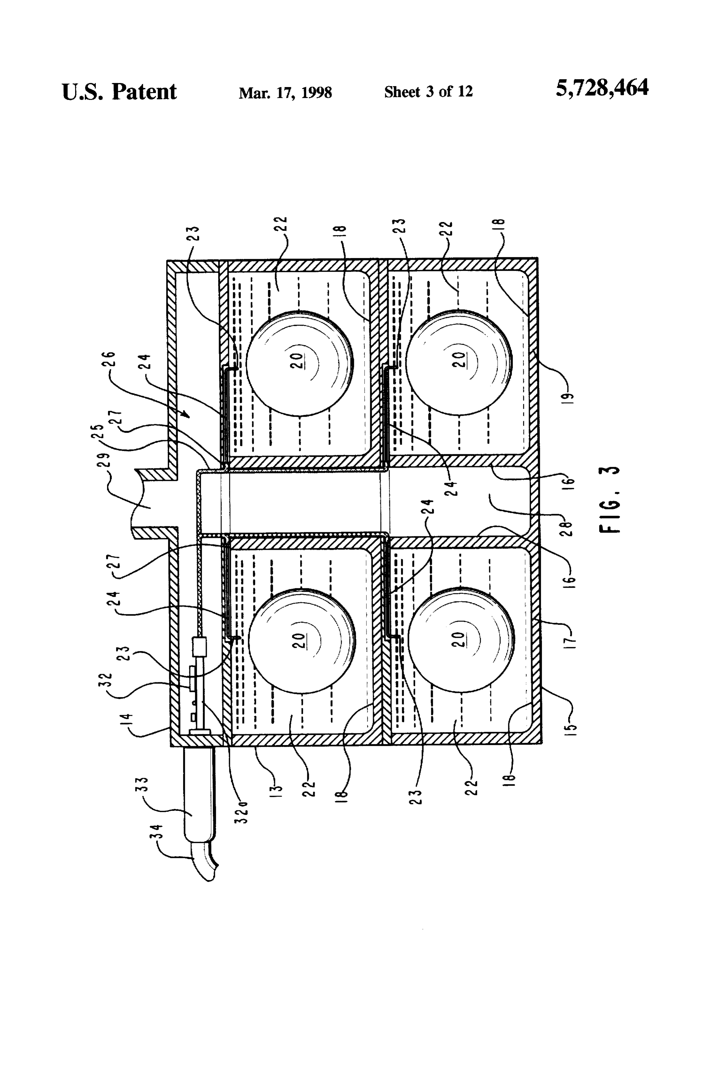
cal pellets of the invention maintained in top and bottom Nitrogen generated as a by-product from chlor-alkali cells of a cell stack with a sphere shown in broken lines in production or hot steam passed over colte processes, it has a center cell, with a positive electrical contact shown extend long been well known that hydrogen gas can be produced in ing into the center cell, and showing an electrical coupling 35 a chemical process utilizing an alkali metal or metal hydride plug fitted into a receptacle arranged in the side of the bank reacted with water. Such chemical production is, however, of cells; not without problems, but can produce more hydrogen per FIG. 2 shows a top plan view of the bank of cells of FIG. system volume than other systems. Also, even though the 1 with the top removed exposing a layer of cell segments, it materials that are preferred for use in this invention are not being understood that each layer contain a number of found free in nature, and large amounts of power are used in segments of four individual cells each arranged as a square, their refinement, these materials are still plentiful and com the four cells shown as venting into a common center paratively cheap and their use in a system of the invention, passage; as described below, is economically practical. FIG. 3 shows an expanded side elevation sectional view Heretofore, hydrogen generation systems have generally of a two layer stack of cells taken along the line 3-3 of FIG. 45 involved large and heavy storage tanks for storing hydrogen 2, and showing a positive electrical contact extending into gas at high pressure. Such systems, therefore, have not been each cell that connects through a circuit to a voltage source; practical for use as portable systems. The hydrogen genera FIG. 4 shows a schematic view of the hydrogen genera tion systems of the present invention all provide hydrogen tion system of FIGS. 1 through 3, showing the spherical on demand as hydrogen is produced in the invention as it is pellets opened thereacross, exposing their metal cores, used and therefore require that only a low pressure tank be showing the system passing hydrogen as it produces into a utilized for holding the produced gas. Accordingly, the storage tank, and showing a computer electronically con embodiments of the present invention provide a first prac nected to the storage tank and bank of cells for providing tical truly portable system that is suitable for producing system control; hydrogen gas, as needs, to fuel an internal combustion FIG. 5 shows an exploded profile perspective view of 55 engine, fuel cell, or the like.
another or second embodiment of a hydrogen generation As a first embodiment of the present invention in a system of the invention shown fitted into a cylindrical vessel hydrogen generation system, FIG. 1 shows a corner of a or tank, and including a straight open tube as a spherical bank of cells 10 that are groupings or segments of identical pellet loading arrangement to feed spherical pellets of the individual cells 11, with each cell shown as containing a invention into the vessel or container; coated pellet 12, of the invention. The bank 10 is preferably FIG. 6 shows an assembled profile perspective view of the formed from a conductive material, preferably steel plates, hydrogen generation system of FIG. 5. showing the tube forming an arrangement of interconnected individual plates fitted through the system and past, a spring barrier for 13 that upstanding walls and right angle corners. The passing the spherical pellets therethrough, shown in broken groupings of cells are closed by a top section 14 and bottom lines, and into the vessel or tank; 65 plate 15, respectively, forming a rectangular shape bank of FIG. 7 shows a profile longitudinal sectional view of the cells 10. Within the bank of cells 10, the individual cells 11 vessel or tank with the assembled hydrogen generation are formed between equally spaced horizontal flat dividers
Page 17
16 and intersecting equally spaced vertical flat dividers 17. through a common collecting tube 28 that, in turn, connects So arranged, the cells 11 are electronically isolated from one into a supply line 29. The supply line 29, as shown in FIG. another, and each mounts a positive contact 23 therein, with 4, is connected to pass hydrogen gas as is produced to all of the cells of the bank of cells 10 grounded. Electrically hydrogen storage tank 30.
non-conductive horizontal spacers or separators 18 are pref For restricting passage of the light salt solution 22 out erably arranged within the bank of cells 10 for separating from and insulating each cell from the cell below and above, with 28, oran individual cell 11 into the common collecting tube into another cell or cells 11, as could occur through the a corner of which separator 18 arranged to fit over the cell open upper opening 31 of the cell below functioning as a flap valve. over by corner corner 31 of 27, the upper corner opening is closed the horizontal spacer or separator 18
Accordingly, to function as flap valves, the spacers or 10 that is arranged in the cell above, which corner 31 to thereby separators 18 need to be formed of a flexible non-conductive function as a flap valve. In practice, hydrogen gas as is material, such as rubber, plastic, or the like. Which material generated is under sufficient pressure to lift the horizontal should also be non-reactive with the chemicals as are involved in the generation of hydrogen by the invention, and to spacer or separator corner 31 off the cell 11 upper corner 27. provide for venting the hydrogen into the common the products of which chemical reactions, as set out here 15 collecting inbelow. A plastic material identified as Teflon TM manufac 31 will return tube 28. After the hydrogen is vented, the corner tured by DuPont is preferred as the flexible non-conductive over the cell upper to its original attitude covering and sealing material as separators 18 of the invention. corner 27 opening, prohibiting a back flow into that cell.
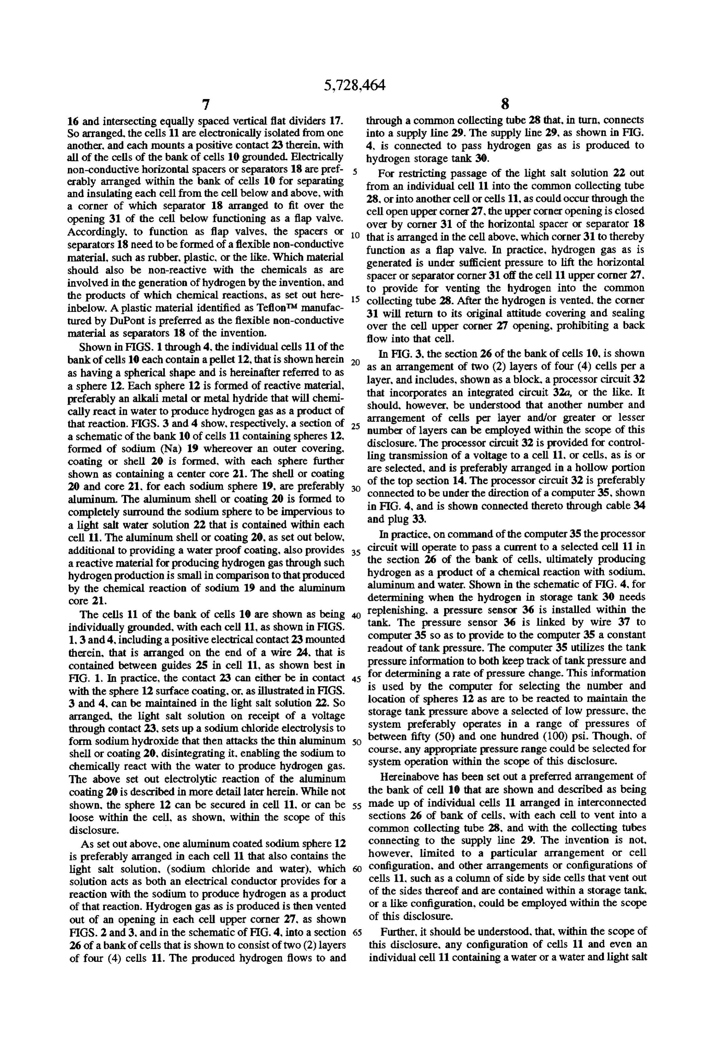
Shown in FIGS. 1 through 4, the individual cells 11 of the bank of cells 10 each contain a pellet 12, that is shown herein as InanFIG. 3, the section 26 of the bank of cells 10, is shown as having a spherical shape and is hereinafter referred to as layer, and includes, ofshown arrangement two (2) layers of four (4) cells per a as a block, a processor circuit 32 a sphere 12. Each sphere 12 is formed of reactive material, preferably an alkali metal or metal hydride that will chemi that incorporates an integrated circuit 32a, or the like. It should, however, be understood that another number and cally react in water to produce hydrogen gas as a product of arrangement of cells per layer and/or greater or lesser that reaction. FIGS. 3 and 4 show, respectively, a section of 25 number of layers can be employed within the scope of this a schematic of the bank 10 of cells 11 containing spheres 12, disclosure. The processor circuit 32 is provided for control formed of sodium (Na) 19 whereover an outer covering. ling transmission of a voltage coating or shell 20 is formed, with each sphere further are selected, and is preferably to a cell 11, or cells, as is or arranged in a hollow portion shown as containing a center core 21. The shell or coating 20 and core 21, for each sodium sphere 19, are preferably 3) of the top section 14. The processor circuit 32 is preferably connected to be under the direction of a computer 35, shown aluminum. The aluminum shell or coating 20 is formed to in completely surround the sodium sphere to be impervious to andFIG. plug 4, and is shown connected thereto through cable 34
a light salt water solution 22 that is contained within each In practice, on command of the computer 35the processor cell 11. The aluminum shell or coating 20, as set out below, additional to providing a water proof coating, also provides 35 circuit will operate to pass a current to a selected cell 11 in a reactive material for producing hydrogen gas through such the section 26 of the bank of cells, ultimately producing hydrogen production is small in comparison to that produced hydrogen as a product of a chemical reaction with sodium, by the chemical reaction of sodium 19 and the aluminum aluminum determining and water. Shown in the schematic of FIG. 4, for when the hydrogen in storage tank 30 needs core 21.
The cells 11 of the bank of cells 10 are shown as being replenishing, a pressure sensor 36 is installed within the individually grounded, with each cell 11, as shown in FIGS. tank. The pressure sensor 36 is linked by wire 37 to 1.3 and 4, including a positive electrical contact 23 mounted computer readout of 35 so as to provide to the computer 35 a constant tank pressure. The computer 35 utilizes the tank therein, that is arranged on the end of a wire 24, that is pressure information contained between guides 25 in cell 11, as shown best in for determining a ratetoofboth keep track of tank pressure and pressure change. This information
FIG. 1. In practice, the contact 23 can either be in contact 45 with the sphere 12 surface coating, or, as illustrated in FIGS. is used by the computer for selecting the number and 3 and 4. can be maintained in the light salt solution 22. So location of spheres 12 as are to be reacted to maintain the storage tank pressure above a selected of low pressure, the arranged, the light salt solution on receipt of a voltage system preferably operates in a range of pressures of through contact 23, sets up a sodium chloride electrolysis to form sodium hydroxide that then attacks the thin aluminum 50 between fifty (50) and one hundred (100) psi. Though, of shell or coating 20, disintegrating it. enabling the sodium to course, any appropriate pressure range could be selected for chemically react with the water to produce hydrogen gas. system operation within the scope of this disclosure. The above set out electrolytic reaction of the aluminum Hereinabove has been set out a preferred arrangement of coating 20 is described in more detail later herein. While not the bank of cell 10 that are shown and described as being shown, the sphere 12 can be secured in cell 11, or can be 55 made up of individual cells 11 arranged in interconnected loose within the cell, as shown, within the scope of this sections 26 of bank of cells, with each cell to vent into a disclosure. common collecting tube 28, and with the collecting tubes As set out above, one aluminum coated sodium sphere 12 connecting to the supply line 29. The invention is not, is preferably arranged in each cell 11 that also contains the however, limited to a particular arrangement or cell light salt solution, (sodium chloride and water), which configuration, and other arrangements or configurations of solution acts as both an electrical conductor provides for a cells 11, such as a column of side by side cells that vent out reaction with the sodium to produce hydrogen as a product of the sides thereof and are contained within a storage tank, of that reaction. Hydrogen gas as is produced is then vented or a like configuration, could be employed within the scope out of an opening in each cell upper corner 27, as shown of this disclosure.
FIGS. 2 and 3, and in the schematic of FIG.4, into a section 65 Further, it should be understood, that, within the scope of 26 of a bank of cells that is shown to consist of two (2) layers this disclosure, any configuration of cells 11 and even an of four (4) cells 11. The produced hydrogen flows to and individual cell 11 containing a water or a water and light salt
Page 18
solution and maintaining a single or more non-reactive housing 52, as shown best in FIG.7, is an open tube 53 with material coated spherical pellets of a reactive material, such a bottom cover 54 secured across a lower or bottom end as an alkali metal, metal hydride, or the like, as is used to thereof, and a top cover 55 arranged for closing over the produce hydrogen gas, will come within the scope of this cylinder top end, in sealing engagement therewith and may be removable for fitting the hydrogen generator 51 therein.
disclosure. For example, for the invention, a single cell 11 5 The alone could be arranged as the hydrogen generation system top cover 55, as shown, includes a center hole that is of the invention, wherein is contained a measured volume of threaded at 56 to accommodate a threaded plug 57 turned a light salt solution 22, with the cell containing a pellet 12 therein. The plug, as shown includes ports 58a and 58b that and is connected to receive a voltage passed into the light are each threaded to each receive a threaded stem of, salt solution, forming sodium hydroxide. With the sodium 10 60. The valvea 60, respectively, conventional pressure gauge 59 and a valve as shown, connects to a line 61 that is a hydroxide, in turn, reacting with so as to break down the hydrogen outlet line. So arranged, the pressure of hydrogen coating 20 of pellet 12, to expose the reactive material 19 to gas within the cylindrical housing 52 can be read out by the water in solution 22. In that reaction, hydrogen is observing needle positioning over a scale of the pressure generated as a product. The residue of such chemical reac gauge 59 and, as needed, the valve 60 can be operated to tion as remains in cell 11 can then be removed, and a new 15 pass hydrogen from the cylindrical housing and into the line light salt solution 22 and pellet 12 introduced therein and the 61. The line 61, in turn, can connect to provide hydrogen as process repeated. a fuel to an internal combustion engine, fuel cell, or the like, In practice, the preferred pellet 12 for the first embodi as desired, within the scope of this disclosure. ment of a hydrogen generation system of the bank of cells 20 Shown in FIGS.5 and 7through9, the cylindrical housing 10, as set out above, is formed as a sphere of sodium material 52 contains a volume of water 62 therein to cover the 19 that has received an aluminum coating 20 applied over its hydrogen generator 51 fitted therein, and includes a number outer surface, and preferably includes a center core 21, that of spherical pellets 63 that are contained beneath a base plate is preferably also formed of aluminum. The pellet 12 is 81 of the hydrogen generator that will float in water to both shown arranged in cell 11 that also contains a light salt rise in a feed tube 91 of the hydrogen generator and, when (NaCl) solution that, to generate hydrogen, receives a volt 25 discharged therefrom, will rise through the water to the age passed therein setting up an electrolysis. The electrolysis surface, as illustrated in FIG. 9 and as described above, the forms sodium hydroxide that attacks and dissolves, in a pellet core material will react with the water, illustrated by matter of seconds, the thin protective aluminum shell, layer bubbles 64, producing free hydrogen gas and with sodium or coating 20. The sodium material 19 is thereby exposed to hydroxide remaining in solution in the water 62, set out in the water in solution 22 and a chemical reaction therebe 30 the formula below:
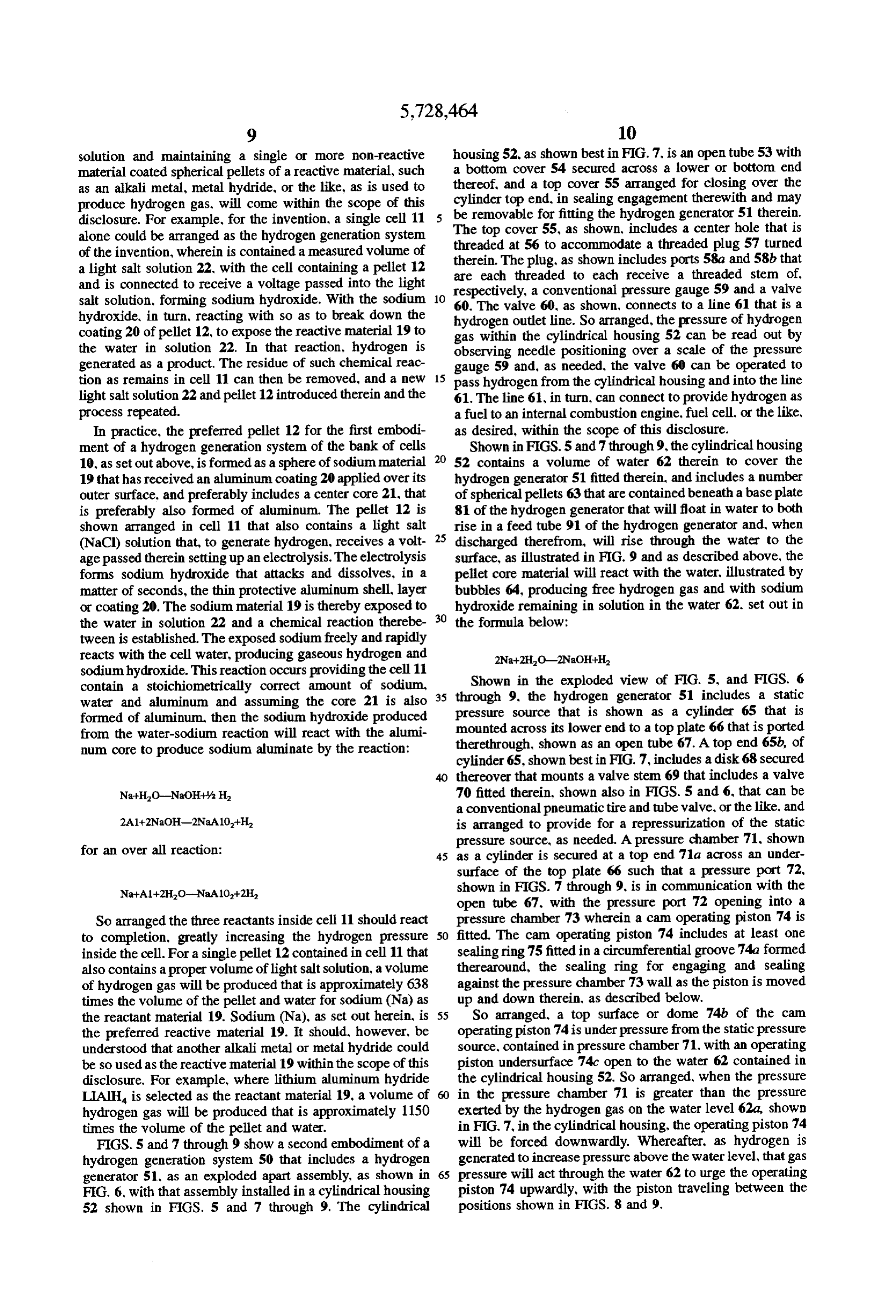
tween is established. The exposed sodium freely and rapidly reacts with the cell water, producing gaseous hydrogen and sodium hydroxide. This reaction occurs providing the cell 11 Shown in the exploded view of FIG. 5, and FIGS. 6 contain a stoichiometrically correct amount of sodium, 35 through water and aluminum and assuming the core 21 is also pressure 9,source the hydrogen generator 51 includes a static that is shown as a cylinder 65 that is formed of aluminum, then the sodium hydroxide produced from the water-sodium reaction will react with the alumi mounted across its lower end to a top plate 66 that is ported num core to produce sodium aluminate by the reaction: therethrough, shown as an open tube 67. A top end 65b, of cylinder 65, shown best in FIG. 7, includes a disk 68 secured thereover that mounts a valve stem 69 that includes a valve 70 fitted therein, shown also in FIGS. 5 and 6, that can be a conventional pneumatic tire and tube valve, or the like, and is arranged to provide for a repressurization of the static for an over all reaction:
pressure source, as needed. A pressure chamber 71, shown 45 as a cylinder is secured at a top end 71a across an under surface of the top plate 66 such that a pressure port 72.
shown in FIGS. 7 through 9, is in communication with the open tube 67, with the pressure port 72 opening into a
So arranged the three reactants inside cell 11 should react pressure chamber 73 wherein a cam operating piston 74 is to completion, greatly increasing the hydrogen pressure 50 fitted. The cam operating piston 74 includes at least one inside the cell. For a single pellet 12 contained in cell 11 that sealing ring 75 fitted in a circumferential groove 74a formed also contains a proper volume of light salt solution, a volume therearound, the sealing ring for engaging and sealing of hydrogen gas will be produced that is approximately 638 against the pressure chamber 73 wall as the piston is moved times the volume of the pellet and water for sodium (Na) as up and down therein, as described below. the reactant material 19. Sodium (Na), as set out herein, is 55 So arranged, a top surface or dome 74b of the cam the preferred reactive material 19. It should, however, be operating piston 74 is under pressure from the static pressure understood that another alkali metal or metal hydride could source, contained in pressure chamber 71, with an operating be so used as the reactive material 19 within the scope of this piston undersurface 74c open to the water 62 contained in disclosure. For example, where lithium aluminum hydride the cylindrical housing 52. So arranged, when the pressure LIAH is selected as the reactant material 19, a volume of in the pressure chamber 71 is greater than the pressure hydrogen gas will be produced that is approximately 1150 exerted by the hydrogen gas on the water level 62a, shown times the volume of the pellet and water. in FIG. 7, in the cylindrical housing, the operating piston 74 FIGS. 5 and 7 through 9 show a second embodiment of a will be forced downwardly. Whereafter, as hydrogen is hydrogen generation system 50 that includes a hydrogen generated to increase pressure above the water level, that gas generator 51, as an exploded apart assembly, as shown in 65 pressure will act through the water 62 to urge the operating FIG. 6, with that assembly installed in a cylindrical housing piston 74 upwardly, with the piston traveling between the 52 shown in FIGS. 5 and 7 through 9. The cylindrical positions shown in FIGS. 8 and 9.
Page 19
A cam rod 76 is shown in FIGS. 5 and 7 through 9. hydrogen outlet 61, and the gas pressure is below that of the secured to extend axially, at a right angle, from the center of static pressure in cylinder 65, that static pressure acts on the the undersurface of the operating piston undersurface 74c. pistons 74 and 92, as describe above, to move them to the The cam rod 76 includes a cam track 77, shown as a helix positions shown in FIG. 9. The travel of the reactor piston groove that is formed therearound and wherein a follower 92 to split a spherical pellet 63, as shown, to generate ball 79 of a follower gear 78 is fitted to roll. So arranged, the additional hydrogen. With the operating piston 74 travel to follower gear 78 is journaled to turn on the cam rod 76 and turn the carousel dispenser disk 85 so as to align hole 90 is maintained within a cavity 80 between an inner or lower therethrough with the bottom plate hole 81a and the open surface of a bottom plate 81 and the bottom surface 71a bottom end 91a of the feed tube 91, opening the bottom pressure chamber 71 as the follower ball 79 travels along the 10 portion of the cylindrical housing 52 to the spherical pellets cam track 77. 63 maintained therein. So arranged, the spherical pellets are Shown best in FIG. 5, a carousel dispenser disk 85 is free to float upwardly through the water filled hole 90 and provided that is fitted into a depression 83 formed in an feed tube 91, with a top spherical pellet aligning with the undersurface 82 of the bottom plate 81. The carousel dis reactor piston 92. Thereafter, as hydrogen is generated by penser disk 85 is axially mounted onto a pin 86 that extends 15 the chemical reaction of the spherical pellet core with water. from the center of depression 83 and includes a nut 87 the pressure above the water level will exceed that of the arranged to be turned onto the pin 86 to journal the carousel static pressure source, causing the respective pistons 74 and dispenser disk 85 to turn in depression 83. Teeth 89 are 92 to retract to the attitudes shown in FIGS. 7 and 8. In formed around an outer circumference of the carousel dis which piston retraction, the reactor chamber 92a is opened penser disk 85 that are to engage and mesh with the teeth 78a 20 to receive a top spherical pellet 63 in the column contained of the follower gear 78. The follow gear, as set out above. in the feed tube 91, and the carrousel dispensing disk will be is fitted to the cam rod 76 to travel therealong as the ball 79 rotated back to its position shown in FIGS. 7 and 8 by travels in the cam track 77, thereby turning the follower gear turning of the follower gear 78 as the cam rod 76 is pulled 78. Which follower gear, in turn, turns the carousel dispenser back therethrough. Turning of the carrousel dispensing disk disk85. So arranged, a hole 90 that is formed in the carousel 25 85 moves the hole 90 out of alignment with the bottom plate dispenser disk 85. that contains a spherical pellet 63, when hole 81a and feed tube 91 end 91a, and captures a spherical the cam rod 76 is moved to the attitude shown in FIG. 9, pellet 63 in that hole 90 that floats to the bottom of the aligns with hole 81a through the bottom plate 81. The hole column of pellets 63 when the top pellet floats into the 81a, in turn, aligns with and is the same diameter as a bottom reactor chamber 92a, as shown.
end 91a of a feed tube 91. With the hole 81a and tube end As set out above, the bottom portion or section of the 91a aligned, the spherical pellet 63 will float upwardly cylindrical housing 52, that contains a supply of spherical through the feed tube 91 and out from a top end 91b thereof pellets 63, is open to replenish the supply in feed tube 91 as and into a reactor chamber 92a, as shown in FIG. 8. So hydrogen flows out through the hydrogen outlet line 61. A arranged, an individual spherical pellet 63 is positioned, as demand system is thereby provided that will continue to shown best in FIG. 8, between a face 93 of a reactor piston 35 operate, maintaining hydrogen gas under low pressure of 92 and a sharp edge 95 of a fixed flat reactor blade 94. from approximately, a high pressure of approximately one Shown in FIG.9, the reactor piston 92 has been extended hundred (100) psi to below the pressure of the static pressure into reactor chamber 92a, urging the spherical pellet 63 source of approximately fifty (50) psi. Allowing therefore, therein against the sharp edge 95 of the reactor blade 94 to for a use of lightweight inexpensive materials to be used for cut the pellet in half. The two pellet halves to then float out the cylindrical housing 52 to safely contain the generated of an opening 96 formed through the top plate 66, above the hydrogen gas for use, on demand, as a fuel. reactor blade 94. The pellet halves are with bubbles 64 being After the spherical pellets 63 are used and any remaining emitted from the pellet material surface, which bubbles hydrogen vented, the threaded plug 57 can be removed and represent formation of hydrogen gas from a chemical reac the water containing sodium hydroxide and the spherical tion of the pellet core material with water, as set out above. 45 pellet 63 coverings can be removed therefrom to be replaced To provide for operation of the reactor piston92, to extend with fresh water 62. At this time, as required, the static out from a chamber 97 with the piston face 93 striking pressure source contained in cylinder 65 can be restored by contacting the spherical pellet 63, as shown in FIG. 9. an passing a gas, that is preferably an inert gas such as nitrogen, opening 98 is provided through the side of open tube 67. A under pressure, through the valve 70. To refill the cylindrical rear surface 99 of the reactor piston 92 is thereby exposed to 50 container 52 bottonportion with spherical pellets 63, an end the static pressure source contained in cylinder 65. To of a straight refilling tube 105, shown in FIGS. 5 and 6, is maintain the pressure in cylinder 65, the reactor piston 92. passed into the cylindrical container through the center hole like the operating piston 74, includes at least one groove 100 56 and fitted through hole 106 through the top plate 66. formed therearound wherein a sealing ring 101 is positioned. through hole 107 formed through bottom plate 81 and Though, of course, additional grooves and sealing rings can 55 through a hole 108 formed through a bottom cover 104. be included to provide additional sealing, as desired. Which bottom cover includes a wide opening 103 wherein In operation, to provide the travel of the operating piston the carousel dispensing disk 85 is fitted, with bolts 102, 74 and guillotine piston 92, as described above. both piston shown in the exploded view of FIG. 5, for turning through faces 74b and 99, respectively, are open to the static pressure bottom cover holes 109b and 109c and into tapped holes source contained in cylinder 65. Provided the hydrogen gas formed in the undersurface of the bottom plate 81. pressure in the cylindrical housing 52 above a surface 62a of For restricting spherical pellets 63 from reentering and water 62 is greater than the pressure of the static pressure floating upwardly through the hole 108 and into the area source. The hydrogen gas pressure acting through water 62 above the bottom plate 81 to be lost as fuel sources, the hole on the operating piston face 74c and reactor piston face 93 108 preferably includes a flexible coil spring 110, or like maintains the pistons 74 and 92, respectively, in the posi 65 barrier, that is connected at its ends in holes 109a and 109b tions shown in FIGS. 7 and 8. When, however, hydrogen gas to bottom plate 81 to extend across the hole 108. In practice, has been vented from the cylindrical housing 52, as through the spring 110, upon being contacted by the refilling tube
Page 20
105 end 105a, is pushed aside by that end of the refilling circumference of the carousel dispenser disk 127. So tube, stretching the spring to the attitude shown in FIG. 6. arranged, as rod 141 travels up and down through hole 145 Whereafter, spherical pellets 63 are passed through the of the follower gear 146, causing the follower gear teeth 148 refilling tube 105, filling the area below the bottom plate 81 to turn the teeth 149 of the carousel dispenser disk 127. as and bottom cover 103, as shown best in FIG. 7. set out above, the carousel dispenser disk turning to pass at Another or third embodiment of the present invention in least one spherical pellet 63 into the reactor passage 129. a hydrogen generation system 120 is shown in FIGS. 10 Upward travel of the rod 141 moves a top end 143b thereof through 12, that is for installation in cylindrical housing 52. between the attitude shown in FIGS. 10 and 11 to the attitude Though, it should be understood, another vessel arrange shown in FIG. 12. In FIG. 12 the rod 141 top end 143b is ment could be so used within the scope of this disclosure. 10 shown engaging the sharp edge 133 or reactor blade 132. In The cylindrical housing 52 of this embodiment also includes which rod 141 travel, with a spherical pellet 63 positioned an open tube 53 with bottom and top covers 54 and 55, in the reactor chamber 131, the rod top end 143b will engage respectively, with the top cover 55 shown as including the and force the spherical pellet 63 into the reactor blade 132 threaded a hole 56 wherein a threaded plug 57 is turned. Like sharp edge 133, splitting the pellet in two, shown as pellet the embodiment 51, the threaded plug 57, of this embodi 15 halves 63a. The core material of the pellet 63 halves 63a ment includes the pressure gauge 59 and valve 60 that reacts with the water 62, giving off hydrogen gas, shown as connects to pass hydrogen gas into a hydrogen outlet line 61. bubbles, as the product of the reaction. Which bubbles float Like the second embodiment, the cylindrical housing 52 to the water surface 62a, pressurizing the area of the vessel of the hydrogen generation system 120 preferably includes thereabove.
a bottom section or portion 121 that contains spherical 20 The hydrogen generation system 120 of this embodiment, pellets 63, like those described above, that are passed therein like the hydrogen generation system 51 set out above, is through a refilling tube, not shown, which filling tube is like operated when the hydrogen gas pressure above the level the refilling tube 105 and is passed through a hole 122, 62a of water 62 falls below the pressure of a static pressure formed through a bottom divider 123, and stretches aside a source, shown in FIG. 10 as a cylinder 150 to generate spring 124. Filling of the cylindrical housing bottom portion 25 hydrogen gas by splitting a spherical pellet 63 in half, shown 121 with spherical pellets 63 is accomplished with the plug as halves 63a in FIG. 12. The cylinder 150 is identified as 57 removed whereafter the spherical pellets 63 are poured containing nitrogen gas at a pressure of fifty (50) PSL. To fill through the refilling tube. the cylinder 150, a threaded stem 151 is shown in FIG. 10 The bottom divider 123 includes an inlet hole 125 where extending out of a top end thereof that includes a valve 152 through a spherical pellet 63 is shown as having floated 30 that may be a bicycle tube valve, or the like, for use in filling upwardly into an inlet chamber 126 located below a carousel or refilling the cylinder when the vessel 52 plug 57 is dispenser disk 127. The carousel dispenser disk 127 is also removed.
for restricting passage of a spherical pellet 63 therethrough In the system 120 embodiment, the static pressure source and is essentially like the carousel dispenser disk 85 as was is open to pressurize a bottom face 135b of the reactor piston described above and shown in FIGS. 10 and 11 and will not 35 135 so as to move that piston to the attitude shown in FIG. be further described herein. FIG. 12 shows the carousel 12 when the hydrogen gas pressure exerted on the piston top dispenser disk 127 as having turned to align a hole or face 135a is less than that of the static pressure source that opening 128 therethrough that a pellet 63 has floated is contained in cylinder 150. To provide for which opening, through, and into a reactor passage 129. For channeling each the reactor piston sleeve 138 is closed at a bottom end 138a special pellet to a reactor chamber 131, the reactor passage forming an open area 139, with the bottom end 138a 129 includes an inwardly sloping upper wall 130 that the including an opening 140 formed therethrough. The sleeve spherical pellet 63 will strike and slide upwardly along to be bottom end receives an end of a pipe 157 secured thereover. directed into reactor chamber 131. The reactor chamber 131 The pipe 157 is one end of a series of connected pipes that includes a reactor blade 132 fitted thereacross, that has a couple together to connect to and extend from a bottom end sharp edge 133 to engage spherical pellet 63. 45 of the cylinder 150 to transfer pressure therethrough. The The hydrogen generator system 120, as shown in FIGS. pipes, as shown in FIGS. 10 and 11, to include a first straight 10 through 12, preferably includes a single reactor piston pipe 153 that extends from the cylinder 150 end and con 135 that has at least one groove 136 formed therearound nects to an angle fitting 154a that, in turn, as shown best in wherein is maintained a sealing ring 137. The reactor piston FIG. 10, connects to a straightpipe 155that, in turn connects is maintained to travel up and down in a sleeve 138 that is to another angle fitting 154b. The angle fitting 154b, in turn, open to the inlet chamber 126 and contains the vessel water connect to a pair of ninety (90) degree elbows 156a and 62. Accordingly, an upper surface 135a of reactor piston is 156b that, in turn, connect to a bottom end of the pipe 157. under pressure from a gas pressure that is exerted on the top The pipes 153 through 157 are preferably plastic for pro 62a of water 62, as shown in FIG. 10. viding a convenient easily assembled plumbing arrangement Shown in FIGS. 10 through 12. a rod 141 that includes a 55 for connecting the static pressure source contained in cyl helix track 142 formed therealong, is axially secured at its inder 150 to the sleeve 138 bottom end below the reactor end 143a to the reactor piston upper surface 135a, An upper piston 135.
rod end portion is fitted to slide through aligned holes In practice, the cylinder 150 static pressure is initially formed through spaced apart parallel plates 144a and 144b overcome by pressurizing the vessel above the water level and through a hub opening 145 in a follower gear 146. The 62a as by introducing a back pressure through the hydrogen follower gear 146 is like and, it should be understood, outlet line 61, preferably utilizing an inert gas such as functions like the follower gear 78 and, like follower gear nitrogen. The reactor piston 135 will thereby be moved and 78, includes a ball 147 maintained in a hole formed as a seat the carousel dispenser disk 127 turned to the attitudes shown in the wall of hub opening 145 that is fitted to travel along in FIGS. 10 and 11. Whereafter, as the system is vented out the helix track 142. The follower gear 146 includes teeth 148 65 through the hydrogen outlet line 61, the pressure in cylinder formed around its outer circumference that are in meshing 150 will come to exceed that gas pressure above the water engagement with teeth 149 that are formed around the outer level 62a. Thereat, the reactor piston 135 will be moved to
Page 21
the attitude shown in FIG. 12, splitting a spherical pellet 63 they are cheaper and are accordingly preferred. The alumi to open its core material to water 62 and react therewith to num thin shell or coating can be formed by a conventional form hydrogen to pressurize the vessel above the water manufacture, receiving sodium poured therein. It is, level, resetting the system to the attitude shown in FIGS. 10 however, preferred to coat the sodium sphere, that already and 11. Accordingly, as hydrogen gas is discharged through contains a solid aluminum core, with a thin coating of the hydrogen outlet 61, the system will operate to renew the approximately one ten thousandth (0.001) of an inch by hydrogen gas pressure in the vessel 52 until all the spherical plating the aluminum thereon, as in an organic electrolyte, or pellets 63 have all been split and reacted. Whereafter, the by plating with aluminum in a vacuum. In such plating, the system must be recharged. aluminum may be vaporized utilizing a tungsten wire, with While not shown, it should be understood that the above the sodium spheres rotated in the "line of sight" to the vapor set out embodiments of the hydrogen generation systems of stream, to receive the aluminum coating, or other appropri the invention can be used to augment and/or replenish other ate process can be used. The present invention, it should be hydrogen sources, including highly pressurized sources as understood, is not limited to a particular process of manu have been produced by electrolysis, by a solar array, or the facture of the coating on the reactive material spheres or any like, within the scope of this disclosure. 15 specific thickness of aluminum coating. The hydrogen generation systems of the invention, as The described pellet 63 for use for generating hydrogen discussed above, lend themselves to use as a truly portable gas in the second and third embodiments of hydrogen systems suitable for replenishing, on demand, a low pressure generation systems 51 and 120 of the invention is also storage tank with hydrogen to maintain tank pressure within coated to be water impervious, but for that coating utilizes a low pressure range of, for example, from 50 to 100 psi. a plastic or plastic like material, such as, but not limited to, Such storage tank can therefore beformed of thin gauge thin a high density polyethylene plastic, that can be sprayed, steel sheet material, or the like, that is light in weight and dipped, or otherwise coated over the pellet surface that is would therefore be suitable for use as a fuel system for an preferably spherical but may be any convenient shape, internal combustion engine, portable fuel cell, or the like. within the scope of this disclosure. With, for such use, the systems of the invention can be 25 Preferred embodiments of my invention in systems for arranged to be easily removable and replaceable. generating hydrogen on demand, the pellets of a reactive Pellets 12 are herein shown as set out above, are prefer material, such as sodium, for reacting to form sodium, and ably consisting of a section of sodium (Na) 19 that is their use have been shown and described herein. It should, preferably spherical but may be any appropriate shape, and however be apparent that this disclosure is made by way of is coated with a thin aluminum shell or coating 20 and 30 example only and that variations and modification to the preferably but not necessarily includes an aluminum center described apparatus and pellets their use are possible within core 21, for use as a fuel for generating hydrogen gas in bank the scope of this disclosure without departing from the of cells 10. With, in the second and third embodiments of the subject matter coming within the scope of the following hydrogen generation systems 51 and 120, as set out above, claims and a reasonable equivalency thereof, which claims the spherical pellets 63 are likewise formed of sodium (Na) 35 I regard as my invention.
but are coated with a water impervious material such as high I claim:
density polyethylene, or the like, as by dipping, spraying, or 1. A pellet for use in a hydrogen generation system other appropriate process, whereby the pellet outer surface comprising, an alkali metal core selected from the group is completely covered. The preferred coating or covering is consisting of sodium and calcium or metal hydride core non brittle and resists cracking or tearing and provides a selected from the group consisting of NaH, Cah, NaAlH. water proof coating thereover, Such coating, while it must and LiAlH4; and a coating of water impervious material completely cover the pellet material, should be thin enough applied over the entire surface of said core, rendering the to be easily cut by forcing the pellet into a blade, or the like, core impervious to water.
as set out and described above. In practice, a coating 2. A pellet as recited in claim 1, wherein the pellet has a thickness of as little as 0.020 of an inch has been used 45 spherical shape.
successfully. 3. A pellet as recited in claim 1, wherein the coating is an Sodium is preferred for use as the reactive material in aluminum.
spherical pellets 63 and sodium and aluminum as is prefer 4. A pellet as recited in claim 3, wherein the pellet has an ably incorporated in the pellets 12, are, or course, abundant aluminum center that is covered by the alkali metal or metal and readily available commercially in large quantities. 50 hydride.
Sodium represents approximately 2.6% of the earth's crust. 5. A pellet as recited in claim 1, wherein the coating is and aluminum compounds make up more than 15% Neither formed from a plastic material.
metal is ever found free in nature, however, and both require 6. A pellet as recited in claim 5, wherein the plastic energy to produce. As compared to other suitable materials material is a high density polyethylene plastic. such as lithium aluminum hydride coated with aluminum, 55 that, as was set out hereinabove, is another suitable material,
Provenance
- Collection
- Cited prior art
- Original PDF
- patentimages.storage.googleapis.com →
- Filed
- 1996-01-02
- Pages
- 21
- Method
- pdftotext (the PDF's own text layer) + pdftoppm 300dpi page scans
- Source
- Google Patents bibliographic record
- Granted
- 1998-03-17
- Inventors
- Jed H. Checketts
- Transcribed from
- patentimages.storage.googleapis.com →