patent · US5830426
Aqueous hydrogen generation process
3 November 1998
Page 1 — bibliographic record
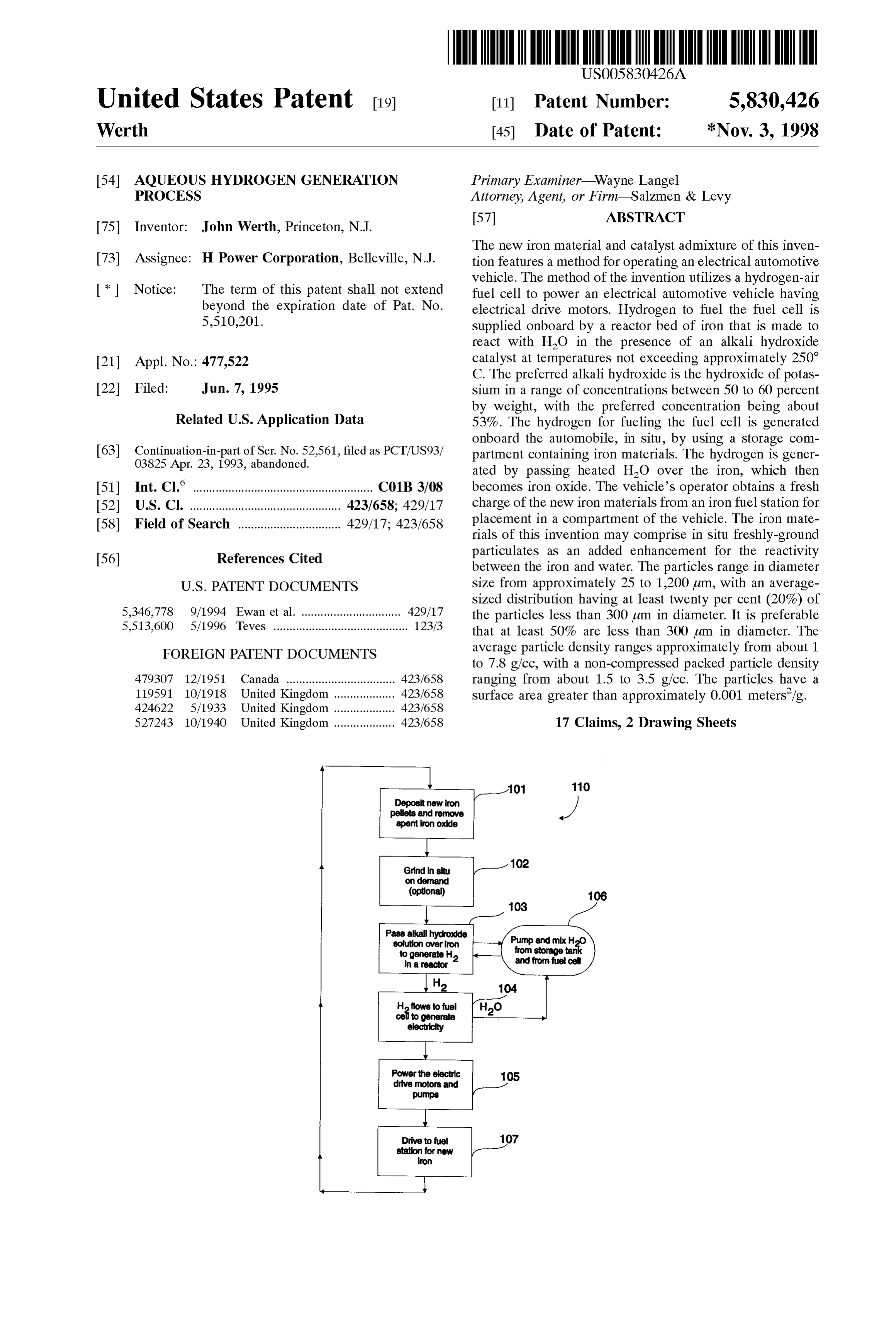
United States Patent (19) 11 Patent Number: 5,830,426 Werth (45) Date of Patent: *Nov. 3, 1998 54 AQUEOUS HYDROGEN GENERATION Primary Examiner Wayne Langel PROCESS Attorney, Agent, or Firm-Salzmen & Levy 75 Inventor: John Werth, Princeton, N.J. 57 ABSTRACT The new iron material and catalyst admixture of this inven 73 Assignee: H Power Corporation, Belleville, N.J. tion features a method for operating an electrical automotive c: vehicle. The method of the invention utilizes a hydrogen-air (*) Notice: The term of this patent shall not extend fuel cell to power an electrical automotive vehicle having beyond the expiration date of Pat. No. electrical drive motors. Hydrogen to fuel the fuel cell is 5,510,201. Supplied onboard by a reactor bed of iron that is made to react with HO in the presence of an alkali hydroxide 21 Appl. No.: 477,522 catalyst at temperatures not exceeding approximately 250 C. The preferred alkali hydroxide is the hydroxide of potas 22 Filed: Jun. 7, 1995 sium in a range of concentrations between 50 to 60 percent O O by weight, with the preferred concentration being about
Related U.S. Application Data 53%. The hydrogen for fueling the fuel cell is generated onboard the automobile, in Situ, by using a Storage com 63 Stop! of RS 2561. filed as PCT/US93/ partment containing iron materials. The hydrogen is gener 03825 Apr. 23, 1993, abandoned. ated by passing heated H2O over the iron, which then (51) Int. Cl. .................................................. C01B 3/08 becomes iron oxide. The vehicle's operator obtains a fresh 52 U.S. Cl. ............................................... 423/658; 429/17 charge of the new iron materials from an iron fuel Station for 58 Field of Search ................................ 429/17,423.65s placement in a compartment of the vehicle. The iron mate rials of this invention may comprise in Situ freshly-ground particulates as an added enhancement for the reactivity 56) References Cited between the iron and water. The particles range in diameter
sized distribution having at least twenty per cent (20%) of
CVCS . . . . . . . . . . . . . . . . . . . . . . . . . . . . . . . . . . . . . . . . . .
the particles less than 300 um in diameter. It is preferable that at least 50% are less than 300 um in diameter. The
FOREIGN PATENT DOCUMENTS average particle density ranges approximately from about 1 to 7.8 g/cc, with a non-compressed packed particle density 4793O7 12/1951 Canada ............ ... 423/658 ranging from about 1.5 to 3.5 g/cc. The particles have a 119591 10/1918 United Kingdom. ... 423/658 Surface area greater than approximately 0.001 meters/g. 424622 5/1933 United Kingdom .... ... 423/658 527243 10/1940 United Kingdom ................... 423/658 17 Claims, 2 Drawing Sheets
for rew iron
Page 2
Pass alkali hydroxide Pump and mbH solution Over iron from sto
Cell
Hflows to fuel cell to generate electricity
Power the electric 105 drive motors and pumps
Page 3
Drawing sheet — no readable text.
Page 4
AQUEOUS HYDROGEN GENERATION In addition to the distinctive catalyst of this invention, it PROCESS is additionally contemplated that an added benefit may be obtained by using a more active form of iron, to wit,
RELATED PATENT APPLICATION freshly-ground particles of iron which increase the reactivity This patent application is a continuation-in-part of PCT thereof. Such active iron is able to enter into the water/iron application, PCT/US 93/03825 (which was filed Apr. 23, reaction at lower-than-normal temperatures, even without 1993); and a continuation-in-part of U.S. patent application, catalysis. In this additional embodiment, the iron particles are ground when the vehicle is initially powered and
Ser. No. 08/052,561 (which was also filed Apr. 23, 1993, throughout vehicular operation. The instantaneous grinding abandoned). Each was assigned to a common assignee. of the iron particles in Situ is useful because iron in moist air FIELD OF THE INVENTION becomes rapidly oxidized after grinding. (AS early as fifteen minutes after grinding, iron will lose its enhanced reactivity
The present invention pertains to a hydrogen-generating when exposed to moist air.) Therefore, after the initial proceSS wherein water is passed over a bed of iron material grinding, grinding should continue onboard the vehicle or, and, more particularly, to a new, catalyzed method of alternatively, by periodically injecting freshly-ground iron generating hydrogen that utilizes lower-than-normal tem 15 fuel charges from Sealed packets.
peratures when the water reacts with the iron material. The freshly-ground reactive iron is easily deposited in a BACKGROUND OF THE INVENTION compartment in the vehicle. It is easily handled as Sealed packet(s) of freshly-ground particulates, but, additionally, it
The generation of hydrogen by passing Steam at or about can be freshly ground in situ aboard the vehicle. The 700 C. over a bed of iron is well known in the art. It is generally a simple way of obtaining hydrogen, which is particles range in diameter size from approximately 25 to 1,200 um; an average-sized distribution is one in which at drawn off and dried. One of the primary potential uses of least twenty per cent (20%) of the particles are less than 300 hydrogen can be for powering land vehicles and, in lum in diameter. It is preferable that at least 50% are less than particular, electrical automobiles. 25 300 um in diameter. The average particle density ranges The electrical automobile is currently under intense devel approximately from about 1 to 7.8 g/cc, with a non opment due to the twin needs to reduce air pollution and compressed packed particle density ranging from about 1.5 conserve fuel resources. One of the major difficulties in the to 3.5 g/cc. The particles have a Surface area greater than development of the electrical automobile is Supplying the approximately 0.001 meters/g.
power for the electrical drive motorS. Such power is cur The potassium hydroxide catalyst of this invention is truly rently furnished by batteries. Present battery technology, unique. AS the hydrogen generation of iron and Steam is very however, is not capable of providing, at a practical cost, the old, one would expect that Such a temperature-reducing energy needed to run the automobile over extended dis catalyst would have been discovered a long time ago. It is tanceS.
also unusual Since many compounds and materials have
This invention shows that hydrogen can be generated in 35 been tried, without much Success.
Situ (i.e., onboard a vehicle), and then passed into a The potassium hydroxide catalyst of this invention makes hydrogen-air fuel cell to generate electricity to power elec possible low-temperature reactors operating at or about 200 trical drive motors. C. to 250 C.; hydrogen can be produced at high rates One well-known method of hydrogen generation, no thereby without requiring large amounts of iron in the longer in use, is to generate hydrogen by passing high 40 reactor. A low-temperature reaction of this type would temperature Steam over a bed of iron. This method can be normally require impractical amounts of iron in order to too expensive and impractical for automotive purposes. The generate enough hydrogen at the usual low activity. containers needed to generate and Supply the high However, this catalyst greatly enhances the rate of reaction temperature Steam can make the cost of running the vehicle between water and iron, thus reducing the amount of iron too expensive. Further, the use of high-temperature Steam 45 needed for reaction with the water. For example, when using can be dangerous. high-temperature Steam for the hydrogen generation, a The present invention is the development of a new medium-sized electrically-powered car which has its elec hydrogen-generating process utilizing either low tricity generated by a hydrogen-air fuel cell might consume temperature Steam or water. Being able to use a low about fifty pounds of iron during a one-hour trip. In order to temperature proceSS in electrical vehicles is valuable, Since 50 obtain the same amount of hydrogen from a Steam reaction it is quite practical. In the first instance, the need to expend at 250 C., more than 400 pounds of heated iron would be energy in vaporizing the water and bringing it to a high required under present State-of-the-art methods; only about temperature is eliminated. Secondly, a process that does not fifty pounds would actually react to form hydrogen. The generate Steam is inherently simpler and Safer; it also does added weight of the iron reduces mileage. The additional not require Special pressure fittings and piping. Thirdly, the 55 350 pounds of iron would then need the requisite heat to utilization of high temperatures almost always results in bring it to operating temperature. In other words, the addi reactors that are large and heavy, Since insulation is usually tional 350 pounds of iron would be nothing short of excess required to avoid heat loss; obviously, the added weight and baggage. The need to carry and heat much more iron than is Space of large reactors are extremely detrimental in produc Stoichiometrically required is completely impractical. ing a low-cost, efficient, electrical vehicle. 60 To the best of Applicant's knowledge, no catalyst has The low-temperature process of this invention is made been shown to be effective, practical and economical in possible by a unique catalyst, which greatly enhances the accelerating the iron-water reaction attemperatures less than HO and iron reaction. The catalyst of this invention com 400 C. Catalysts that have been tried without success prises an alkaline hydroxide and, more particularly, the include Sodium chloride, Sodium Sulfate, Zinc Sulfate, Zinc preferred hydroxide of potassium, which is a true catalyst 65 chloride, potassium Sulfate, potassium chloride, lithium that is not consumed in the reaction. This catalyst is effective bromide, calcium chloride, potassium Stannate, ferrous and with ordinary commercial Sponge iron powder. ferric Sulfate, ferrous chloride and ferric chloride.
Page 5
The preferred concentration of the potassium hydroxide considered in conjunction with the Subsequent detailed catalyst of this invention is approximately 53 grams of description, in which:
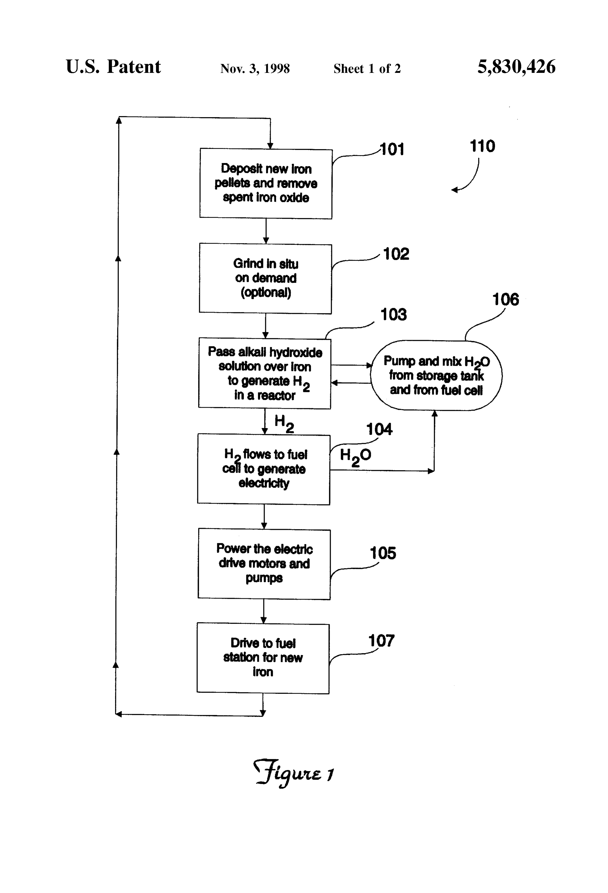
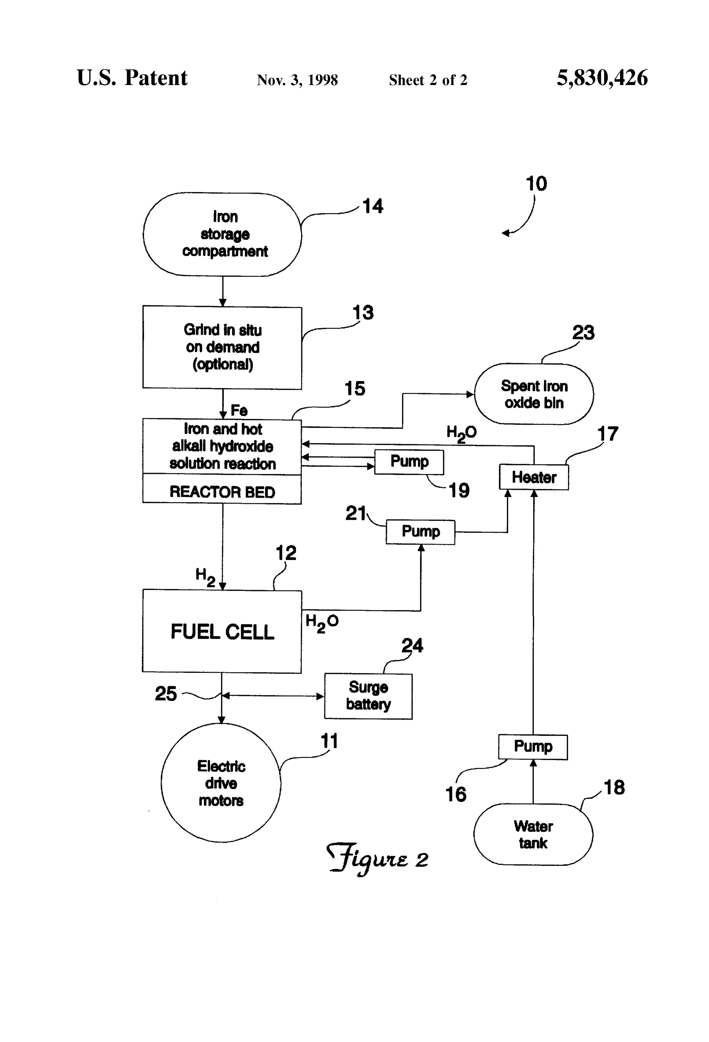
potassium hydroxide per 100 grams of Solution. FIG. 1 illustrates a flowchart diagram of a method using At this concentration, operating at 230 C., a given the inventive catalyst of this invention; and quantity of iron reacts with water at a per-minute conversion FIG. 2 depicts a Schematic diagram of the System of an rate of 3.6 percent per minute conversion of iron to iron electrical vehicle that utilizes the new catalyst of the inven oxide. This rapid conversion rate makes practical the use of tion.
iron to fuel electrical automobiles and other electrically powered land vehicles. DESCRIPTION OF THE PREFERRED It should be understood that while the other alkali hydrox EMBODIMENT ides are effective catalysts, the use of the hydroxide of potassium is preferred. The hydroxides of cesium, rubidium Generally Speaking, the invention features a method of and lithium are too expensive. The hydroxides of sodium powering an electrical vehicle by using a hydrogen-air fuel and lithium form excessively stable ferrates with the iron, cell to generate the electricity needed to power the electrical which is undesirable, because stable ferrates are difficult to 15 drive motors. Hydrogen to Supply the fuel cell is produced decompose. They also reduce the amount of catalyst in in situ, aboard the vehicle by passing low-temperature solution. The formation of the excessively stable ferrates, heated water over an iron bed contained in a reactor. The therefore, poses problems in the replenishment of the iron is bulk-loaded into the reactor; it may comprise freshly catalyst, with attendant inconvenience and the additional ground particles of iron. The iron is caused to react with the costs of labor and materials. water in the presence of an alkali hydroxide catalyst, which SUMMARY OF THE INVENTION allows the reaction to proceed at temperatures below about In accordance with the new catalyst of this invention, 250° C.
there is also provided a method for operating an electrical Now referring to FIG. 1, a flowchart diagram 110 of the automotive vehicle. The method of the invention comprises inventive method is shown. The operator of an electrical using a hydrogen-air fuel cell to power an electrical auto 25 vehicle having electrical drive motors for driving the motive vehicle having electrical drive motors. automobile, not shown, obtains a fresh charge of iron from Hydrogen to fuel the fuel cell is supplied onboard by a bed a fuel station, step 101. The spent iron (iron oxide) that is in of iron that is made to react with water in the presence of an the iron compartment is removed and replaced with the fresh alkali hydroxide catalyst at temperatures not exceeding charge of iron particles or pellets. The iron may be further approximately 250 C. The preferred alkali hydroxide is the enhanced in its reactivity with water by the continuous hydroxide of potassium in a range of concentrations between grinding of the iron particles in situ, Step 102. (This is an 50 to 60 percent by weight, with the preferred concentration optional Step, Since the catalytic reaction of this invention being about 53%. The hydrogen for fueling the fuel cell is will proceed at desirable conversion rates, and at desirable generated onboard the automobile, in situ, by using a reactor temperatures, without the need to freshly grind the iron.) The compartment containing the iron materials. The hydrogen is 35 reactor containing the iron can also be tumbled, So as to mix generated by passing water over the iron, which then or stir the iron. The grinding of the iron within the com becomes iron oxide. The vehicle's operator obtains a fresh partment can be optionally used to make the iron more charge of the iron materials from an iron fuel Station for reactive, So that the conversion of the iron to iron oxide, placement in a storage compartment of the vehicle which which is measured in percent per minute (%/min.), can take feeds the reactor compartment. The exchange of the iron 40 place at ever lower-than-normal water temperatures and at oxide with a fresh iron charge at the fuel Station can function Still better-than-normal conversion rates, as illustrated below in a manner that is similar to that of the current process for in Table 1, without the catalyst being present. returning empty Soda cans to a Supermarket. For the Spent iron (iron oxide), the fuel Station would give the vehicle 45 TABLE 1. operator a cash allowance toward the purchase of a new iron No Catalyst charge. The old, spent iron would then be recycled into fresh iron by a reduction process at the fuel Station or at a central HO Temp. (C.) Conv. Rate (Ground) Conv. Rate(Unground) distribution facility. The major difference between the Super 400 11.5 3.7 market recycling eXchange Scheme and the exchange System 3OO 4.0 18 of this invention is that the exchange of iron materials is 50 2OO 2.4 O.8 accomplished by the use of automated machinery, as is done at gasoline pumping Stations.
The iron materials of this invention may comprise in Situ The vehicle is equipped with a hydrogen-air fuel cell that freshly-ground particulates to further enhance the reaction. operates tricity by a hydrogen-oxygen reaction to produce elec and replacement water. The hydrogen is generated in
The freshly ground particles range in diameter Size from Situ by passing approximately 25 to 1,200 um; an average-sized distribution (containing an alkali heated water or low-temperature Steam is one in which at least twenty percent (20%) of the particles between approximately hydroxide catalyst) at, typically, are less than 300 um in diameter. It is preferable that at least deposited in the reactor, 230 C. to 250 C. over the iron
50% are less than 300 um in diameter. The average particle 60 density ranges approximately from about 1 to 7.8 g/cc, with The alkali hydroxide catalyst used to enhance the reaction a non-compressed packed particle density ranging from is preferably the hydroxide of potassium in a concentration about 1.5 to 3.5 g/cc. The particles have a Surface area in the approximate range of between 50 and 60% by weight. greater than approximately 0.001 meters/g. It should be understood that, while the other alkali hydrox
BRIEF DESCRIPTION OF THE DRAWINGS
ides are effective catalysts, the use of the hydroxide of 65 potassium is preferred. The hydroxides of cesium, rubidium
A complete understanding of the present invention may be and lithium are too expensive. The hydroxides of sodium obtained by reference to the accompanying drawings, when and lithium form excessively stable ferrates with the iron,
Page 6
S 6 which is undesirable, because stable ferrates are difficult to is taking place, heating the water can also be done in part or decompose. They also reduce the amount of catalyst in in whole from the exotherm of the iron-water reaction or solution. The formation of these excessively stable ferrates, from fuel cell waste heat.
therefore, poses problems in the replenishment of the In producing the electricity, the fuel cell 12 provides water catalyst, with attendant inconvenience and the additional as a by-product. This by-product water is pumped via pump costs of labor and materials. Other alkali hydroxides, 21 to the heater 17, in order to replenish the water pumped however, can be used in Some cases with the potassium to reactor 15 (through the diluter). Additional water may hydroxide. The reaction is preferably conducted at tempera have to be periodically added to tank 18 So as to maintain a tures ranging between approximately 200 C. and 250 C., proper supply level. The electricity produced by the fuel cell as shown by the conversion rate in Table 2 hereinbelow. 12 is also used to power the respective pumps 16, 19 and 21, The preferred concentration of the potassium hydroxide as well as the coil heater 17 when that heater is needed. (For catalyst of this invention is approximately 53 grams of purposes of clarity, Suitable electrical connections among potassium hydroxide per 100 grams of Solution. the fuel cell 12 and electrically-driven components are not At this concentration, operating at 235 C., a given 15 shown in FIG. 2.)
quantity of commercial Sponge iron powder reacts with A Surge battery 24 can be used to Supply or absorb power water to form iron oxide at a per-minute conversion rate of during the initial, Start-up Sequence of operation; peak load 3.62%. This rapid conversion rate (measured in percent per demands, at idle; and braking. This battery 24 can be minute) makes practical the use of iron to fuel electrical recharged by the fuel cell 12 during steady-state operation automobiles and other electrically-powered land vehicles. and by regenerative braking.
A spent-iron bin 23 receives the iron oxide from the
TABLE 2 reactor 15. The Spent iron is emptied periodically, usually at Temp. C. Catalyst Type Concentration Conversion Rate the time of refueling.
The reactor 15 generally comprises one or more tubes, not
25 shown, that are filled with a porous or powdered metal. The
tubes are preferably made from materials that conduct heat, 235 KOH 53.3 3.62 although in certain embodiments of the present invention 230 NaOH 53.0 O.98 (whereby start-up heat is generated internally, Such as by air
NaOH
NaOH
injection), heat-conductive materials are not necessary.
Preferably, the tubes are made from materials such as inconel, stainless steel or Teflon(E). The size of the tubes will, of course, depend upon the size of the generating System.
The generated hydrogen flows to the hydrogen-air fuel However, they generally have an inside diameter of at least cell, Step 104, where electricity is generated, along with a about 4 inch (0.635 cm) and a length of at least about 6 water by-product. The by-product water is then pumped to 35 inches (15 cm). The number of tubes will also vary, depend a water tank and then used, Step 106, to replenish at least ing upon the size of the System. The general range is from Some of the water used to generate the hydrogen (step 103). about 1 to 100 tubes; the more preferable range is from about The generated electricity of the fuel cell is used to power the 1 to 5. The tubes may also be of varying sizes and shapes drive motors of the vehicle and the pumps and accessories (including curves, spirals, etc.). The tubes may also be of the system, step 105. The operator of the vehicle even 40 disposed at various angles.
tually drives to the fuel station, step 107, to obtain a new The iron materials of this invention can comprise in Situ charge of iron when the majority of the fuel (iron) has been freshly-ground particulates. The particles range in diameter spent (i.e., converted to iron oxide). The automotive power Size from approximately 25 to 1,200 um; an average-sized proceSS is then essentially repeated. distribution is one in which at least twenty percent (20%) of Referring to FIG. 2, a schematic diagram 10 of the system 45 the particles are less than 300 um in diameter. It is preferable for an electrical vehicle utilizing this invention is shown. that at least 50% are less than 300 um in diameter. The The vehicular System comprises a number of drive motors average particle density ranges approximately from about 1 11 that receive their electrical power from a hydrogen-air to 7.8 g/cc, with a non-compressed packed particle density fuel cell 12, over line 25. The hydrogen-air fuel cell 12 ranging from about 1.5 to 3.5 g/cc. The particles have a receives the hydrogen necessary for its hydrogen-oxygen 50 Surface area greater than approximately 0.001 meters/g. reaction from an iron-HO reactor 15. The iron from a To initiate the reaction, the water in the container 18 is Storage compartment 14 is fed to an iron bed disposed in the heated. The water flows into and reacts with the metal reactor 15. A grinding apparatus 13 can optionally refresh reactant to produce a metal oxide, Such as FeO, and the iron fed from the iron Storage compartment 14 to the hydrogen gas.
reactor 15. Water is pumped from a water tank 18 via pump 55 One way to Start the hydrogen-producing reaction is to 16 to the iron bed compartment 14 via a diluter (not shown). inject catalyzed Solution and air into the reactor Zone, So that The diluter contains a circulating aqueous Solution of alkali the rapid oxidation of the metal and the catalytic burning of hydroxide (the catalyst); water is delivered to the iron-water the hydrogen (produced by the reacting water) will help heat catalyst reactor by the circulating Solution, is consumed in the metal reactor up to the necessary temperature for reac part through the iron-water reaction, and replenished with 60 tion. Another way to Supply the necessary Start-up heat is to fresh water in the diluter before circulating back to the burn a Small amount of conventional fuel (Such as com reactor. The water is initially heated to the proper tempera pressed natural gas, propane or gasoline) in a separate ture for reaction by (for example) a heating coil heater 17, burner, employing a Suitable means to transport the gener and it is pumped (via circulating pump 19), and recirculated ated heat. A simple Source of Start-up heat may be a Small to the diluter (not shown) and from there to the iron bed 15. 65 Storage battery that furnishes power to a heating bulb or The hydrogen that is produced in compartment 15 flows to heating coil that is disposed within or adjacent to the the fuel cell in order to produce electricity. Once the reaction energy-producing device.
Page 7
A more complex Scheme for Supplying Start-up heat to the upstream of the reforming device and transfer the combus reactor Zone is to employ a plurality of reactor beds in the tion heat across the reactor bed walls of the metal/metal reaction Zone (Such as elongated tubes of metal reactant), oxide containing reactor. Still another Scheme for Supplying with at least either one Small reactor bed or beds of gradu the necessary heat to maintain the regenerating reaction is to ated sizes. The Smallest bed is brought up to operating burn vent gas from another nearby regenerating bed. This temperature first with a battery or a Small burner; the vent gas normally contains Steam, carbon dioxide and unre hydrogen it produces is burned with air to form water in the acted reformate.
fuel-cell chamber, So as to heat up the larger reactor beds. In general, the vent gas from the reaction between iron In the case of beds of graduated sizes, the hydrogen oxide and reformate does not only produce a mixture of produced by the next larger bed may be used to heat up the water and carbon dioxide. The equilibrium composition of next larger bed, etc. the vent gas also includes unreacted hydrogen and unreacted One of the advantages of the present invention over other carbon monoxide. Some of the unreacted reducing mixture hydrogen production Systems (including metal-hydride can be burned, So as to Satisfy the endothermic need of either based Systems) is its ability to regenerate or reform the spent 15 the iron oxide reaction or the reformer reaction, but if all of metal oxide after completion of the reaction and the pro it were burned or vented, the overall efficiency would go duction of hydrogen. This advantage is even more signifi down. To avoid this, some water may be condensed from the cant because of the relatively low cost involved in the vent gas, the resulting, drier mixture may then be fed to a regeneration of spent metal oxide. The System of the present Second-stage iron oxide regenerator to produce more invention may employ a variety of methods to regenerate the elemental iron. The vent gas of the Second Stage would then spent metal oxide, Some of which are already commercially be burned to provide the needed endotherms, and the overall SC. efficiency would be better than that of a Single-stage regen One method of regeneration comprises reacting the spent erator.
metal oxide with a reducing gas, a mixture of gases or a The reformation process may be carried out at a location liquid. Because of its relatively low cost, the presently 25 away from the fuel Station, Such as at a central plant. The preferred reducing agent is reformed natural gas. This gas metal and spent metal oxides may be transferred to and from generally comprises a mixture of hydrogen, carbon refueling Stations near the Site of the central Station. The monoxide, carbon dioxide and residual steam. While hydro metal powder or material is preferably conveyed into and gen and carbon monoxide are the only active reducing out of the metal-water reaction chamber 14 during refueling agents, the metal/metal oxide bed that is being regenerated by a Suitable means, Such as gravity flow. The metal and is not irreversibly harmed by the presence of the other two metal oxides are transferred from the refueling Stations to components. If hydrogen gas is available at a lower cost than the central reforming plant by a variety of means (including reformed natural gas, it, too, could be used. In most cases, trucking, railroad car and the like). The recycling of the heat is added to the reaction, because the regeneration metal reactant can theoretically occur an infinite number of proceSS is Somewhat endothermic. Where available, rela 35 times.
tively pure carbon monoxide can also be used as a reducing AS an alternative to using a relatively large, removed agent. central processing facility for reforming the spent metal The gaseous reducing agents may be Supplied as a oxide, Smaller reformer units at the Site of the refueling reformed liquid fuel Such as reformed methanol, reformed Station may be used. AS with the centralized reforming unit, ethanol, reformed petroleum derivatives and reformed or 40 the on-site reforming units may be used to convert the Spent decomposed ammonia. metal oxide to metal reactant (as previously described) by The reformed fuels may be derived by various techniques using, for example, reformed natural gas. The reduced metal including: (1) Steam-reforming (in which the fuel in gaseous may then immediately be used to generate hydrogen in a form reacts with Steam); (2) partial oxidation (in which the hydrogen-powered device, Stored for Subsequent use to fuel reacts with oxygen or air in proportions less than that 45 generate hydrogen in Such a device, or used as an interme needed for complete oxidation); or (3) autothermal reform diate Storage device, in conjunction with metal hydride ing (in which the fuel partially reacts with Steam and Storage beds. A convenient way to utilize the reduced metal partially with oxygen or air). In terms of yield of hydrogen as an intermediate Storage device in combination with a per unit of fuel, Steam-reforming is more efficient than metal hydride bed is to react the reduced metal with steam partial oxidation. Steam-reforming is endothermic, while 50 to produce Slightly wet hydrogen. The hydrogen is then partial oxidation is exothermic. With regard to both hydro dried by Suitable means known in the art, e.g., by desiccants. gen yield and heat addition/removal, autothermal reforming A Small amount of hydrogen generated from the iron falls between Steam-reforming and partial oxidation. The water reaction can be compressed and Stored for Start-up/ Selection of a particular reforming process will thus be made heat-up purposes. The hydrogen is diverted by means of a for a particular operation based upon factors which include 55 Solenoid valve that is controlled by a pressure Sensor or the hydrogen yield required, equipment costs and preSSure Switch. The hydrogen Storage device acts like a complexity, and the Overall process heat requirements. Storage battery, Supplying energy during Start-up and absorb Heat must be Supplied to the reduction reaction, Since the ing it during normal driving for later use. reduction reaction is generally endothermic, taking place at During the regeneration of Spent metal oxide, the about 800° C. to 1,100° C. One method of doing this is to 60 reformed natural gas may contain Sulfur impurities, which inject air or oxygen into the reactor bed. This causes Some may accumulate in the bed over many regeneration cycles. of the reducing agent to burn, thereby heating up the The Sulfur will react with the metal reactant, creating metal regeneration reaction Zone, i.e., autothermal reforming. sulfides. The metal sulfides might not decompose either by Another method is to burn the vent gas from a hydrogen Steam upon discharge or by fuel or reformate upon recharge. producing reaction and transfer its combustion heat to the 65 This will eventually irreversibly tie up a large fraction of the regeneration reaction Zone through the walls of the reactor. metal reactant bed as metal Sulfides instead, thereby pre Still another method is to burn part of the reducing agent venting it from Switching from metal oxide to elemental
Page 8
metal. In order to overcome this contamination problem, 5. The method in accordance with claim 4, wherein said unwanted metal Sulfide (e.g., FeS) can be converted to Sulfur potassium hydroxide is in a concentration of approximately dioxide (SO) and Some metal oxide (e.g., one of the iron 53% by weight.
oxides) by briefly (i.e., in 1 to 15 minutes) passing a stream 6. The method in accordance with claim 1, wherein said of air over the heated bed of spent metal oxide before that particles are freshly ground in Situ aboard the vehicle. bed is reduced to elemental metal. Since the bed must be 7. The method in accordance with claim 1, wherein said heated anyway, in order to regenerate it, little or no addi iron particles have a non-compressed packed particle density tional heating is needed to remove the metal Sulfide by hot ranging from about 1.5 to 3.5 g/cc. air oxidation. The risk of explosion during transition through 8. The method in accordance with claim 1, wherein at the bed from air to reformate or fuel can be significantly 1O least 50% of the particles are less than 300 um in diameter. reduced by briefly purging the bed with low-temperature iron9. particlesThe method in accordance with claim 1, wherein said comprise a bulk-loading of particles or pellets
Steam, carbon dioxide, nitrogen or any other Suitable inert for use as a refresher charge in an electrical vehicle. gas. In particular, the mixture of low-temperature Steam and 10. An improved H-O-iron reaction method, comprising CO2 from another bed undergoing regeneration is a readily reacting H2O and iron material to form hydrogen in the available, essentially cost-free, purging agent. 15 presence of a catalyst comprising a dissolved alkali Since other modifications and changes varied to fit par hydroxide, Said iron material comprising bulk-loaded par ticular operating requirements and environments will be ticles or pellets of iron which are then freshly ground for apparent to those skilled in the art, the invention is not enhancing reactivity of the iron material in producing considered limited to the examples chosen for purposes of hydrogen, Said alkali hydroxide enhancing said H-O-iron disclosure, and coverS all changes and modifications which reaction by allowing Said reaction to proceed attemperatures do not constitute departures from the true Spirit and Scope of below approximately 250 C.
this invention. 11. The method in accordance with claim 10, wherein said iron material comprises particles ranging in diameter size
Having thus described the invention, what is desired to be from approximately 25 to 1,200 um, with an average-sized protected by Letters Patent is presented in the Subsequently 25 distribution having at least twenty per cent (20%) of the appended claims. particles less than 300 um in diameter, and having an What is claimed is: average particle density ranging approximately from about 1 1. An improved HO-iron reaction method, comprising to 7.8 g/cc, and a Surface area greater than approximately reacting H2O and iron material to form hydrogen in Situ 0.001 meters/g.
aboard an electrical vehicle, in the presence of a catalyst 12. The method in accordance with claim 10, wherein said comprising a dissolved alkali hydroxide, Said iron material alkali hydroxide catalyst is potassium hydroxide. comprising particles or pellets of iron, Said particles being 13. The method in accordance with claim 12, wherein said bulk-loaded into a reactor chamber, Said alkali hydroxide potassium hydroxide is in a concentration of approximately enhancing said H2O-iron reaction. 50–60% by weight.
2. The method in accordance with claim 1, wherein Said 14. The method in accordance with claim 13, wherein said iron material comprises particles ranging in diameter size 35 potassium hydroxide is in a concentration of approximately from approximately 25 to 1,200 um, with an average-sized 53% by weight.
distribution having at least twenty per cent (20%) of the iron15.particles
The method in accordance with claim 10, wherein said particles less than 300 um in diameter, and having an ranging from have a non-compressed packed particle density
average particle density ranging approximately from about 1 40 to 7.8 g/cc, and a Surface area greater than approximately least16. The method in accordance with claim 10, wherein at 0.001 meters/g. 50% of the particles are less than 300 um in diameter. 3. The method in accordance with claim 1, wherein said 17. The method in accordance with claim 10, wherein said alkali hydroxide catalyst is potassium hydroxide. iron particles comprise a bulk-loading of particles or pellets 4. The method in accordance with claim 3, wherein said which are then freshly ground for use as a refresher charge potassium hydroxide is in a concentration of approximately 45 in an electrical vehicle.
50–60% by weight. k k k k k
Provenance
- Collection
- Cited prior art
- Original PDF
- patentimages.storage.googleapis.com →
- Filed
- 1995-06-07
- Pages
- 8
- Method
- pdftotext (the PDF's own text layer) + pdftoppm 300dpi page scans
- Source
- Google Patents bibliographic record
- Granted
- 1998-11-03
- Inventors
- John Werth; H Power Corp
- Transcribed from
- patentimages.storage.googleapis.com →