patent · US4090361
Power cycles based upon cyclical hydriding and dehydriding of a material
23 May 1978
Page 1 — bibliographic record
United States Patent (19) 11 4,090,361 Terry et al. 45 May 23, 1978 54 POWER CYCLES BASEDUPON CYCLICAL Attorney, Agent, or Firm-William R. Laney HYDRIDING AND DEHYDRDING OFA 57 ABSTRACT
MATERIAL
Improved power cycles for improving the production 76 Inventors: Lynn E. Terry, 22 Suncrest Ave., of power and refrigeration and for conserving thermal Bridgeton, N.J. 08302; Roger J. energy, utilizing as a common basic characteristic, a Schoeppel, P.O. Box 971, Stillwater, hydride-dehydride-hydrogen power cycle in which Okla. 74.074 hydrogen is reversibly combined with a hydride-form 21 Appl. No.: 666,786 ing material at a relatively low temperature and pres sure, the hydrided material is then heated at constant 22 Filed: Mar, 15, 1976 volume to chemically compress the hydrogen, and fi 51 Int. C.’.............................................. FO1 K 25/10 nally the material is dehydrided by further heating the 52 U.S. C. ........................................ 60/649; 60/651; material to release hydrogen gas at relatively high pres 60/655; 60/673 sure and temperature. The pressurized high tempera 58 Field of Search ................. 60/649, 651,671, 655, ture hydrogen gas as thus developed is used in various 60/673 ways for producing power and refrigeration, including functioning as a low temperature heat sink for certain (56) References Cited auxiliary or ancillary power cycles, prior to recycling
dehydride-hydrogen cycle.
Primary Examiner-Allen M. Ostrager 2 Claims, 16 Drawing Figures
aar aaaaaaa.
Alfa V
aaz acaaaa.
area of
Aya acawaa
eate Gaaaro.
Hea7 acA-4, Gaia
Page 2
Drawing sheet — no readable text.
Page 3
Drawing sheet — no readable text.
Page 4
Drawing sheet — no readable text.
Page 5
Drawing sheet — no readable text.
Page 6
reversibly and adiabatically compress the liquid. More
POWER CYCLES BASED UPON CYCLICAL over, constant pressure input to the boiler is employed. HYDRIDING AND DEHYDRIDING OFA Other practical variations can be used to even more MATERIAL nearly approach the ideal Carnot efficiency in utilizing the Rankine cycle. Thus, by lowering the exhaust pres
BACKGROUND OF THE INVENTION sure from a turbine expander used in the cycle, more 1. Field of the Invention work is taken out of the compressed fluid passed This invention relates to improved power and refrig through the turbine, and there is less rejected heat. This eration thermodynamic systems which include as a results, however, in a large moisture content in the cycle or subcycle within the systems, a hydride-dehy 10 exhaust from the expander. Also, superheating of the dride-hydrogen cycle yielding, at one phase of the cy fluid charged to the expander allows an increase in cle, relatively high pressure hydrogen gas at an elevated efficiency plus the added benefit of raising the quality of temperature. the steam in the exhaust. All of the described improve 2. Brief Description of the Prior Art ments are in the nature of increasing the inlet pressure In our copending U.S. patent application Ser. No. 15 and/or temperature to the turbine expander and/or 553,248, filed on Feb. 26, 1975, now U.S. Pat. No. lowering the exhaust pressure and/or temperature. Re 3,943,719 we have described the continuous develop jected heat, while utilized to whatever advantage it can ment of power and refrigeration in an efficient manner, be used so as to approach Carnot efficiency, is neverthe utilizing a hydride-dehydride-hydrogen (HDH) cycle. less a secondary consideration, since present day Ran For continuously supplying relatively high pressure 20 kine cycle plants have been most economically designed hydrogen gas, a plurality of hydride-dehydride reactors to produce the most power. It continues to be of impor are provided and are operated in out-of-phase or stag tance to consider ancillary equipment that can make gered sequence so that during the period when low better and more efficient usage of the rejected heat. pressure, relatively cool hydrogen gas is being charged The maximum thermal efficiency of all power plants, to one of the reactors, another is being activated and 25 whether using the Rankine cycle, the Brayton cycle or another being dehydrided to produce high pressure other power cycle, have been practically evaluated for hydrogen gas. The pressure energy of the gas thus de many years. Little attention has been directed to the veloped in the hydride reactors is used for continuously other end of the thermal energy spectrum-i.e., the developing power and refrigeration, following which lower limits for heat rejection. In most textbook consid the hydrogen gas, at reduced energy, is recycled to the 30 erations of this aspect of power cycles, the subject is reactors to recommence the HDH cycle. In order to dealt with as if such lower limit were near ambient chemically compress the hydrogen gas in the form of its conditions applicable to the power cycle, and in general hydride, a low grade thermal source is utilized to supply this is about 289 K. Thus, most energy availability heat to the several reactors. evaluations are based on approximately this tempera In one aspect of the use of the HDH cycle as de 35 ture. Among the more promising utilizations of rejected scribed in our copending application, the compressed thermal energy which have been proposed to this date and heated hydrogen gas which is released during the are the use of this energy to heat buildings or to heat dehydriding phase of the HDH cycle is either passed ponds utilized for raising algae or catfish. directly to an expansion device, such as a turbine, or is If the commonly held notion that the lower limit for utilized for transferring heat via a heat exchanger to a 40 energy rejection is dictated by man's natural environ secondary or auxiliary system in which a heat input is ment, and that waste heat must be rejected to the envi desired. It is also contemplated, in the use of the HDH ronment, were understood as not truly limiting, a sub cycle as described in our copending application that the stantial improvement could be obtained in the thermal cold exhaust from the power generating expansion de efficiency of power plants by substantially lowering the vice can be used in a heat exchanger to provide refriger 45 temperature at which heat is rejected to well below ation prior to recharging the depressurized hydrogen to ambient temperatures. Though heat will, of course, be the HDH reactor bank. ultimately rejected to the environment, nothing pre The described methods of utilization of the high pres vents the use of several coupled thermodynamic cycles sure heated hydrogen gas which is developed as a gase operating at different sink temperature. If this is ac ous product discharged from the reactor bank in the 50 cepted, it can be seen, for example, that by having an course of carrying out the continuously operated HDH artificially provided sink of 100 K, a power cycle can cycle represent but a few of the uses which can be made be operated with such a sink and with a source tempera of the hydrogen gas in its forms and energy states dur ture of, for example, 1000 K, thereby attaining a Car ing the transition occurring between the time of dis not efficiency of 90 percent instead of the theoretical charge from the reactor bank in a pressurized state, until 55 efficiency of 71 percent computed with the 298 K. recharging to the reactors to recommence the hydrid temperature criterion.
ing process. If an amount of heat, -dO is withdrawn from a The Carnot cycle defines the limit of thermal effi thermal reservoir and supplied during the heating phase ciency which can be realized in the use of any heat of an ideal reversible power cycle, the entropy of the engine operating in a cyclic manner. In actual practice, system using the power cycle is increased by dO/T one approach to Carnot cycle ideality has been through The overall entropy change of the system during the the use of a power cycle referred to as the Rankine power cycle must be zero since it is a closed cycle. cycle. In the Rankine cycle, reversible adiabatic com Therefore, the entropy of the system must also decrease pression is followed by constant pressure heat transfer by an amount, dO/T at another phase of the cycle. for heating, reversible adiabatic expansion and constant 65 This can be accomplished at a lower temperature, T. pressure heat transfer for cooling. Since it is easier to The heat the system must reject to a thermal reservoir is pump a liquid than a mixture of liquid and vapor, the equal to dO/T and since the heat rejected is at the Rankine cycle condenses the vapor and uses a pump to lower temperature T, the heat rejected is - dO which
Page 7
is less than dO and the difference is the work produced. exchanger to another system prior to passing through The entropy change of the thermal reservoir is in the expansion device. This improvement permits the creased by the amount - dO/T. The total entropy of construction and utilization of separate power produc the universe is the sum of the entropy change of the tion and refrigeration systems utilizing a single com system and the reservoirs which, if totally reversible, pressed hydrogen source derived from a single hydride would be zero. Any irreversibilities must make the en reactor bank.
tropy of the universe increase and never decrease. The In another aspect of the invention, an HDH power second law of thermodynamics imposes no limit as to cycle which utilizes, in different reactor banks, hydride what specific sink may be used, as long as the entropy of materials which differ in their pressure and temperature the universe increases or remains the same. Thus, there 10 levels of hydride equilibrium formation, are coupled in is no reason why one cycle cannot operate at a sink of series so that the pressurized and heated hydrogen pro 100 K, and an ancillary cycle utilized in combination duced in the initial reactor containing the hydridable therewith to provide such sink while such ancillary material which reaches equilibrium at a lower tempera cycle is itself operating with a sink at 300 K, and thus ultimately provides the point of heat rejection to the 15 ture and pressure is used to charge the reactor contain ing the hydridable material having a higher equilibrium universe, making the entropy increase. temperature and pressure. After hydriding the material In sum, though it has not heretofore been apparent, in the second reactor, the hydrogen released therefrom an absorption cycle can operate with an environmental is at a much higher temperature and pressure than that heat sink (operated at approximately ambient tempera developed in the first reactor and, upon expansion ture), and yet provide a cold (sub-ambient temperature) 20 through a turbine or other work producing device, sink as necessary to operate a primary cycle at an effi develops a substantially greater amount of work. ciency more nearly approaching the Carnot ideality. An important object of the present invention is to Although most ancillary absorption cycles utilized in provide improved applications of the HDH power cy the manner described can only provide a sink tempera cle, and particularly, more efficient utilization of the ture of as low as about 200 K, the HDH cycle which is 25 pressurized hydrogen gas derived from the hydride described in our copending application can provide a reactors employed in such cycle.
sink approaching the triple point of hydrogen, 50 K.
The absorption cycle thus provided can be very advan to Aprovide further and more specific object of the invention is tageously used, for example, with a direct cycle gas utilized to aprovide system in which the HDH power cycle is a low temperature heat sink for a nuclear power plant using helium, argon or nitrogen, primary working fluid
power cycle.
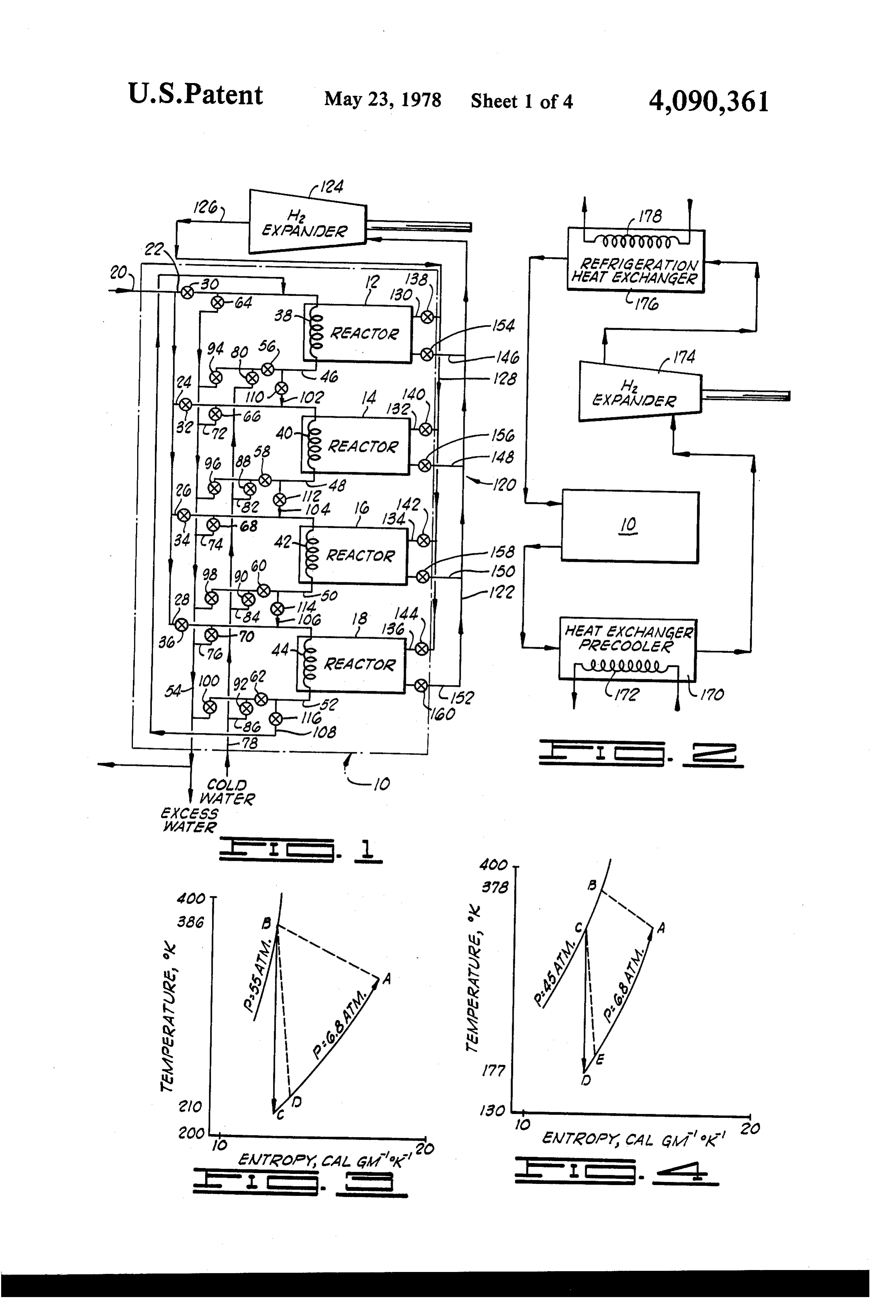
since the thermal efficiency of the primary cycle would Additional objects and advantages of the present be greatly improved by the lower heat sink, and the heat necessary to drive the absorption cycle by the operation invention will become apparent as the following de of the hydride reactor would be readily available from tailed description of preferred embodiments of the in lower temperature thermal energy (waste heat, etc.). 35 vention are read in accordance with the accompanying Substantially all other types of existing power plants drawings which illustrate such preferred embodiments. using conventional power cycles could also benefit BRIEF DESCRIPTION OF THE DRAWINGS greatly from the use of the auxiliary absorption cycle constituted by the HDH system, and near doubling of FIG. 1 is a schematic flow diagram of a hydride the power output using the same amount of fuel that is 40 reactor system used in carrying out, in a continuous now used could be obtained in many instances. fashion, the HDH cycle of the present invention. FIG. 2 is a schematic flow diagram illustrating the
BRIEF DESCRIPTION OF THE PRESENT manner in which pressurized hydrogen from the hy INVENTION dride reactor system can be utilized for effecting heat The present invention comprises methods and appa 45 ing, work production and refrigeration in the course of ratus for utilizing an HDH power cycle in which hydro the HDH cycle.
gen gas is continuously produced at high pressure and FIG. 3 is a temperature-entropy diagram of an HDH elevated temperature in combination with various types power cycle when the hydrogen is utilized solely for of heating and cooling steps and devices, and with addi operating a turbine or the like.
tional HDH power cycles or other power cycles to 50 FIG. 4 is a temperature-entropy diagram of hydrogen more efficiently use the thermal and pressure energy of as utilized in the power cycle schematically illustrated the hydrogen yielded in the HDH power cycle. in FIG. 2.
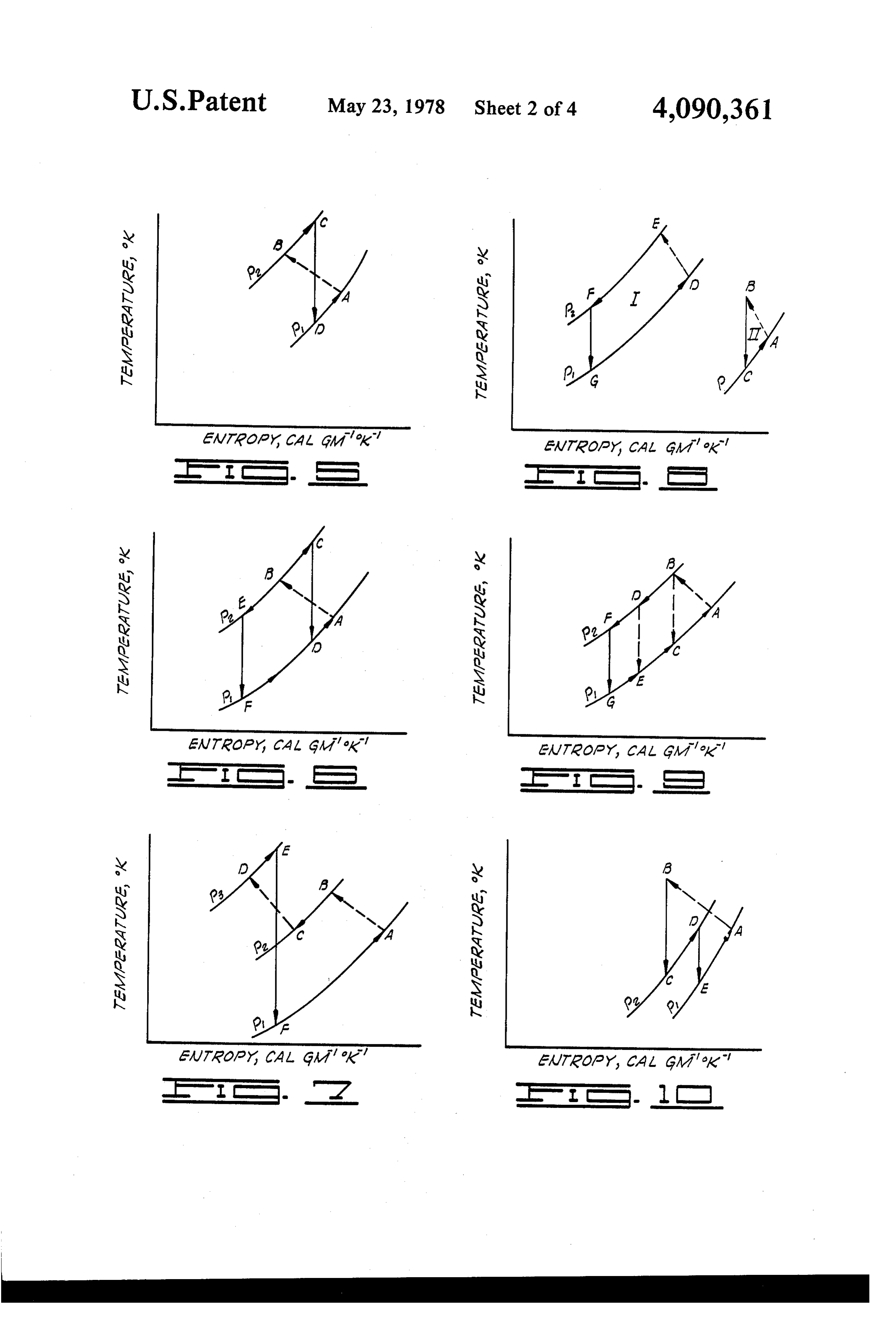
In one aspect of the invention, the HDH cycle is used FIG. 5 is a temperature-entropy diagram for hydro as an absorption cycle to provide a very low tempera gen, depicting the manner in which the compressed ture heat sink for a primary power cycle which is 55 hydrogen produced by the hydride reactors can be thereby enabled to operate at a thermal efficiency heated to increase the enthalpy thereof prior to expan which is substantially higher than is normally attainable sion through a turbine, and thereby increase the realized with such cycle. power production.
In another aspect, the HDH power cycle is improved FIG. 6 is a temperature-entropy diagram illustrating by heating the compressed hydrogen gas leaving the the manner in which the compressed hydrogen from the hydride reactor bank upon dehydriding to impart a hydride reactor can be divided into split streams for higher energy level prior to charging the hydrogen to purposes of heating prior to expansion, and concur an expansion device for producing work. rently imparting heat to an external system. In another aspect of the invention, the compressed FIG. 7 is a temperature-entropy diagram illustrating hydrogen discharged from the hydride reactor bank is 65 the manner in which a plurality of hydride reactors split into two streams, with one undergoing heating containing different hydride materials characterized by before charging to the expansion device, and the other differing equilibrium temperatures and pressures can be being cooled by yielding part of its heat through a heat used in a complementary fashion to improve the effi
Page 8
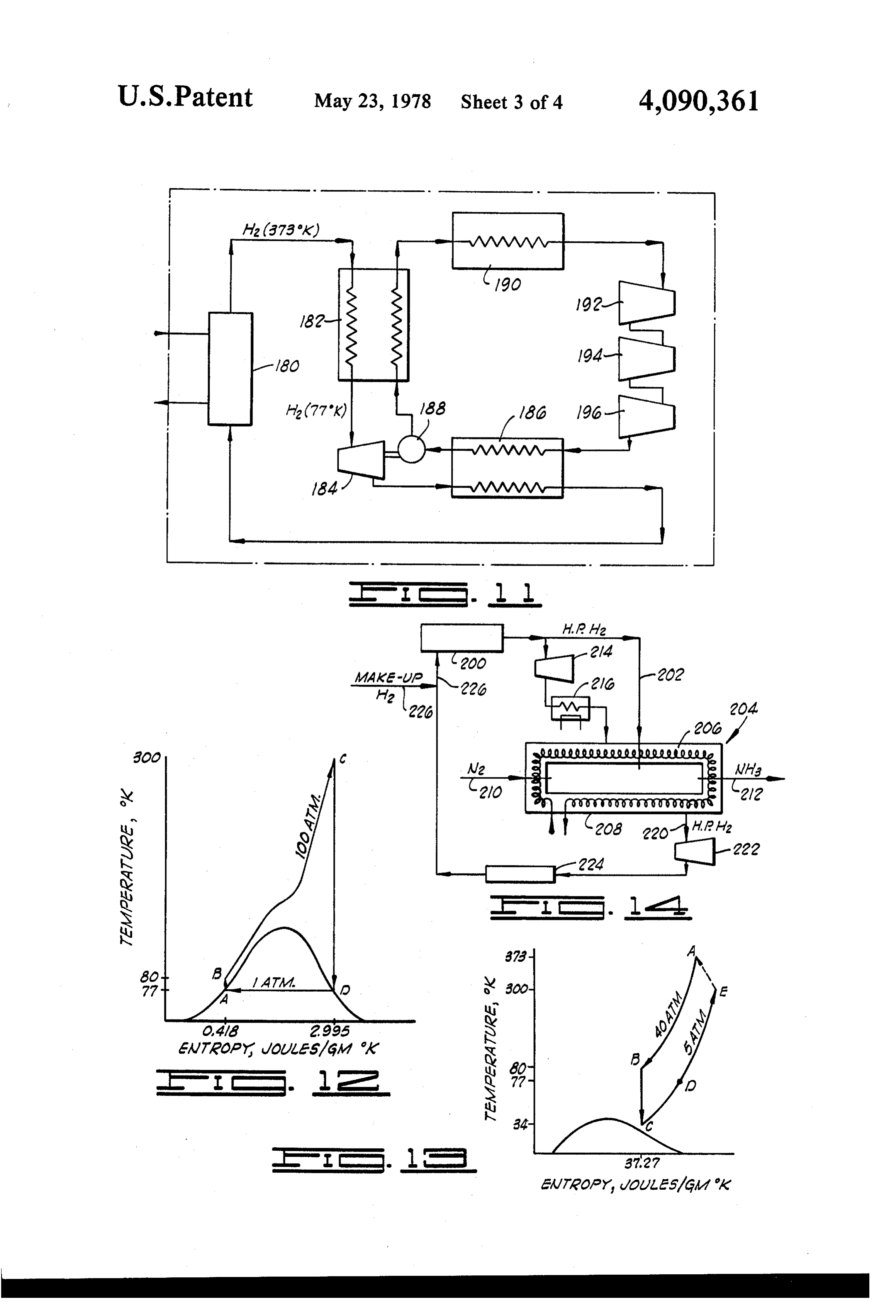
ciency and work developed upon expansion of the com tively. These short conduit sections contain valves 88, pressed hydrogen gas. 90 and 92, respectively. A valve 94 is positioned in the FIG. 8 is a temperature-entropy diagram illustrating branch conduit 46 between the point of connection of the combination of a plurality of HDH power systems the manifold conduit 54 to the branch conduit 46, and through a common heat exchange means. the point of connection of the latter conduit to the re FIG. 9 is a temperature-entropy diagram illustrating turn manifold conduit 54. Similarly, valves 96, 98 and the manner in which cascading of heat exchange can be 100 are positioned in the branch conduits 48, 50 and 52 used to improve the refrigeration attainable using the between the point of connection of the short conduit HDH power cycle. sections 82, 84 and 86 with these respective branch FIG. 10 is a temperature-entropy diagram illustrating 10 conduits 48, 50 and 52, and the points where the branch the manner in which the hydrogen exhausting from a conduits are connected to the return heat exchange first expansion device in an HDH power cycle can be fluid manifold conduit 54. Residual heat exchange fluid regeneratively heated so that further power may be conduits 102,104,106 and 108 are provided in the heat extracted from a second expansion device. exchange medium circulation system, with the conduit FIG. 11 is a schematic flow diagram illustrating the 15 102 extending between the branch conduit 46 and con manner in which the pressurized hydrogen from a hy taining valve 110. Conduit 104 extends between the dride reactor bank can be utilized to provide a very low branch conduit 48 and the branch conduit 26, and con temperature heat sink for a primary Rankine power tains a valve 112. Conduit 106 extends between the cycle utilizing nitrogen. branch conduit 50 and the branch conduit 76 and con FIG. 12 is the temperature-entropy diagram for nitro 20 tains the valve 114. Finally, the conduit 108 intercon gen as the nitrogen is utilized in an ideal Rankine cycle nects the conduit 52 with the conduit 20 and contains a corresponding to the power cycle shown in FIG. 11. valve 116.
FIG. 13 is the temperature-entropy diagram for hy In general, the heat exchange medium circulation drogen as used in the auxiliary HDH power cycle em system functions to convey hot water or the like (a low ployed in the system shown in FIG. 11. 25 thermal energy heat exchange medium) to the several FIG. 14 is a schematic flow diagram illustrating the heat exchange coils or loops 38-44 via the branch con use of the HDH power cycle in the production of am duits 22, 24, 26 and 28 in alternating or sequential opera monia. tion, and to convey spent heat exchange medium con FIG. 15 is a schematic flow diagram illustrating the taining residual heat from one of the reactors 12-18 to a use of the HDH power cycle in the production of re 30 second of the reactors located downstream therefrom, frigeration, employing cascaded heat exchangers and after a portion of the heat from the heat exchange me work-producing expansion devices to produce ultra dium has been used for heating the upstream reactor to cold hydrogen gas. a predetermined temperature. The cold water manifold FIG. 16 is a schematic flow diagram, similar to FIG. conduit 78 functions to convey water at relatively low 15, illustrating another method of cascading for the 35 temperature to the several heat exchange coils or loops purpose of producing very cold hydrogen gas for re 38-44 in alternating sequence with respect to the con frigeration purposes. veyance of the hot heat exchange medium from a suit able source to these same heat exchange loops. The
DETALED DESCRIPTION OF A PREFERRED return heat exchange manifold conduit 54 functions to EMBODIMENT OF THE INVENTION collect the spent heat exchange medium at relatively FIG. 1 of the drawings illustrates a hydride reactor low temperature after it has been circulated through the system or bank 10 constructed in accordance with the heat exchange loops or coils 38-44 in the reactors present invention, and including a plurality of hydride 12-18, and can be used to return at least a portion of this reactors 12, 14, 16 and 18. A low grade thermal energy heat exchange medium to the system or systems from source, such as geothermal water, spent steam from a 45 which it is derived for reuse. The manner in which the turbine used in a nuclear reactor, or any other suitable heat exchange medium circulation system as thus identi source of heat from a flowing fluid (solar energy can be fied and described, is employed in providing heat in the ultimate heat source), is charged to the reactor bank alternating cyclical fashion to the reactors 12-18 is 10 through a conduit 20 and is admitted, in a controlled described in detail in our U.S. application Ser. No. sequence, to the reactors 12-18 through branch con 50 553,248, which teaching and disclosure is incorporated duits 22, 24, 26 and 28 via valves 30, 32, 34 and 36. The herein by reference.
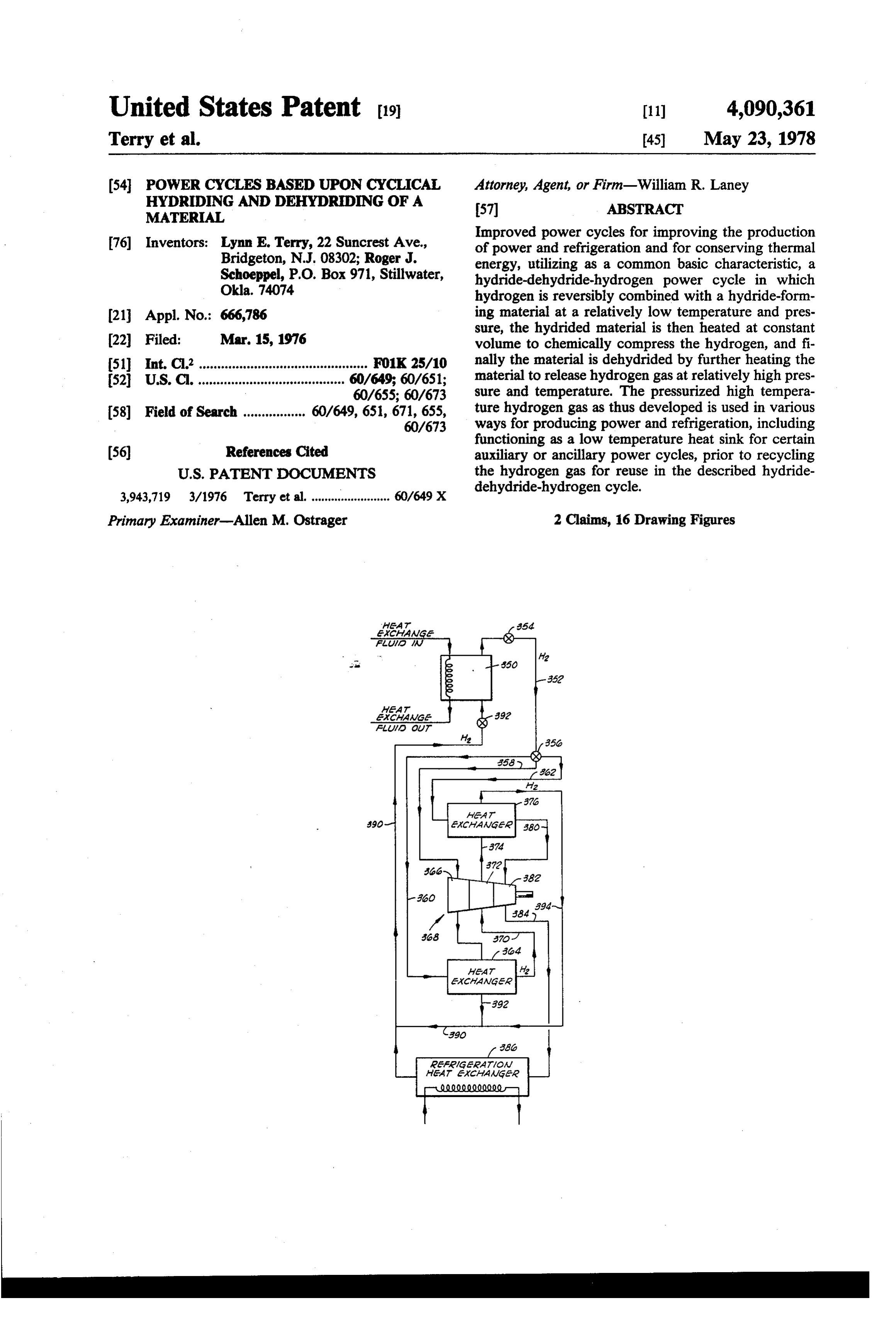
branch conduits 22-28 are respectively connected to A hydrogen gas power loop is utilized in conjunction heat exchange loops 38, 40, 42 and 44 located in the with the reactor bank and is designated generally by reactors 12-18, respectively. The heat exchange loops reference numeral 120. The hydrogen gas power loop 38-44 are also connected through branch return con 55 120 includes a collection manifold conduit 122 for con duits 46, 48, 50 and 52, respectively, to a return heat tinuously receiving hydrogen gas under pressure in a exchange fluid manifold conduit 54 through valves 56, selected and alternating cyclical fashion from the reac 58, 60 and 62, respectively. The return heat exchange tors 12-18. The manifold conduit 122 delivers the hy fluid manifold conduit 54 is connected to each of the drogen gas at elevated temperature and pressure to a branch conduits 22, 24, 26 and 28 through a plurality of 60 power producing hydrogen expander device, such as a respective valves 64, 66, 68 and 70. It will be noted that turbine 124, through which the hydrogen is expanded to the latter three valves are located in short conduit sec cause rotation of the turbine and to produce shaft tions 72, 74 and 76 which connect the return manifold power. The hydrogen gas, at reduced temperature and conduit 54 to the branch conduits 24, 26 and 28. pressure, is discharged from the turbine 124 into a con A cold water charging manifold 78 is connected at 65 duit 126 forming a portion of the hydrogen gas power one end through a valve 80 to the branch conduit 46, loop, and is returned via hydrogen gas charging mani and is connected by a series of short conduit sections 82, fold 128 to a series of branch conduits 130, 132, 34 and 84 and 86 to the branch conduits 48, 50 and 52, respec 136 to the reactors 12-18, respectively. The branch
Page 9
conduits 130-136 contain, respectively, valves 138, 140, gen gas at such equilibrium conditions. As further ex 142 and 144. For the purpose of conveying hydrogen plained in our copending application, the reactor bank gas at high temperature and pressure from the reactors 10 utilized in developing the HDH power cycle is oper 12-18 to the collection manifold 122, a plurality of ated so that the reactors 12-18 are charged, and the branch conduits 146, 148, 150 and 152 are provided, and material therein undergoes hydriding, in staggered or contain valves 154, 156, 158 and 160, respectively. out-of-phase sequence. Each of the reactors contains a Each of the reactors 12-18 is a closed vessel which, in hydridable material, or differing hydridable materials the illustrated embodiment of the invention, contains a having different equilibrium temperature and equilib solid material capable of reacting with hydrogen gas at rium pressure characteristics.
relatively low temperature and pressure to form hy 10 It is convenient to discuss the operation of the reactor dride compounds. Preferably the solid material used in bank 10 in terms of the initial phase of the HDH cycle the reactors for formation of the hydride is capable of being that at which the hydridable material is in a cold, reacting with hydrogen to form a stable hydride at a deactivated state. "Cold' in this instance refers to, in temperature below about 150 F and a pressure which general, a temperature lower than that required for does not exceed 10 atmospheres. Where a plurality of 15 hydriding and, generally, ambient temperature or different hydride materials are used in certain embodi lower. For the purpose of bringing a reactor to this state ments of the invention, as hereinafter described, the of lowered temperature, cold water or another suitable, equilibrium temperature and pressure of the several relatively low temperature heat exchange medium is hydrides formed by reaction with hydrogen may vary circulated through the heat exchange coil located in considerably as between the different hydride materials 20 each of the reactors when the reactor is to be brought to used in different reactors within the system. Materials this phase of the HDH cycle. The water is, of course, suitable for use in the reactor include, but are not lim brought to the exchange coils in the reactor through the ited to, nickel-magnesium alloys, iron-titanium alloys, cold water manifold 78, and, as explained in our co copper-magnesium alloys, vanadium metal, lanthanum pending application, is introduced to the reactors in nickel compounds, lathanum-cobalt compounds, scan 25 staggered or out-of-phase sequence. Concurrently with dium metal, scandium-cobalt compounds and com the cooling of the reactor in the manner described, pounds of the generic formula RTs, where R is a lantha hydrogen gas which has been exhausted through a tur nide ion, and T is a 3d-transition metal. A very suitable bine 124 or other work producing device is charged to material, and one preferred for ordinary basic use of the the reactor which is at this phase in the cycle. At this HDH power cycle, is an iron-titanium alloy. Where this 30 time, the hydrogen gas is at relatively low pressure and alloy is used, it can contain from about 20 weight per temperature.
cent to about 65 weight percent of iron, with the re The hydrogen entering a reactor at this cold phase of mainder being substantially entirely titanium. the cycle combines chemically with the hydridable The mechanism by which the solid hydride-forming material in the reactor in an exothermic reaction which materials combine chemically with hydrogen gas at 35 would commence to elevate the temperature in the relatively low temperatures and pressures, and can then reactor above the equilibrium temperature for the par be activated to produce pressured hydrogen gas, is set ticular hydride which is formed were it not for the forth in detail in our copending application Ser. No. cooling by the coolant of manifold 78. Production of the 553,248. Typically, the solid materials utilized in the hydride continues with controlled temperature until the reactors are materials which will combine chemically equilibrium state is reached in which the hydride is with hydrogen gas at relatively low temperatures and saturated with respect to hydrogen at substantially that pressures to form a hydride. The hydrides which are pressure at which the hydrogen is introduced to the formed by such chemical reaction may contain varying reactor and at a temperature which is the equilibrium atomic ratios of hydrogen to the other elements in the temperature which is characteristic of the particular hydride, depending upon the pressure and temperature 45 hydride produced. This phase of producing the hydride at which the hydride reaction occurs. Various equilib by the exothermic reaction is illustrated by the state A rium states of the hydride exist in which differing in F.G. 3.
amounts of hydrogen are chemically bound in the hy The valving used in the reactor bank 10 is then dride molecule, with such amounts depending upon the changed to cause the material in the reactor to undergo equilibrium temperature and pressure utilized. In any 50 activation. This is accomplished by circulating a rela case, the selected equilibrium pressure and temperature tively warm or hot heat exchange medium to the heat employed will depend upon the specific hydriding char exchange coil in the particular reactor which is at this acteristics of the hydridable material used, and the par stage of the cycle, with such heat exchange medium ticular heat sources available for supplying heat for the being ultimately supplied via the conduit 20, but being purpose of bringing the hydride up to the equilibrium 55 preferably directly derived as exhaust heat exchange temperature, and then activating the hydride prior to medium from an upstream reactor which is undergoing release of the pressurized hydrogen gas. Also, as will be dehydriding in the manner hereinafter described. apparent from the following discussion, selection of a The passage of the relatively hot water through the particular hydridable material and equilibrium pressure coil of the reactor in which the hydrided material is and temperature will depend upon the application or being activated increases the temperature in the reactor utilization to be made of the HDH power cycle, and from the equilibrium temperature to a temperature sub more particularly, the use to be made of the pressurized stantially above the equilibrium temperature. Concomi hydrogen gas developed thereby. tantly, the pressure is increased very substantially As explained in our copending application Ser. No. within the reactor. The volume is, of course, retained 553,248, it is generally desirable to utilize hydridable 65 constant. This activation phase of the HDH cycle is materials which, upon hydriding, develop the highest represented by the line AB on the temperature-entropy equilibrium pressure at the lowest equilibrium tempera diagram depicted in FIG. 3, and the attainment of the ture and combine with the maximum amount of hydro fully pressurized status upon completion of activation is
Page 10
represented by point B on this diagram. It is here that bank 10 are accomplished in an alternating or staggered the advantage of the HDH procedure can be perhaps sequence. In this way, pressurized hydrogen gas is being most appreciated. By the use of a relatively low temper discharged from at least one of the reactors 12-18 into ature thermal energy source, the phenomena of chemi the collection manifold 122 at all times, and the supply cal compresssion of the hydrogen gas occurs during of pressurized hydrogen is thereby rendered substan activation as a result of the constant volume limitation tially continuous.
imposed on the system which produces a source of very One application of the HDH cycle carried out as thus highly compressed hydrogen gas. The compressed hy described is illustrated in FIGS. 2 and 4 of the drawings. drogen can then be used for a number of useful applica In FIG. 2, the reactor bank 10 is schematically illus tions of the complete HDH power cycle, as will be 10 trated. The flow diagram further portrays the com hereinafter explained. Of course, in some instances, it is pressed hydrogen gas developed in the reactor bank on desirable to employ hydride-forming materials which a substantially continuous basis as being directed have a higher equilibrium temperature and require a through a suitable conduit to a heat exchange precooler fluid having considerably higher thermal energy in 170. In the heat exchange pre-cooler 170, the hydrogen order to attain a much higher post-activation phase 15 gas from the reactor bank 10, at relatively high tempera temperature. ture and pressure, undergoes heat exchange with an The next phase of the HDH cycle undergone by each external fluid flowing through a heat exchange loop or one of reactors 12-18 in the course of cycling the reac coil 172 to impart a portion of the heat of the hydrogen tor is the dehydriding phase. As explained in our co gas to the external fluid. After yielding a substantial pending application, at this time the appropriate one of 20 portion of its heat to the external liquid passed through the valves 154-160 are opened to release the pressurized the heat exchange coil or loop 172, the hydrogen gas, hydrogen gas from that reactor which has been cycled still at high pressure, is expanded through the turbine through the activation phase so as to release pressurized 174 to substantially reduce the pressure and to concur hydrogen gas to the collection manifold conduit 122. At rently reduce the temperature very significantly. the same time that hydrogen is released from the reactor 25 Cold hydrogen from the turbine 174 is then passed to the collection manifold conduit 122, a relatively hot through the refrigeration heat exchanger 176 in which heat exchange medium, passed to the reactor bank 10 an external heat exchange medium is circulated through from the conduit 20, is admitted, by suitable manipula a coil 178. This may, for example, be a gas which is to tion of the included valving, to the heat exchange coil of be liquefied by passage through the heat exchange coil that one of the reactors which is in the dehydriding 30 178, and particular reference is hereinafter made to the phase. The hydrogen gas from the collection manifold utilization of a heat exchanger of this type employing 122 can then be used in various ways, several of which the cold hydrogen gas to provide a low temperature are hereinafter described and constitute aspects of the heat sink in a primary power cycle utilizing nitrogen present invention. For purposes of typical illustration, gas. In the heat exchanger 176, the cold hydrogen gas the compressed hydrogen is shown in FIG. 1 as being 35 absorbs heat from the heat exchange medium passed passed to a hydrogen expander device such as the tur through the coil 178 to refrigerate this medium. In the bine 124. Here the compressed hydrogen is expanded course of undergoing heat exchange, the temperature of through the turbine to produce shaft power. Such ex the hydrogen is elevated to some extent, and thus by the pansion reduces the pressure of the hydrogen gas, and use of the heat exchanger 176, the hydrogen which is to concurrently cools it to the temperature at which it is 40 be subsequently recharged to the hydride reactors is reintroduced to the reactor upon recommencement of advanced toward the elevated equilibrium temperature the HDH cycle. Such expansion through the turbine is which is attained in the HDH cycle.
shown by the actual or practical expansion line BD on The temperature-entropy relationship of hydrogen the temperature-entropy diagram in FIG. 3. This line during the several phases of the HDH cycle carried out may be compared with the isentropic expansion line BC 45 in the manner schematically illustrated in FIG. 2, is on the same Figure, which latter line represents the shown in FIG. 4 of the drawings. The line BC thereon ideal recovery of energy from the hot pressurized hy depicts the drop in the temperature of the hydrogen gas, drogen gas upon expansion through a turbine. and the reduction in its entropy, occurring as the hydro Continuing to consider a single reactor undergoing gen gas is passed through the heat exchanger pre-cooler phase changes in the course of the HDH power cycle, 50 170. The practical expansion line on the temperature pressurized hydrogen continues to be released from the entropy diagram is illustrated by the dashed line C-E, hydride bed at a substantially constant pressure, as the and the refrigeration by the line E-A. It will be appreci hot heat exchange medium is circulated through the ated, of course, that the increase in temperature and heat exchange coil therein, until substantially all of the entropy during the refrigeration is attained through the hydrogen has been chemically disassociated from the 55 use of the refrigeration heat exchanger 176, which in hydride, and all of the hydrogen previously chemically creases the temperature of the hydrogen gas over that combined in the hydride is released as free hydrogen. which obtains in the gas discharged from the turbine After dehydriding has been completed, the temperature 174. It will be perceived from the description of this in the reactor is decreased, and complete depressuriza mode of usage of the HDH power cycle that the cycle tion is brought about by circulating a relatively cool 60 can be used to provide, concurrently, the development heat exchange medium through the coil therein from of shaft power by expansion through a turbine, and also the cold water manifold 78. The reactor is thus pre heating and cooling.
pared for the introduction of cold hydrogen gas thereto In some instances, an increase in power production is from the charging manifold 128 and the recommence desirably obtained by further heating the compressed ment of the HDH cycle. 65 hydrogen gas produced in the reactor bank 10 prior to As explained in our copending application, the de expanding it through a turbine or other expansion de scribed four phases of the HDH cycle as they are car vice. Where the process is carried out in this manner, ried out in each of the reactors 12-18 within the reactor the activation stage is represented by the line A-B on
Page 11
FIG. 5. Upon completion of activation, the hydrogen gen gas can also be either heated or cooled after leaving gas discharged during the dehydriding phase is initially the second hydride bed, and prior to expansion through passed through a heat exchanger in which the hydrogen the turbine.
gas is further heated at constant pressure, P, as con A system in which two hydridable materials having trasted with cooling of the hydrogen gas as effected in differing equilibrium states are employed in series flow the heat exchanger pre-cooler 170 shown in FIG. 2. The in the manner described is characterized by a power entropy of the hydrogen is thereby increased from state cycle having the temperature-entropy characteristics B to state C as shown in FIG. 5. Subsequent expansion illustrated in FIG. 7. The hydride material having the through the turbine to pressure P, resulting in in lower equilibrium temperature and pressure accepts creased production of power due to the greater initial 10 hydrogen and becomes fully hydrided at state A (pres thermal energy of the charged hydrogen, is shown by sure, P). It is then activated to pressure P by further the line CD in FIG, 5. heating, and following activation, the hydrogen is re The improvement obtained by the heating of the leased by dehydriding at state B. If the released hydro compressed hydrogen gas prior to expansion through gen is cooled, for example, to state C, it may then be fed the turbine has the further advantage of permitting a 15 to a second hydridable material which is selected to more efficient and greater energy utilization through have a substantially higher equilibrium pressure (P) the conservation of higher enthalpy fluids. This is ac than the first hydridable material. Alternatively, a hy complished by substituting a relatively low enthalpy dridable material may be used in the second reactor fluid as the thermal energy source during the activation which has both a higher equilibrium temperature and and dehydriding phases in the HDH cycle, thereby 20 pressure than the hydridable material first subjected to reserving the needed higher enthalpy heat exchange hydriding, in which case it may not be necessary to fluid for use in heating the compressed hydrogen from pre-cool the compressed hydrogen gas released from state B to state C prior to expansion through the turbine. the first reactor prior to its introduction to the second Another useful application of the HDH cycle entails reactor.
splitting or dividing of the compressed hydrogen leav 25 In any event, assuming that the equilibrium pressure ing the reactor bank 10, followed by the direction of and temperature of the second hydridable material are one of the two resulting streams to a heating zone in represented by the point C on the FIG. 7 diagram, after which this stream is heated prior to expansion through this material is hydrided to equilibrium, it can be acti the turbine, and the passage of the other of the two vated by further heating to bring the temperature and compressed hydrogen streams through a heat exchange 30 entropy of the chemically compressed hydrogen gas to Zone in which the compressed hydrogen yields up a state D. At this point, dehydriding of the second bed is portion of its heat for heating a cooler external fluid. commenced, and the compressed hydrogen gas is re The treatment of the two streams in this fashion is rep leased at pressure P from the bed, and may be either resented by the lines BC and BE, respectively, on the cooled, or as illustrated in FIG. 7, heated to state E temperature-entropy diagram of FIG. 6. The process 35 prior to passing the compressed hot hydrogen gas carried out in this fashion allows the construction of through a turbine or other expansion device. Expansion separate power production and refrigeration systems, through the turbine causes substantial cooling of the utilizing compressed hydrogen from a single reactor hydrogen gas, and a relatively greater production of bank source, and also allows energy to be conserved in power as represented by the expansion line E-F in FIG. obtaining both heating and refrigeration and enhanced 7 power production in this fashion. It is advantageous, at times, to utilize some of the It is frequently desirable and advantageous to use a thermal energy developed in the hydriding phase in the plurality of differing hydride materials and separate course of an HDH cycle carried out in one system for reactors within the same system in order to develop heating hydrogen gas or a reactor bed in a second inde compressed hydrogen of a higher energy content prior 45 pendent system. Thus, following the activation phase, to expansion through a turbine so as to obtain greater and upon dehydriding of one reactor bed in one system, production of power, and also enhanced refrigeration the hot compressed hydrogen gas may be passed in heat from the cold exhaust from the turbine. In such cases, exchange relation to hydrogen gas being circulated in a one of the hydride materials will have a lower equilib second system utilizing the HDH cycle in order to rium temperature and pressure than the other, and thus SO enhance the overall thermal efficiency with which the will accept hydrogen at a lower temperature and will two systems are operated. This relationship is shown in reach equilibrium at a lower pressure prior to the acti the FIG. 8 diagram in which a hydridable material in a vation stage. Following activation of this hydride, the first system, I, is activated from state D to state E, and hydrogen, in a compressed state and at the higher dehy is then dehydrided to release the hot compressed hydro driding temperature, can be released, and after tempera 55 gen gas. The gas as thus produced is then passed in heat ture adjustment, such as by cooling, it can be passed to exchange relation to a reactor bed in a second system II a second bed of hydridable material which, as a result of in order to provide all or a portion of the heat required a higher equilibrium temperature and pressure of the to activate the hydride in such bed from state A to state hydride material formed, can accept the compressed B. The compressed hydrogen gas in the first system hydrogen gas at higher temperature and pressure in thereby undergoes cooling from state E to state F, after order to form the hydride at the different equilibrium which it is expanded through a turbine to produce state. After hydriding the second hydridable material to work, and its pressure drops from P to P in the first its equilibrium state, the hydride is then heated to acti system. The primary advantage which is realized from vate it, and after completion of the activation stage, the the concurrent operation of two systems inter-related in highly compressed hydrogen gas can be released by 65 the manner described is the production of a greater dehydriding in the manner previously described, and power output through the conservation of input energy. expanded through a turbine to provide the enhanced The same or different hydride materials can, of course, production of power. Of course, the compressed hydro be used in the two systems.
Page 12
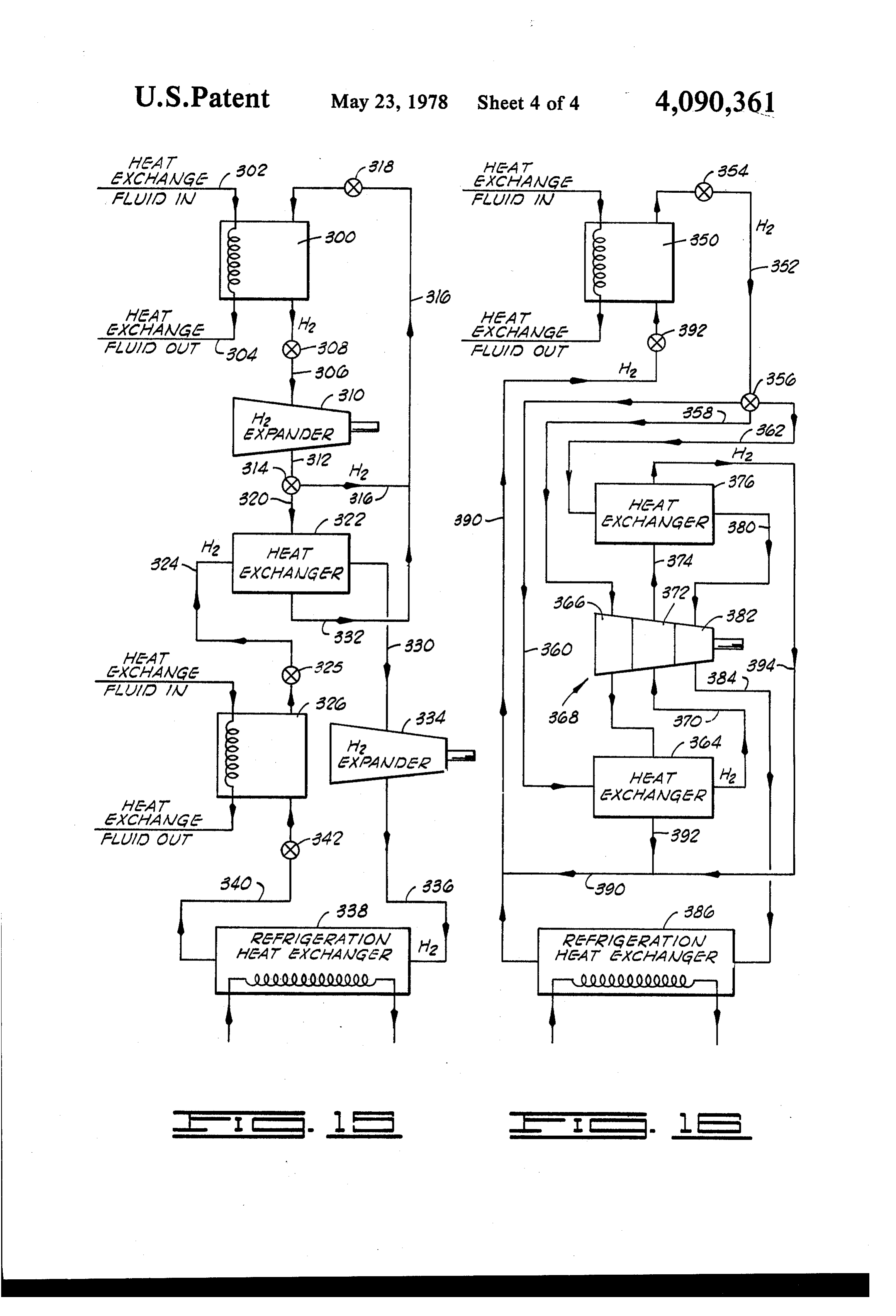
It is also advantageous, at times, to utilize a second tor 300 passes through a conduit 306 containing control HDH cycle to cool the hydrogen being circulated valve 308 to a power-producing expansion device 310, through the precooler 170 of FIG. 2 of a first HDH such as a turbine, where the hydrogen gas undergoes cycle, said second cycle being used to provide the extra expansion and is reduced substantially in temperature. cooling needed to condense hydrogen within the first The stream of cold hydrogen gas from expansion device cycle or to provide refrigeration for a first cycle operat 310 is discharged through a conduit 312 and, by means ing at a lower temperature. of a proportioning valve 314, is split into two streams, Instead of passing the heated hydrogen gas generated one of which passes through a conduit 316 and is re in the reactor of the first system at state E in direct heat turned to the reactor 300 in a controlled sequence, as exchange relation to either the reactor in the second 10 hereinbefore described, with control being effected system, or in heat exchange relation to the hydrogen gas through the utilization of a suitable control valve 318. of the second system, an intermediate heat exchange The second portion of the stream of hydrogen gas medium can be passed in a closed loop in heat exchange discharged from the expander 310 is directed by the relation to the hot hydrogen gas produced upon dehy proportioning valve 314 into a conduit 320 and from driding the reactor in system I, and in heat exchange 15 this conduit passes into a heat exchanger 322. In the heat relation to the hydrogen gas used in the second system, exchanger 322, the cold hydrogen gas from the expan or with respect to a reactor employed therein. This can der 310 abstracts heat from a stream of compressed entail the use of a heat exchanger pre-cooler of the sort hydrogen flowing into the heat exchanger 322 via con illustrated in FIG.2 for abstracting a portion of the heat duit 324 containing control valve 325 from a second of the hot compressed hydrogen gas yielded from a 20 hydride-dehydride reactor 326. The thus cooled hydro reactor bed of system I at state E, and carrying the gen gas originating at the reactor 326 is discharged from received thermal energy, by such external, closed heat the heat exchanger 322 via a conduit 330, and the exchange loop to the point of yielding up the heat to a warmed hydrogen gas resulting from the heat exchange reactor bed of system II. in the heat exchanger 322 is passed through a conduit The HDH power cycle can be beneficially utilized in 25 332 and merged with the hydrogen being returned to a system which employs cascaded heat exchange. By the reactor 300 via conduit 316. employing such cascading, improved refrigeration uti lizing the compressed hydrogen gas can be realized. through a secondgas
Cold hydrogen from the conduit 330 is expanded power-producing expansion device
Cascading of the type described is practiced by direct 334, such as a turbine, and by such expansion is further ing the cold exhaust from the turbine or other expansion cooled to an even lower temperature. The very
cold means through one side of a heat exchanger where the hydrogen gas emerging from the expander 334 is passed cold exhaust in the turbine is utilized to pre-cool the through conduit 336 to a refrigeration heat exchanger inlet hydrogen being directed into the turbine. The 338 where it is employed in a refrigeration function for effect of such cascading in improving the obtainable refrigerating an external fluid which is charged to the refrigeration will be better understood by referring to 35 refrigeration heat exchanger. After accomplishing the the portrayal in FIG. 9 of the temperature-entropy refrigeration function, hydrogen gas from the refrigera characteristics of the hydrogen gas utilized in such a tion heat exchanger 338 is recycled to the reactor 326 system. Dehydriding of the reactor is commenced at via a conduit 340 which contains the control valve 342 state B. The hydrogen gas is then expanded through the which is operatively sequenced as required by the hy turbine to state C. The hydrogen is then recycled and 40 dride-dehydride-hydrogen cycle. hydriding is carried out from state C to state A, fol lowed by activation to state B. The cold hydrogen tained, and in accordancebywith
It will be perceived that the cascading effect ob the thermodynamic exhausted from the turbine during the initial expansion, considerations depicted in FIG. 9 of the drawings, it is B-C, is passed in heat exchange relation to the hydrogen subsequently produced upon dehydriding at state B so 45 possible to obtain a high magnitude of reduction in the as to pre-cool the off-coming hydrogen to state D prior temperature of the hydrogen gas produced by the sec to expansion through the turbine to state E. The colder ond reactor 326, and thereby to provide an excellent hydrogen thus produced after expansion through the refrigeration capability.
turbine is again used for pre-cooling hydrogen subse In FIG. 15 of the drawings, a slightly different quently expanded through the turbine to lower its tem 50 scheme of cascading is illustrated. A hydride reactor perature to state F. It will thus be seen that the cycle of 350 is here provided for the purpose of producing cascading and reduction of the input temperature of the highly compressed hydrogen gas in the manner herein hydrogen charged to the turbine can be repeated so as before described. The compressed hydrogen gas passes to ultimately cascade the temperature to some relatively through a conduit 352 containing control valve 354 to a low equilibrium temperature. At such low equilibrium 55 distributing valve 356.
temperature, very cold hydrogen gas is yielded upon The valve 356 may function in either of two ways. It expansion through the turbine, with the result that im may, by proper manipulation of its operative position, proved refrigeration can be obtained with this turbine be used to selectively direct hydrogen gas into a se exhausted hydrogen. lected one of the conduits 358, 360 or 362, or it may be Examples of two such cascaded systems as they are 60 made to function as a proportioning valve which dis employed in achieving enhanced refrigeration are de tributes proportioned quantities of the total hydrogen picted in FIGS. 14 and 15 of the drawings. Referring gas stream from conduit 352 into each of the conduits initially to FIG. 14, a hydride-dehydride reactor 300 of 358, 360 and 362.
the type previously herein described is provided and is For purposes of the present discussion, it will be operated on the hydride-dehydride-hydrogen cycle, 65 initially assumed that the valve 356 is used for sequen using a heat exchange medium delivered to the reactor tially and selectively directing hydrogen gas into se through a conduit 302 and discharged therefrom via lected ones of the conduits 358, 360 and 362 in a se conduit 304. Compressed hydrogen gas from the reac quence to be described.
Page 13
The valve 356 is first placed in a status such that all of which hydrogen gas released upon dehydriding of the the hydrogen gas being discharged at a given time from hydride bed (state B as shown in either FIG. 5 or 10) is the reactor 350 to the conduit 352 is caused to flow into then expanded through a turbine or other work produc the conduit 358. From this conduit, this hydrogen gas ing expansion device to state C as shown in FIG. 10. flows into the first stage 366 of a three-stage turbine The exhausted hydrogen is then regeneratively heated designated generally by reference numeral 368. After to increase its temperature from state C to state D (FIG. the passage of a pedetermined time, and the charging of 10). It will be apparent that this entails the use of a heat a first portion of the hydrogen gas produced in the exchange medium which can be at a lower temperature reactor 350 to the first stage 366 of turbine 368, the for effecting such regenerative heating of the exhausted valve 356 is shifted so that a subsequently evolved quan 10 hydrogen gas than is required to directly and immedi tity of hydrogen gas from the reactor 350 is caused to ately heat the hydrogen produced in the reactor from flow from the conduit 352 into the conduit 360. Hydro state B to state C as shown in FIG. 5. gen gas from the conduit 360 enters a heat exchanger After the hydrogen gas from the turbine exhaust has 364 where it is cooled by heat exchange with the cold been heated to state D as shown in F.G. 10, it can be hydrogen gas discharged from the first stage 366 of 15 expanded through a second turbine so that the tempera turbine 368. The cold hydrogen gas from the heat ex changer 364, which has been charged to this heat ex ture D-E.
and pressure are lowered, as shown by the line
The cycle of hydriding, activation, dehydriding changer from the conduit 360, is then discharged via and expansion are then repeated, with regenerative conduit 370 to a second stage 372 of turbine 368. The heating of the turbine exhaust again carried out as cold hydrogen gas from conduit 370 is here expanded 20 shown in FIG. 10. When the HDH cycle is practiced in through this stage of the turbine, and is discharged into a conduit 374 which is connected to a heat exchanger this fashion, it will be seen that greater total power and refrigeration is developed from the hydrogen gas as a
After the passage of a second interval of time follow result of the dual expansion through the two expansion devices. Moreover, when it is recalled that the hydrid ing the initial shifting of the valve 356 to connect the 25 ing reaction is an exothermic one, it will be perceived conduit 352 to the conduit 360, the valve is again shifted that a portion of the heat developed in the reactor bed to direct a third portion of hydrogen gas produced in as the hydridable material is hydrided from state E to the reactor 350 from the conduit 352 into the heat ex changer 376 by passage through conduit 362. In the heat state A can be used to provide a part of the heat for the exchanger 376, this third portion of hydrogen gas un 30 regenrative heating of hydrogen gas from state C to dergoes heat exchange with the very cold hydrogen state D. Thus, energy conservation is effected by mak passed through the heat exchanger from the second ing use of a portion of the heat developed upon effect stage of the turbine 368. Hydrogen gas derived from the ing the hydriding phase in the reactor. conduit 362 therefore emerges from the heat exchanger The possibility of utilizing the heat of reaction devel 376 in the discharge conduit 380 in an extremely cold 35 oped during the hydriding phase occurring in one of the condition. After it has been expanded through the third hydride reactors for regeneratively heating hydrogen stage 382 of the turbine 368, it is even further cooled gas which has been expanded through a first expansion and is charged via the conduit 384 to a heat exchanger device, as discussed in reference to FIG. 10, suggests 386 to provide excellent refrigeration. After accom another important usage of the HDH cycle. Thus, plishing its refrigerating function, the hydrogen gas 40 where two separate systems are provided, similar to the used in the refrigeration heat exchanger 386 is returned two systems earlier discussed in referring to FIG. 8, the to the reactor 350 via a manifold conduit 390 which thermal energy developed upon hydriding the reactor contains a control valve 392. It should be pointed out bed in one of the systems can be utilized for providing that the hydrogen gas streams used for cooling purposes the activation heat required for activating a hydride in in the heat exchangers 364 and 376 are also fed back into 45 a second system preparatory to commencing the dehy the manifold conduit 390 by means of branch conduits driding phase. Of course, for the thermal energy devel 392 and 394 for ultimate return to the reactor 350. oped upon hydriding of a reactor bed in the first system As an alternate mode of operation of the system to be adequate to supply the entire energy requirement shown in FIG. 15, the valve 356 may be used as a pro for effecting complete activation of a hydride bed in the portioning valve with the hydrogen flowing in the con 50 second HDH power system, the equilibrium character duit 352 proportionately divided in a desired manner istics of the two hydrides involved will, of necessity, be and introduced to the conduits 358, 360 and 362. When different so as to facilitate such heat utilization. It will this is accomplished, the cascading effected by using the further be apparent that the reactors as between which three-stage turbine 368 and the heat exchangers 364 and the described heat exchange is carried out may also be 376 connected to the first and second stages thereof is 55 located within the same system, with differing hydride carried out in a continous ongoing fashion, and the same materials utilized in the reactors to facilitate maximum excellent refrigerating effect is attained as that which is utilization of the available heat of reaction. attained when the pressurized hydrogen from the reac It will also be noted from the foregoing discussion tor 350 is sequentially charged to the conduits 358, 360 that heat is available in the spent reactor bed upon com and 362. pletion of the dehydriding phase of the HDH cycle, and The HDH cycle can be carried out in a way which, as such heat must be removed in restoring the bed to a contrasted with the enhanced or increased power pro cooler state preparatory to receiving hydrogen gas to duction obtained when the hydrogen gas is heated upon recommence the hydriding phase of the cycle. Again, release from the hydride bed in the manner shown in this heat may, at this time, be beneficially abstracted FIG. 5, does not require a heat exchange medium hav 65 from the reactor bed and used for providing the activa ing as high a temperature as that which must be used to tion heat needed for a different hydride bed, either in heat the released hydrogen from state B to state C in the same or a different system. It can also be used for FIG. 5. This is accomplished by regenerative heating in providing the heat necessary for dehydriding an acti
Page 14
vated hydride in a different reactor within the same or a heat exchanger 186 where heat is exchanged with different system. saturated nitrogen gas which is at about 1 atmosphere As previously pointed out herein, the HDH cycle can pressure and 77° K (state D on FIG. 12). At the 256 be utilized to provide a very cold heat sink in an ancil kg/hr of hydrogen mass flow rate developed upon ap lary power cycle. When work is taken out of the high 5 plication of one megawatt of thermal energy to the pressure hydrogen gas derived from the hydride reactor hydrided iron titanium powder reactor, 627 kg/hr of upon dehydriding, the gas is cooled to a very low tem nitrogen is condensed by passage through the heat ex perature. All thermodynamic cycles require a heat sink, change device 186. The heat exchange at this location and the very low temperature of the expanded hydro thus has the effect of changing the temperature-entropy gen gas developed in the HDH cycle provides an ex 10 characteristic of hydrogen to state D as shown in FIG. tremely low temperature heat sink for inclusion in a 13, and the temperature-entropy characteristic of the different thermodynamic cycle using a different work nitrogen to state A in the diagram of FIG. 12. ing fluid. The hydrogen from the heat exchanger 186 is then A system employing the low temperature heat sink recycled to the reactor bed 180 where completion of the achieved through the use of the HDH cycle is illus 15 hydriding of the iron titanium powder in the charging trated in FIG. 11, and can best be understood by refer reactors of the bank is completed, and state E of the ring to that figure in conjunction with FIG. 12. FIG. 12 FIG. 13 diagram is achieved. Activation of the hydride portrays the ideal behavior of nitrogen in a Rankine bed to state A to recommence the cycle is then achieved cycle. Beginning at stage A on the temperature-entropy by the application of heat from an external, relatively diagram, the nitrogen is a saturated liquid at 77' K and 20 low temperature thermal energy source. at one atmosphere pressure. The nitrogen is then com The saturated liquid nitrogen leaving the heat ex pressed isentropically and adiabatically to state B at change device 186 is compressed to 100 atmospheres by which it is at 100 atmospheres pressure and about 80 K. the use of a pump 188 which is driven by the turbine After compression by pumping, the nitrogen is heated 184. The nitrogen is then heated by passage through the at this constant pressure of 100 atmospheres to state C 25 heat exchanger 182 to 300 K, and can be heated to which is at 300 K. This value is selected to show that some higher temperature not shown on FIG. 12 by heat useful power can be obtained from the compressed from some external source, such as a nuclear reactor or nitrogen by merely employing ambient temperature fossil fuel heater 190. The compressed nitrogen is passed water to effect the heating required. The nitrogen is from the heater 190 to a serially staged group of three subsequently expanded isentropically and adiabatically 30 expander devices 192, 194 and 196 which extract work to state D which is saturated vapor at 1 atmosphere from the compressed nitrogen in a series of pressure pressure and 77 K. The nitrogen is then condensed to drop stages across the three devices. In this manner, the state A. The condensation of the nitrogen can be benefi nitrogen gas is decompressed and returned to state D cially effected by the use of the low temperature heat shown in the temperature-entropy diagram of FIG. 12. sink provided by the HDH cycle. 35 The foregoing discussion assumes ideality in a Ran A system which employs this principle is illustrated kine cycle using nitrogen as the working fluid, and in FIG. 11 and the temperature-entropy diagram of the using, in conjunction therewith, an HDH cycle, ideally parallel HDH cycle providing the low temperature heat operated, for the purpose of providing a low tempera sink is depicted in FIG. 13. A reactor bank of the type ture heat sink. The nitrogen in the postulated ideal Ran hereinbefore described is illustrated at 180 in FIG. 11, 40 kine cycle produces 37.4 kW of power at 0.53 thermal and highly compressed hydrogen gas is produced and efficiency. The Carnot efficiency at the temperature discharged from the reactor bank during the dehydrid employed in the described ideal Rankine cycle is 0.74. ing cycle. At this time, heat is being supplied to the The HDH cycle employed produced, ideally, 29 kW of reactor bank to dehydride the particular hydride alloy power at a thermal efficiency of 0.03, and the equivalent which is in a state of activation, and ready for dehydrid 45 Carnot efficiency would be 0.21. The Rankine cycle can ing for purposes of discussion, it may be postulated, for also be further improved by the use of appropriate com example, that a heat of one megawatt at 212 F (or 373 puter design optimization techniques to yield better K) is supplied to a hydrided iron titanium powder in one operating pressures and temperatures so as to effect a of the reactors in the reactor bank. The hydrogen equi greater production of power and refrigeration. librium presure at this temperature is 40 atmospheres, 50 In FIG. 14 of the drawings, another important appli and this point is indicated by state A on the tempera cation of the HDH cycle is illustrated. High pressure ture-entropy diagram of FIG. 13. One megawatt of hydrogen of elevated temperature is produced in a hy thermal energy supplied to the dehydriding reactor bed dride reactor bank 200. The stream of pressurized prod will release 256 kg/hr of hydrogen. .. ; uct hydrogen is split, with a portion being delivered via The released compressed hydrogen is passed from the 55 a conduit 202 to the interior of an ammonia generator reactor bank to a heat exchange device 182. Here the reactor designated generally by reference numeral 204. compressed hydrogen is cooled by heat exchange with The ammonia generator reactor 204 is provided with a liquid nitrogen entering the heat exchange device at a peripheral chamber around the central reaction zone in temperature of about 80 K. In the course of this heat the ammonia reactor, and this peripheral chamber con exchange, the hydrogen is cooled to about 80 K (state 60 fines a hydridable material forming a hydride reactor B in FIG. 13) and the nitrogen is heated to about 300K 206. The hydride reactor 206 around the periphery of (state C in FIG. 12). The hydrogen is then expanded the central reaction zone provided in the ammonia reac through a turbine or other suitable device 184 to further tor 204 will preferably also contain a suitable heat ex reduce its temperature to 34° K, and its pressure to 5 change loop 208 to facilitate control of the exothermic atmospheres (state C in FIG. 13). The 5 atmospheres 65 hydride reaction occurring therein as hereinafter ex pressure is the equilibrium pressure of the hydrogen plained. A suitable conduit 210 is provided which ex with the iron titanium powder at 300 K. The cold tends through the chamber 206 to the central reaction hydrogen leaving the turbine 184 is then passed through zone of the ammonia reactor 204 for delivering nitrogen
Page 15
gas to the reactor. Within the reactor 204, the hydrogen heating the hydride at constant volume to a tempera and nitrogen react in an exothermic reaction to yield ture above the equilibrium temperature of the hy ammonia which is discharged from the ammonia reac dride to activate the hydride by chemically com tor 204 via a conduit 212. pressing the hydrogen gas; A part of the compressed hydrogen gas from the transferring heat to the hydride and concurrently hydride reactor bank 200 is expanded through an expan initially releasing a first quantity of hydrogen gas sion device 214 and is thereby cooled to a low tempera therefrom;
ture. The low temperature decompressed hydrogen conveying said initially released first quantity of hy from the expansion device 214 is preferably passed drogen gas from the hydride to a power producing through a refrigeration heat exchanger 216 where the 10 expansion device;
hydrogen cools an external fluid and itself is warmed expanding the first quantity of hydrogen gas through preparatory to charging it to the hydride reactor 206 in said power producing expansion device to produce the external chamber formed around the ammonia reac power and cool the hydrogen gas; tor 204. In the hydride reactor 206, hydrogen reacts passing at least a portion of the cooled first quantity with a hydridable material in the manner hereinbefore 15 of hydrogen gas from the expansion device in heat described, with the heat of hydriding (exothermic heat exchange relation to a second quantity of hydrogen of reaction) being appropriately controlled by use of an gas released from said hydride after said first quan external heat exchange medium circulated in the reactor tity upon continuing to transfer heat to said hy 206 in the heat exchange loop 208. dride to reduce the temperature of said second For the purpose of providing the heat necessary to 20 quantity of hydrogen gas released from said hy activate the hydride formed in the hydride reactor 206, dride;
the exothermic heat of reaction of the hydrogen and conveying said second quantity of released hydrogen nitrogen in forming ammonia within the ammonia reac gas from the point of said heat exchange to a power tor 204 is transferred to the hydrided material in the producing expansion device; hydride reactor 206, and the same heat source can be 25 expanding said second quantity of hydrogen gas used to effect dehydriding when the pressurized hydro through said power producing expansion device to gen gas produced in the hydride reactor 206 is to be produce power and cool the expanded second released. The pressurized hydrogen gas from the reac quantity of said hydrogen gas to a temperature tor 206 is discharged via a suitable conduit 220, is ex lower than that to which said first quantity of hy panded through a turbine 222 or other suitable expan 30 drogen gas is cooled upon expansion through said sion device and the cold hydrogen is then passed expansion device;
through a refrigeration heat exchanger 224 before recy passing at least a portion of the cooled second quan cling to the hydride reactor bank 200. Since a portion of tity of hydrogen gas from said expansion device the compressed hydrogen produced in the reactor bank into heat exchange relation to a third quantity of 200 has been used to produce ammonia, it is necessary 35 hydrogen gas released from said hydride after said to add some make-up hydrogen to that which is derived first and second quantities upon continuing to from the hydride reactor 206, and this is accomplished transfer heat to said hydride; and through a make-up hydrogen conduit 226. A portion of expanding said third quantity of hydrogen gas the power produced by the turbines 214 and 222 may be through said power producing expansion device to used, for example, for pumping the ammonia to a stor 40 produce power and cool said third quantity of age facility and, if necessary, for providing the power hydrogen gas to a temperature lower than the tem necessary to deliver the nitrogen gas to the ammonia perature to which said first and second quantities of reactor 204. hydrogen gas are cooled upon expansion through From the foregoing description of the invention, it said power producing expansion device. will be apparent that the present invention provides a 45 2. A method for deriving power from a thermal en number of energy conserving power cycles which are ergy source comprising:
capable of producing enhanced quantities of work and combining hydrogen gas with a hydride-forming which utilize, in either a primary or auxiliary power material under conditions of temperature and pres cycle, the HDH power cycle hereinbefore described, sure such that a hydride saturated with, and in and described in greater detail in our copending appli 50 equilibrium with, hydrogen gas is formed; cation Ser. No. 553,248. Although various changes and heating the hydride at constant volume to a tempera modifications can be effected in the preferred embodi ture above the equilibrium temperature of the hy ments of the invention which have been herein de dride to activate the hydride by chemically com scribed, it will be understood that such changes can be pressing the hydrogen gas;
effected without departure from the basic principles 55 transferring heat to the hydride and concurrently which underlie the invention in its most fundamental releasing a first quantity of hydrogen gas there form. Changes and innovations of this type are there from;
fore deemed to be circumscribed by the spirit and scope conveying said initially released first quantity of hy of the invention, except as the same may be necessarily drogen gas from the hydride to a power-producing limited by the appended claims or reasonable equiva expansion device;
lents thereof. expanding the first quantity of hydrogen gas through What is claimed is: said power-producing expansion device to produce 1. A method for deriving power from a low-grade power and cool the hydrogen gas; thermal energy source comprising: passing at least a portion of the cooled first quantity combining hydrogen gas with a hydride-forming 65 of hydrogen gas from the expansion device in heat material under conditions of temperature and pres exchange relation to a second quantity of hydrogen sure such that a hydride saturated with, and in gas derived from a hydride saturated with, and in equilibrium with, hydrogen gas is formed; equilibrium with, hydrogen gas at such time as said
Page 16
hydride producing said second quantity of hydro through the said last-mentioned power-producing gen gas is heated to cause release of said second expansion device to produce power and cool the quantity of hydrogen gas, whereby the tempera ture of said second quantity of hydrogen gas is expanded second quantity of said hydrogen gas to reduced; 5 a temperature lower than that to which said first conveying said second quantity of released hydrogen quantity of hydrogen gas is cooled upon expansion gas from the point of said heat exchange to a pow through said first-mentioned expansion device. er-producing expansion device; and expanding said second quantity of hydrogen gas

Provenance
- Collection
- Cited prior art
- Original PDF
- patentimages.storage.googleapis.com →
- Filed
- 1976-03-15
- Pages
- 16
- Method
- pdftotext (the PDF's own text layer) + pdftoppm 300dpi page scans
- Source
- Google Patents bibliographic record
- Granted
- 1978-05-23
- Inventors
- Lynn E. Terry; Roger J. Schoeppel
- Transcribed from
- patentimages.storage.googleapis.com →