patent · US5085176
Method of and apparatus for generating and injecting hydrogen into an engine
4 February 1992
Page 1 — bibliographic record
HHHHHHH
United States Patent (19) 11 Patent Number: 5,085,176 Brinkley, III 45) Date of Patent: Feb. 4, 1992 54 METHOD OF AND APPARATUS FOR Attorney, Agent, or Firm-John J. Mulrooney
GENERATING AND NJECTING
HYDROGEN INTO AN ENGINE 57) ABSTRACT 76 Inventor: William J. Brinkley, III, 605 E. A hydrogen generating system produces hydrogen in Eastport St., Iuka, Miss. 38852 stantaneously upon contact of a catalyst and a reactant for simultaneous injection into the combustion chamber 21) Appl. No.: 633,932 of an engine. The system includes an injector having an 22 Filed: Dec. 26, 1990 ignition chamber in communication with the combus tion chamber. A catalyst is located in the ignition cham (51) Int. Cl. .............................................. FO2B 43/00 ber. During the engine intake stroke, a reactant is fed (52) U.S. C. ................................ 123/3; 123/DIG. 12 into the ignition chamber where it reacts with the cata (58) Field of Search ............................ 123/3, DIG. 12 lyst to produce hydrogen which is instantaneously (56) References Cited drawn into the combustion chamber. A spark plug
drogen in the ignition chamber and the combustion 3,970,054 7/1976 Henault et al. ............. 123ADIG. 12 chamber explodes. The location of the catalyst in the 4,033,133 7/1977 Houseman et al. ..................... 123/3 injector provides for the generation of hydrogen and its 4,037,568 7/1977 Schreiber ................................ 123/3 4,140,090 2/1979 Lindberg ................................. 123/3 immediate injection into the engine combustion cham 4,185,593 A1980 McClure ..................... 23/DIG. 2 ber for use as a fuel. Automatic regeneration of the 4,622,924 A986 Lewis.......................... 123/DIG. 2 catalyst is provided by the fuel explosion, hydrogen and 4,702,894 10/1987 Cornish ....................... 23/DIG. 12 intense heat in the ignition chamber. Primary Examiner-Andrew M. Dolinar
Assistant Examiner-M. Macy 28 Claims, 3 Drawing Sheets
Page 2
Drawing sheet — no readable text.
Page 3
Drawing sheet — no readable text.
Page 4
Drawing sheet — no readable text.
Page 5
METHOD OF AND APPARATUS FOR No. 4,547,356, to use hydrogen as a reducing agent to GENERATING AND INJECTING HYDROGEN remove the oxygen from the catalyst surface and NTO AN ENGINE thereby regenerate or reactivate the catalyst. In general, prior hydrogen generation units have
FIELD OF THE INVENTION been used to generate on-board fuel for engines, but This invention relates to a method of and apparatus there is a need to generate larger quantities of hydrogen for generating hydrogen for use as fuel in an engine, more efficiently and to more effectively inject the hy and, more particularly, to an on-board system for gener drogen into the combustion chamber of the engine. ating and simultaneously injecting hydrogen into an O Accordingly, it is an object of this invention to pro engine for use as fuel. vide a new and improved method of and apparatus for
BACKGROUND OF THE INVENTION
generating and injecting hydrogen in an engine,
It is another object of this invention to provide a new
The problems of air pollution, diminishing supply and and improved method of and apparatus for generating increasing expense have prompted efforts to develop a 5 hydrogen from water, or steam, or moist air, or hydro feasible alternative fuel to hydrocarbons, i.e., gasoline, gen and steam, on-board a vehicle. for use in all types of engines, particularly piston driven It is another object of this invention to provide a new and rotary internal combustion engines, gas turbines, and improved method of and apparatus for generating and stirling engines. The search for an alternative fuel to 20 and simultaneously injecting hydrogen fuel directly into replace gasoline as the primary fuel used in engines has the combustion chamber of an engine. for some time focused on hydrogen. Hydrogen appears It is another object of the present invention to pro to be an ideal solution to the problems inherent in the vide a new and improved method of and apparatus for use of gasoline as a fuel because hydrogen is available in generating and injecting hydrogen into the combustion water in an inexpensive and virtually inexhaustible sup chamber of an engine involving a catalytic process in ply, and, when hydrogen burns, the exhaust is pollution 25 which deactivated catalyst is reactivated by the com free water vapor.
Prior efforts towards developing hydrogen fueled bustion process in the combustion chamber. vehicles have involved both storage of the hydrogen vide a new and object
It is another of the present invention to pro improved method of and apparatus for gas on the vehicle and on-board generation of the hy generating hydrogen on-board a vehicle powered by an
drogen gas. While substantial efforts have been made to engine comprising an injector having develop hydrogen storage systems, such storage sys communicates with the compression achamber chamber which and in tens are not presently practical because of the problems cluding a catalyst from which hydrogen is generated. of hydrogen distribution to motorists and the danger posed by the storage of a substantial amount of hydro SUMMARY OF THE INVENTION gen. 35
Prior efforts to develop an on-board hydrogen gener In accordance with a preferred embodiment of the ation system have involved manifold hydrogen genera present ating invention, there is provided a hydrogen gener system including an injector mounted on the spark tors using steam or water on catalyst at high tempera tures to generate hydrogen. The hydrogen generator plug inlet of the combustion chamber of an internal unit is mounted outside the engine in heat transfer rela combustion engine. The injector has an ignition cham tionship with the exhaust manifold to use the heat gen ber which communicates with the engine combustion erated by the engine in the hydrogen generation pro chamber and which contains a catalyst, a spark plug in cess. The hydrogen is routed through the engine carbu communication with the ignition chamber, and an inlet rator and then into the combustion engine. Examples of for feeding a reactant selected from the group consist such prior manifold hydrogen generator units are U.S. 45 ing of hydrogen and steam, or steam, or water, or moist Pat. Nos. 2,295,209; 3,653,364; 4,037,568; and 4,256,060. air, into the ignition chamber during the engine intake A significant limitation on such manifold hydrogen cycle where it reacts with the catalyst to generate hy generator units is the fact that the steam or water on drogen. Part of the generated hydrogen is drawn simul catalyst process for generating hydrogen works best at taneously into the combustion chamber during the in temperatures in the super heated range which are usu 50 take cycle where it is immediately ready for use by the ally not feasible to obtain with the amount of heat gen engine. A spark plug ignites the hydrogen in the igni erated in exhaust manifolds. Accordingly, these mani tion and combustion chambers and starts the power or fold units are either limited by the quantity of hydrogen expansion cycle of the engine. generated or must include supplemental heating means The injector housing is insulated from the water to provide the heat required to reach the super heated 55 cooled engine block, whereby the injector retains the temperatures, thereby adding to the cost and decreasing maximum amount of the extraordinary heat generated the efficiency of such units. Manifold hydrogen genera by the combustion of hydrogen so that the injector and tor units are mostly used as generators of hydrogen for the catalyst therein are heated to super heated tempera use as a supplemental fuel with gasoline. tures at which the invention operates more efficiently. Another major problem with manifold hydrogen At the super heated temperatures, hydrogen is gener generator units is catalyst deactivation whereby the ated in the injector by the dissociation of water, steam, surface of the catalyst becomes oxidized and inopera or noist air, into hydrogen and oxygen and by the liber tive to generate hydrogen until it is rendered active, i.e., ation of hydrogen from water, steam, or moisture by an reactivated, by removal of the oxidation. Prior tech oxidation process between the water, steam, or mois niques for reactivating the deactivated catalyst include 65 ture, and the catalyst. The result is the generation of replacing the catalyst, e.g., U.S. Pat. No. 2,295,209 and hydrogen adjacent to the combustion chamber and the 3,653,364; or physically removing the oxidation by simultaneous introduction of a portion of the generated brushing or other physician contact or agitation as in hydrogen into the combustion chamber where it is im
Page 6
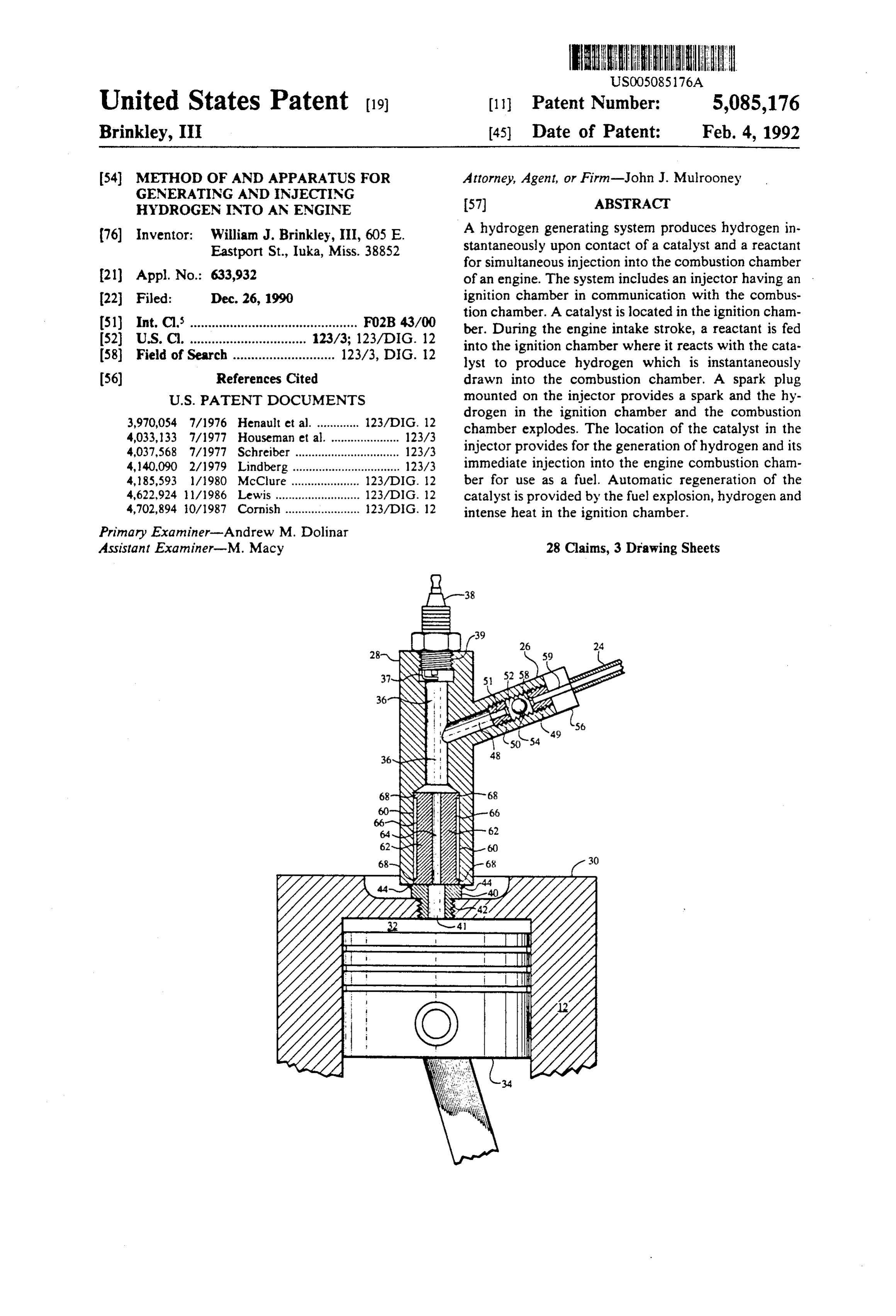
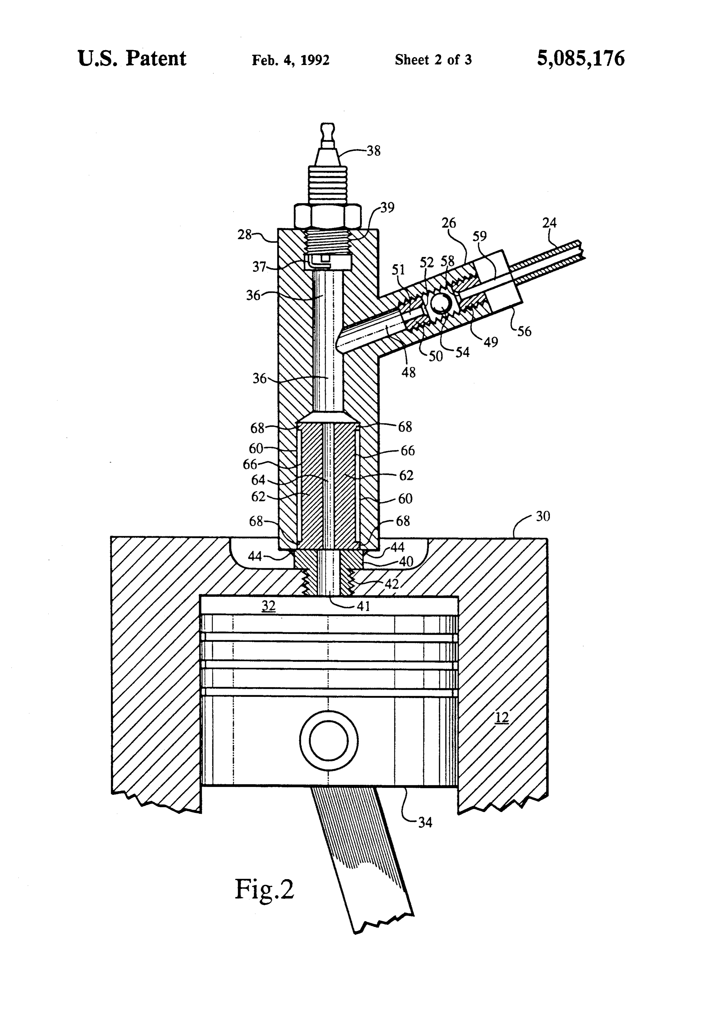
mediately available and ready for use without further connected to the hydrogen manifold 22 for the purpose ducting or handling as a fuel for an engine. of checking pressures and temperatures in manifold 22. Experiments indicate that the catalyst located in the Referring to FIG. 2, the details of the construction of injector housing is maintained in a permanent active one of the hydrogen generator-injector units 28 is illus state, i.e., it does not require a separate process or treat- 5 trated, along with the connection of the unit to the ment to reactivate the catalyst because of a build up of cylinder head 30 associated with one of the combustion oxidation thereon. It is believed that the catalyst in the chambers 32 which contains a conventional reciprocat injector housing actually does experience deactivation ing piston 34. The conventional inlet and exhaust valves by the build up of oxidation thereon, but that the cata on the engine 10 are not shown. lyst is automatically reactivated by the removal of such 10 The injector housing 28 is formed of a solid piece of oxidation during each four cycle process of the engine metal with a cylindrical bore therethrough which forms by the intense heat and explosion and hydrogen to an ignition chamber 36 extending the length of the hous which the injector catalyst is exposed during the power ing. A spark plug 38 is screwed into the upper end of the cycle. In any event, by practice of the invention, the injector housing 28, which is threaded at 39, so that the injector catalyst is not subject to any long term deacti- 15 spark plug tip 37 communicates with the ignition cham vation which noticeably impairs its hydrogen generat ber 36. The lower end of injector 28 has a threaded base ing capacity. 40 which is sized to screw into the standard, threaded A source of the reactant, which may be a manifold spark plug inlet 42 of the cylinder head 30. The hydrogen generating unit which operates on a water or threaded injector base 40 is welded to the main injector steam on catalyst principle, supplies hydrogen and 20 housing 28 as indicated at 44 to provide an airtight fit steam, or steam, or water, or moist air through a steel and prevent the escape of gases.
ball check valve into the injector housing. The main injector housing 28 has a reactant inlet port In general, the catalyst of the system is metallic and 26 for the introduction of the reactant at an elevated comprises metals which are known to be useful togen temperature into ignition chamber 36. FIGS. 1 and 2 erate hydrogen instanteously upon contact with a reac- 25 show the inlet ports 26 to be connected through hydro tant. The catalyst is selected from the group consisting gen manifold 22 to a reactant source comprising a mani of iron, nickel, iron-nickel, copper, silver, platinum, fold hydrogen generation unit (FIG. 3) as hereinafter palladium, molybdenum and manganese. described. However, it will be apparent that any suit The exhaust product of the use of hydrogen as a fuel able source of a reactant could be used. will be hydrogen and oxygen and water vapor, which 30 The inlet port 26 has a central bore 48 therethrough may be recycled and further used as the source of the which is threaded at 49. A threaded steel hydrogen jet reactant which is fed into the injector. 50 is screwed into inlet bore 48. The threaded hydrogen Moreover, the injector body may be constructed of a jet 50 has a bore 51 therein which communicates with catalyst material whereby the inside surface of the injec the inlet bore 48, and a ball check 52. The design of ball tor ignition chamber throughout the length of the injec- 35 check 52 and a steel ball 54 is such that the flow of tor body itself functions as a catalyst for the generation reactant through inlet port 26 into inlet bore 48 and of hydrogen gas for fuel. ignition chamber 36 is permitted when the steel ball 54 BRIEF DESCRIPTION OF THE DRAWINGS is seated on ball check 52. A brass inlet fitting 56 having a seat 58 for the ball 54 is screwed into the threaded inlet
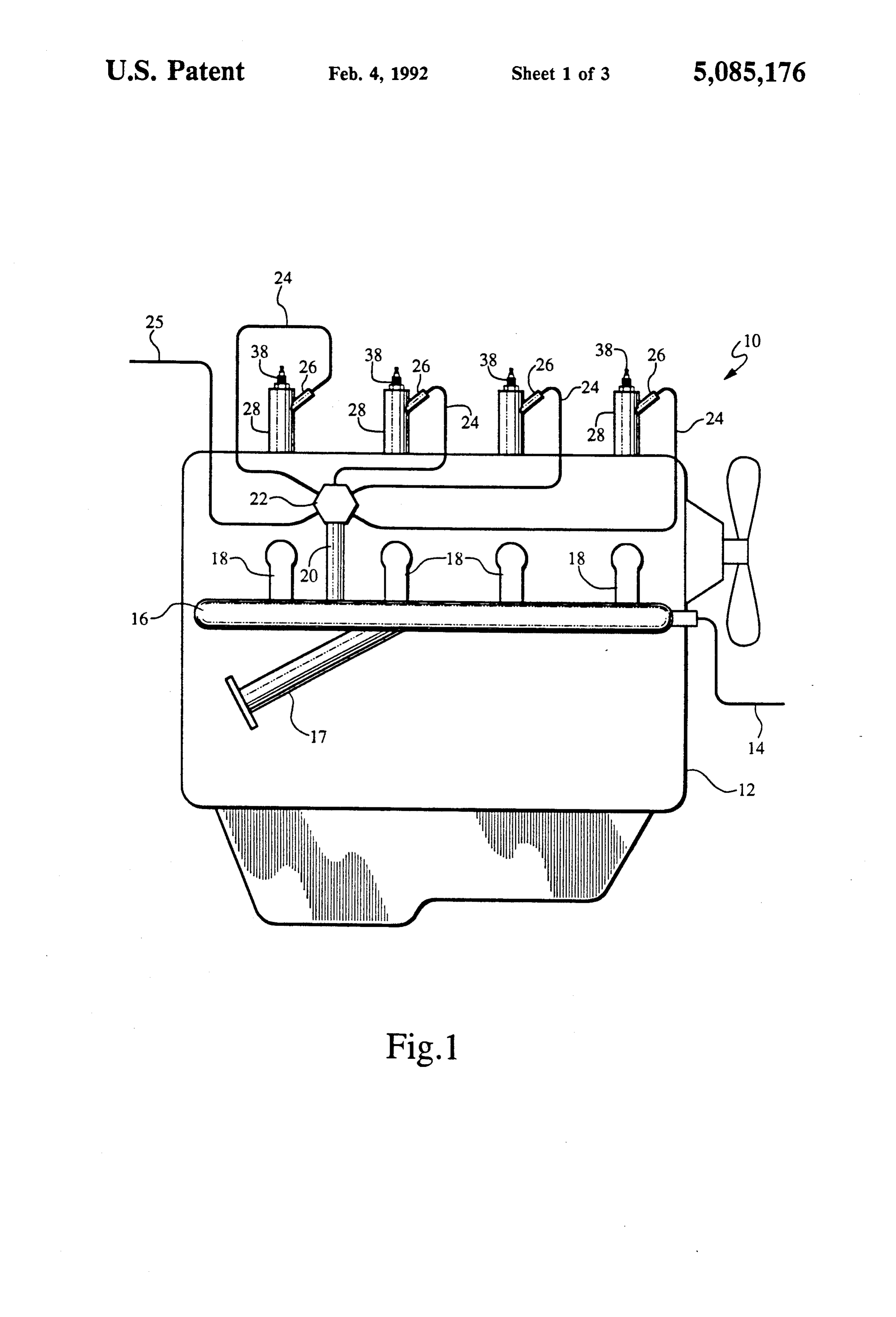
FIG. 1 is a side elevational view of an internal com- 40 bore 48. The brass inlet fitting 56 has a longitudinal bore bustion engine with the hydrogen generator-injector 59 therethrough which permits for the passage of reac apparatus of the present invention mounted thereon. tant from the supply lines 24 to inlet bore 48. When the FIG. 2 is a front elevational view, partially broken ball 54 is seated against seat 58, as hereinafter described, away, showing the hydrogen generator-injector an airtight seal is provided between the ball 54 and the mounted on the cylinder head of the engine. 45. seat 58.
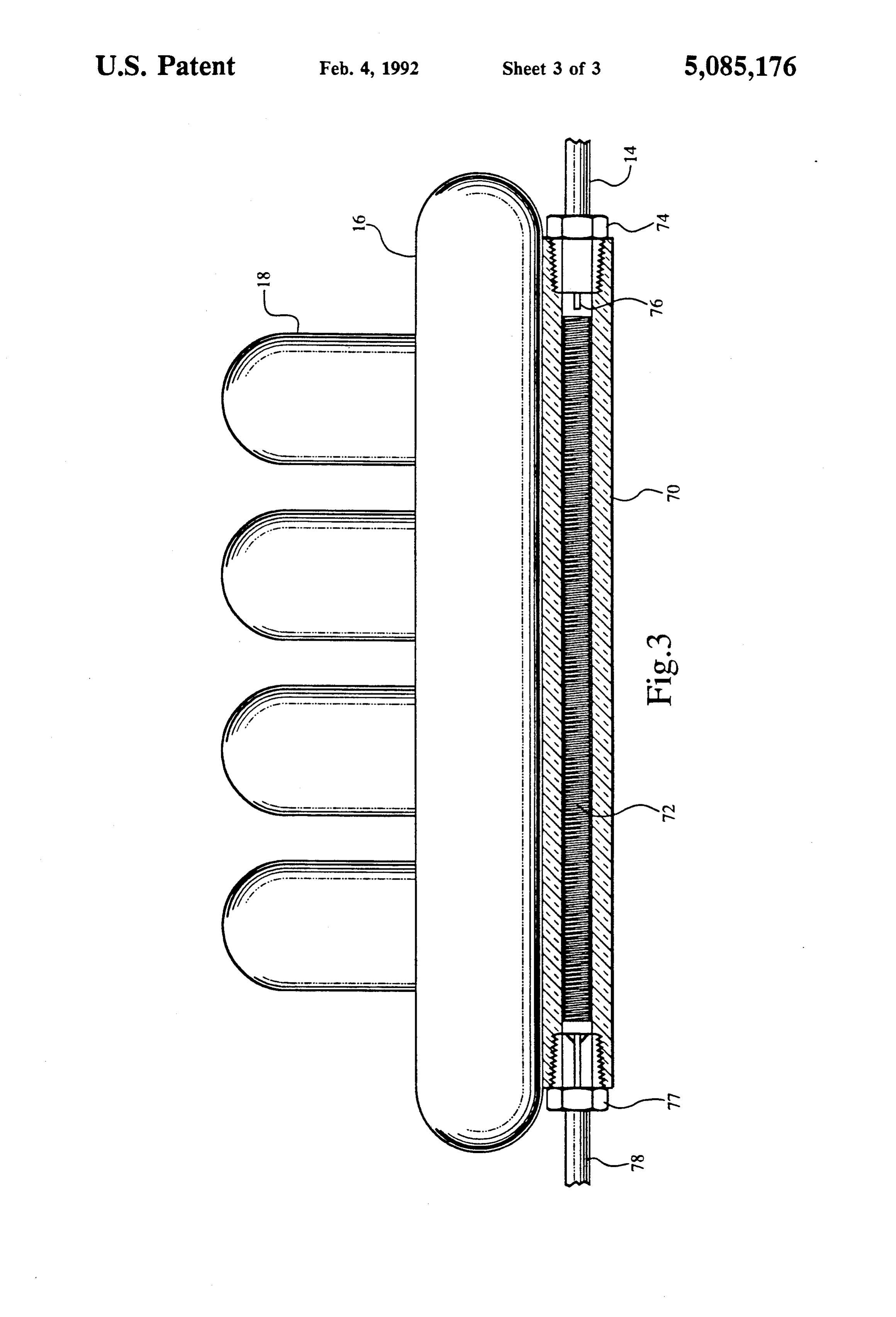
FIG. 3 is a front elevational view, partially broken Extending upwardly from the lower end of the injec away, showing a manifold mounted auxiliary hydrogen tor housing 28 is a cylindrical, longitudinal bore 60 generating unit for use in conjunction with the hydro which is concentric with the bore 36 which defines the gen generator-injector unit of the present invention to ignition chamber. A catalyst 62 in the form of a cylindri provide a source of reactant of steam and/or hydrogen 50 cal piece of metal is positioned in the bore 60 and itself and steam. has a central bore 64 which is concentric to and aligned DESCRIPTION OF THE PREFERRED with the bore 36 which forms the ignition chamber and EMBODIMENT the bore 41 which passes through the threaded injector base 40. The catalyst 62 is sized to have a circumference
Referring to the drawings, in FIG. 1, there is shown 55 slightly less than the circumference of the bore 60 a preferred embodiment of the invention in association whereby an insulating air gap 66 and insulating means with a conventional, four cylinder internal combustion 68, which may be small projections at either end of the engine indicated generally at 10. The engine has a water catalyst 62 or a continuous insulation ring, contacts the cooled engine block 12, and a cast iron exhaust manifold walls of bore 60 and maintains the catalyst 62 in spaced 16 having an exhaust pipe 17 and exhaust headers 18, all 60 apart relation to the adjacent sides of ignition chamber as well known and usually found on a convention four 36.
cylinder internal combustion engine. A water inlet 14 is In a preferred embodiment of the hydrogen genera connected to manifold 16 as hereinafter described. tor-injector, the main injector housing 28 is formed of An upwardly projecting manifold stem 20 extends solid piece of cold-rolled steel having dimensions of from the manifold 16 to a hydrogen manifold 22, from 65 approximately 5 inches long and an O.D. of of an inch. which a plurality of hydrogen supply lines 24 extend to The longitudinal bore 36 which forms the injector igni the hydrogen and steam injector inlets 26 of each of the tion chamber is drilled on center to a 5/16 inch diame hydrogen generator-injector units 28. Another line 25 is ter. The bore 48 through inlet port 26 is a inch diame
Page 7
ter. The insulating air gap 66 which surrounds the cata in the super heated range whereby hydrogen will be lyst 62 is 1/16 inch. The longitudinal movement of the generated by the contact of the injected reactant with ball 54 is between 1/6 inch and 3/32 of an inch. The the catalyst 62 and housing 28, and instantly drawn into catalyst 62 is formed of a solid, cylindrical piece of the combustion chamber 32 during the intake stroke. cold-rolled steel having a length of approximately 1 and 5 During the compression stroke, when the pressure in 3/8 inches, an O.D. of 5/8 inch and I.D. of 3/6 inch. the combustion chamber 32 and ignition chamber 36 The injector housing 28 and the catalyst 62 are made which communicates therewith builds up, the ball 54 from the same material. Alternatively, the injection will be pressed tightly against the seat 58 to prevent the chamber and the catalyst may be made of the same escape of any gases out of inlet port 26. At the proper material. O time, the spark plug 38 provides an igniting spark which Referring to FIG. 3, there is illustrated one possible initiates the explosion and subsequent expansion stroke. . embodiment of the source of the reactant which is sup The ignition chamber 36 along with the combustion plied to the injector 28 through inlet port 26. A mani chamber 32, including the catalyst 62, is subjected to the fold hydrogen generator unit comprising a catalyst explosion. Based on observations and experiments, it is chamber 70 is mounted in heat transfer relationship to 15 believed that the catalyst 62 does not retain any observ the cast iron exhaust manifold 16 by mounting means able residual deactivation following the normal four which are well known and not illustrated. Alterna stroke cycle of the engine, because experimental units tively, particularly in engines which have a longitudinal have been operated without the loss of efficiency and bore in the exhaust manifold, the catalyst chamber 70 generating capacity of the catalyst as is normally found may be formed inside of the exhaust manifold 16. The 20 in a catalyst which is part an oxidation process for the catalyst chamber 70 houses an auxiliary catalyst 72 generation of hydrogen. It is believed that the effect of which is formed of a threaded rod which is sized for a the intense temperatures and explosion, and possibly tight slip fit throughout catalyst chamber 70. The pur hydrogen, in the ignition chamber 36 and combustion pose of the screw thread on the auxiliary catalyst 72 is chamber 32, to which the catalyst 62 is exposed, func to increase the surface area of the catalyst for the steam 25 tions to deoxidize or reduce, any oxidation build up on to contact as it proceeds through catalyst chamber 70. the catalyst 62 which would manifest itself by a loss of As is well known, increasing the surface area of contact efficiency and decrease in hydrogen generating capac between the steam and the catalyst increases the hydro ity. The operating temperature of the catalyst 62 is in gen generation. A source of water, which may be pre the range of about 850 F. to about 1600 F. As the heated, is fed to water inlet 14, passes through water 30 hydrogen is ignited and burned it produces an extraor inlet fittings 74 and to water jet 76 from which the dinary quantity of heat which is immediately available water emerges in the form of a fine, misty spray. The to heat the catalyst 62 and injector 28 to the superheated water passes along the heated catalyst chamber 70 temperatures at which the reactant-on-catalyst process where it is heated to make steam which contacts the for the generation of hydrogen works most efficiently. auxiliary catalyst 72 to generate hydrogen through a 35 Operation of the hydrogen generator-injector 28 causes reduction process well known to those skilled in the art. the catalyst 62 and combustion chamber 32 to become A mixture of hydrogen gas and steam passes through progressively heated which provides the heat needed to outlet fittings 77 to a hydrogen and steam outlet 78. In cause both the dissociation of water and steam to hydro the embodiment shown in FIG. 3, the hydrogen and gen and oxygen and the generation of hydrogen by steam passing through outlet 78 is ducted to the mani oxidation of the catalyst 62. Thus, the heat generated fold 22 from which it passes to the injectors 28 via during operation causes the generator-injector 28 to hydrogen lines 24. become highly efficient in operation. In an engine with an exhaust manifold having a longi An auxiliary heating source or liquid or gaseous fuels tudinal bore therein which is useful for the catalyst including hydrogen, gasoline, diesel, or alcohol may be chamber 70, the hydrogen and steam generated in the 45 used to start and bring the apparatus and its components catalyst chamber 70 may be removed via a manifold up to the operating temperatures in the range of from stem 20 as shown in FIG. 1. Of course, the hydrogen about 850 F. to about 1600 F.
and steam or other reactant which is fed into the injec What is claimed is:
tor 28 may be provided by other sources of reactants as 1. A method of generating and injecting hydrogen is well known to those skilled in the art. 50 into the combustion chamber of an engine comprising: In the illustrated, preferred embodiment of the inven providing an ignition chamber in communication tion, the catalyst is formed of a piece of solid, cold with the combustion chamber of an engine; rolled steel having the disclosed dimensions. The injec placing a catalyst in said ignition chamber; tor housing 28 also is formed of a piece of solid, cold heating said catalyst;
rolled steel having the dimensions disclosed. However, 55 feeding a reactant into said ignition chamber for reac it is contemplated that other known catalysts will be tion with said catalyst to generate hydrogen in said used in this new and improved method of and apparatus ignition chamber;
for generating hydrogen for use as fuel in engines. The drawing a portion of said hydrogen from said ignition catalyst will be selected from the group consisting of chamber into said combustion chamber; iron, iron-nickel, nickel, copper, silver, palladium, plati- 60 igniting said hydrogen to cause an explosion and num, molybdenun and manganese. burning of said hydrogen in said ignition chamber In the operation of the invention, the reactant gener and said combustion chamber; and ated by a suitable source is fed to the inlet port 26 during exposing said catalyst to said hydrogen explosion. the intake-injection stroke whereby the ball 54 will be 2. The method according to claim 1 wherein said seated on ball check 52 to allow the reactant to pass reactant is selected from the group consisting of steam, through bore 51 and inlet bore 48 into the ignition hydrogen and steam, water and moist air. chamber 36. The temperature of the catalyst 62 and the 3. The method according to claim 1 wherein hydro injector housing 28 surrounding the catalyst 62 will be gen is generated in said ignition chamber by reaction of
Page 8
said reactant with said catalyst and by dissociation of a spark plug mounted at one end of said bore to pro said reactant caused by heat. duce a spark in said ignition chamber; 4. The method according to claim 1 wherein said a catalyst mounted in said ignition chamber; catalyst is selected from the group consisting of iron, an inlet port on said housing for feeding a reactant iron-nickel, nickel, copper, silver, palladium, platinun, into said ignition chamber for contact with said molybdenum and manganese. catalyst to generate hydrogen; 5. The method according to claim 1 wherein said means attached to the other end of said bore for con catalyst is heated to a temperature of about 850' F. to necting said housing to the combustion chamber of about 1600 F. for the generation of hydrogen. an engine whereby said ignition chamber commu 6. The method according to claim 1 wherein said 10 nicates with said combustion chamber. reactant fed into said ignition chamber is elevated to a 17. The hydrogen generator-injector according to temperature of about 850' F. to about 1600' F. for the claim 16 further comprising:
generation of hydrogen. means for heating said catalyst. 7. The method according to claim 1 wherein the 15 18. The hydrogen generator-injector according to engine is selected from the group consisting of the pis claim 16 wherein said catalyst is selected from the ton driven internal combustion engine, the rotary group dium, consisting of iron, nickel, copper, silver, palla platinum, molybdenum and manganese.
driven internal combustion engine, the gas turbine and 19. The hydrogen generator-injector according to the stirling engine.
8. The method according to claim 1 further compris 20 claim 16 wherein said engine is selected from the group ing the step of consisting of the piston driven internal combustion en gine, heating the ignition chamber to a temperature of bine, and the rotary driven combustion engine, the gas tur about 850 F. to about 1600" F. for the generation the stirling engine.
of hydrogen. 20. The hydrogen generator-injector according to 9. Apparatus for generating and injecting hydrogen 25 claim 16 further comprising:
a ball valve positioned in said inlet port whereby into the combustion chamber of an engine comprising: reactant is permitted to pass through said inlet port an injector having an ignition chamber in communi and into said ignition chamber during the intake cation with the combustion chamber of an engine: cycle of said engine and gas pressure within said a catalyst mounted in said ignition chamber; ignition chamber and said compression chamber means for heating said catalyst; 30 during the compression and explosion cycles of a source of reactant connected to said ignition cham said engine causes said ball valve to close to pre ber wherein said catalyst reacts with said reactant vent passage of fluids and gases through said inlet entering said ignition chamber to generate hydro port.
gen; and 21. The hydrogen generator-injector according to a spark plug for producing a spark in said ignition 35 claim 16 wherein said reactant is injected into said igni chamber to cause explosion and burning of said tion chamber during the intake cycle of said engine and hydrogen in said ignition chamber and said com a portion of said hydrogen generated by reaction of said bustion chamber. reactant and said catalyst is simultaneously drawn into 10. The apparatus according to of claim 9 wherein said combustion chamber.
said reactant is selected from the group consisting of 40 22. The method according to claim 1 wherein said steam, hydrogen and steam, water and moist air. injector chamber and said catalyst are made from the 11. The apparatus according to claim 9 wherein the same material.
hydrogen is generated by the reaction of said reactant 23. The apparatus according to claim 9 wherein said with said catalyst and by the dissociation of said reac injector and said catalyst are made from the same mate tant caused by heat. 45 rial.
12. The apparatus according to claim 9 wherein said 24. The hydrogen generator-injector according to reactant is introduced into said ignition chamber during claim 16 said housing and said catalyst are made from the intake stroke of said engine and a portion of the the same material.
hydrogen generated by reaction of said catalyst and said 25. The method according to claim 1 wherein said reactant is drawn into said combustion chamber. 50 reactant is supplied by a manifold hydrogen generator 13. The apparatus according to claim 9 wherein said unit operatively associated with the exhaust manifold of catalyst is heated to a temperature of about 850 F. to said engine.
about 1600" F. for the generation of hydrogen. 26. The apparatus according to claim 9 wherein said 14. The apparatus according to claim 9 wherein said source of reactant is a manifold hydrogen generator unit catalyst is selected from the group consisting of iron, 55 operatively associated with the exhaust manifold of said iron-nickel, nickel, copper, silver, palladium, platinum, engine.
molybdenum and manganese. 27. The hydrogen generator-injector according to 15. The apparatus according to claim 9 wherein the claim 16 wherein the reactant fed to said inlet port is engine is selected from the group consisting of the pis supplied by a manifold hydrogen generator unit opera ton driven internal combustion engine, the rotary tively associated with the exhaust manifold of said en driven internal combustion engine, and gas turbine, and gine.
the stirling engine. 28. The hydrogen generator-injector according to 16. A hydrogen generator-injector for use with an claim 16 wherein said reactant is selected from the engine having a combustion chamber comprising: group consisting of steam, hydrogen and steam, water a housing having a central bore therethrough forming 65 and moist air.
an ignition chamber;
Provenance
- Collection
- Cited prior art
- Original PDF
- patentimages.storage.googleapis.com →
- Filed
- 1990-12-26
- Pages
- 8
- Method
- pdftotext (the PDF's own text layer) + pdftoppm 300dpi page scans
- Source
- Google Patents bibliographic record
- Granted
- 1992-02-04
- Inventors
- William J. Brinkley, III
- Transcribed from
- patentimages.storage.googleapis.com →