patent · US5228529
Method for renewing fuel cells using magnesium anodes
20 July 1993
Page 1 — bibliographic record
United States Patent (19) 11) Patent Number: 5,228,529
Rosner (45) Date of Patent: Jul. 20, 1993 (54) METHOD FOR RENEWING FUEL CELLS Primary Examiner-Richard M. Camby USING MAGNESIUMANODES Attorney, Agent, or Firm-Weingram & Zall 76) Inventor: Stuart Rosner, 285 Stegman Pkwy.,
Jersey City, N.J.0305 57 ABSTRACT 1 Appl. :4. 809,303 Renewable fuel cells that produce hydrogen gas, on 21 pp No 9 demand, are used to power a vehicle. When the usable 22 Filed: Dec. 17, 1991 volume of hydrogen gas produced by the fuel cells is 51) int. Cli................................................ B60K 1/00 depleted, the magnesium anode is converted into mag 52 U.S. C. ................................... 180/653; 180/165; nesium hydroxide precipitate. The magnesium hydrox 429/49; 423/657 ide precipitate is removed and collected for recycling 58) Field of Search .................... 180/65.1, 65.2, 65.3, and the magnesium anode and salt water electrolyte is 180/165; 429/27, 29, 49; 423/657; 60/39.02, replaced, thus easily and conveniently re-energizing the 39.12 fuel cell. The magnesium hydroxide precipitate is recy (56) References Cited cled to recapture the magnesium which is then formed into new magnesium anodes. The primary power source
3,830,662 8/1974 Kinsey .................................. 429/49 waste product produced by the operation of the fuel 4,413,040 1 1/1983 Carr ....... ... 429/49 cell is non-polluting water.
4,841,731 6/1989 Tindell ....... . . 60/39.2 4,950,561 8/1990 Niksa et al. ........ ... 429/27 5,135,817 8/1992 Shimogori et al. ................. 423/657 8 Claims, 4 Drawing Sheets
ELECTRICAL VEHICLE
ELECTRICAL POWER CONTROL POWER ELECTRIC
ELECTRICAL
MAGNESUM MAGNESIUM
ANODE
MAGNESUM
HYDROXDE MAGNESUM HYDROGEN
WASHER SLURRY
HYDROCHLORC
ACD
GAS w L-----e DRYER AND ESSE4
BRINE
CONCENTRATED MAGNESIUM
SOLAR CHORIDE
ENERGY EVAPORATOR GRANULES
ELEC
HEAT HEA ELECTRICA POWER LERTIC
EXCHANGER RANSFER
BOER
GENERATOR
Page 2
Drawing sheet — no readable text.
Page 3
Drawing sheet — no readable text.
Page 4
Drawing sheet — no readable text.
Page 5
Drawing sheet — no readable text.
Page 6
coupling magnesium with an active inert metal in saline
METHOD FOR RENEWING FUEL CELLS USING Water.
MAGNESIUM ANODES U.S. Pat. No. 3,542,598, to White, et al., discloses a sea water battery with an electrolyte recirculation cir
BACKGROUND OF THE INVENTION 5 cuit which requires no auxiliary energy source for oper 1. Field of the Invention ation. This invention also maximizes the utilization of The present invention relates to a method for using a the plates during operation of the battery.
plurality of renewable fuel cells (hydrogen gas genera vanic hydrogen Pat. No. 3,892,653, to Pacheco discloses a gal tors) to propel a vehicle, and re-energizing these fuel 10 trode generator that uses a magnesium elec in a salt cells by replacing their depleted anodes with new an both by electrochemical water solution to produce hydrogen gas odes manufactured from materials recovered and recy Hydrogen gas is producedreaction when and by electrolysis.
an electrical load is cled from the depleted fuel cells. This method incorpo connected between the electrodes. The resulting cur rates the use of solar energy to provide the primary rent flow is produced by an electrochemical reaction in recycling energy requirements and also to provide a 15 which a magnesium electrode is decomposed to pro non-polluting, economic method of recycling. duce hydrogen gas. This current flow also decomposes 2. Description of the Prior Art water contained in the electrolytic solution to produce The present invention comprises a process wherein hydrogen gas.
certain conventional apparatus or known process steps U.S. Pat. No. 3,943,719 to Terry et al. discloses a are used in a unique combination to achieve the objec 20 power system comprising a reactor in which a hydride tives of this invention. The prior art neither teaches nor absorbs hydrogen at low pressure and low temperature, suggests the methods, i.e. combination of steps, of the and then heating the hydride at constant volume so as to present invention. release large quantities of hydrogen at high tempera Prior art which may be relevant to a particular pro tures and pressure. This released hydrogen is used to cess of this invention is described hereinafter. 25 produce power and yield refrigeration. Electrical U.S. Pat. No. 2,925,455, to Eldensohn, discloses a power can be generated by expanding the released hy continuous-feed two-stage primary battery system. In drogen through a turbine or other power producing the first stage, an electrochemical reaction of an active devices.
metal with water continuously generates electrical en U.S. Pat. No. 4,055,962 to Terry discloses a hydro ergy and simultaneously generates a gas used as a reac 30 gen-hydride absorption system comprising a sequential tant in a second stage to produce additional electrical method of reversibly combining hydrogen with a hy energy. dride-forming material, heating the hydride at constant U.S. Pat. No. 3,036,141, to Goldenberg, discloses a volume, and means for conveying hydrogen between magnesium galvanic cell comprising a magnesium or the reactors. In the power or heat pump cycle, the magnesium alloy anode, an aqueous electrolyte, and an 35 hydride in a first reactor is heated to desorb hydrogen inert cathode. gas. The gas flows to a second hydride bed in a second U.S. Pat. No. 3,036,142, to Goldenberg, discloses an the reactor where it is absorbed at a temperature lower then improved magnesium galvanic cell in which magnesium temperature of desorption of the first hydride bed. Absorption reacts with water to produce magnesium hydroxide, leases the heat of the hydrogen by the second reactor re hydrogen gas and electricity. of absorption. This heat of absorption is U.S. Pat. No. 3,043,898, to Miller, et al., discloses a typically removed by a heat exchanger. In the heat gas depolarized battery comprised of a number of gase pump mode of operation, the above cycle is sequentially ous depolarized, metal primary cells cemented together repeated through a series of reactors so that the heat of in a series and provided with tension means to compress 45 absorption fluid.
is sequentially added to the heat exchange the cells as the metallic anodes are consumed. This compression maintains the distance between the elec areInoperated conjunction with the above, a plurality of reactors in a refrigeration mode of operation and in trode surfaces constant and thus maintains a constant voltage output. such a manner that the reactors of the heat pump cycle U.S. Pat. No. 3,218,195, to Corren, discloses methods are in a phase compatible with an opposing reactor of and apparatus for producing electricity intermittently 50 theU.S. refrigeration system.
Pat. No. 4,090,361 to Terry et al., discloses im upon demand, or continuously in a galvanic cell by a proved-power cycles for using the hydride-dehydride chemical reaction effected at the electrodes. hydrogen (HDH) power cycle to produce hydrogen U.S. Pat. No. 3,238,070, to Porter II, discloses a sec gas continuously at high pressure and elevated tempera ondary battery comprising a circulating electrolyte and 55 tures. This gas can be used to produce power and refrig a plurality of individual cells arranged to form this eration. The hydrogen gas can be passed directly to an battery. The cells are formed of a zinc-oxygen electro expansion device, such as a turbine, or the hydrogen gas chemical couple. can be the working fluid used to transfer heat to a sec U.S. Pat. No. 3,247,042, to Tamminen, discloses a ondary system. Terry discloses using the HDH cycle to galvanic battery capable of delivering large currents continuously produce hydrogen gas to drive an expan without appreciable voltage declines for prolonged sion device such as a turbine.
periods. This patent teaches that circulation of the elec K. K. Kelley, Energy Requirements And Equilibria trolyte increases the use of a depolarizing substance and And The Dehydration, Hydrolysis And Decomposition reduces the internal resistance of the battery and thus Of Magnesium Chloride, Technical Paper 676, U.S. decreases the inherent voltage drop during discharge. 65 Department of the Interior, 1945, discloses the dehydra U.S. Pat. No. 3,256,504, to Fidelman, discloses the tion reaction and hydrolysis of magnesium chloride. production of hydrogen by reacting magnesium with Magnesium and Magnesium Alloys, The Interna water, the reaction being accomplished by galvanically tional Magnesium Association, Kirk-Othmer Encyclope
Page 7
dia of Chemical Technology, Volume 14, discloses vari Another object of the present invention is to provide ous commercial processes for producing magnesium. a stored energy source that can be easily and economi The Chemical Process Industries, 2nd Edition, cally renewed.
Shreve, 1956 pp. 223-227, 319-323, discloses various Still another object of the present invention is to commercial methods for producing magnesium. provide a high degree of recycling of the materials and Warming Trend, Cook, Forbes, Feb. 20, 1989, pp. chemicals involved in the process. 68-69 discloses solar energy system applications. A further object of the invention is to provide an , . . . The Optics of Non-Imaging Concentrators, energy source for vehicles that is competitive in terms Light and Solar Energy, Welford et al. (1978), discloses of range and speed with conventional motor vehicles. solar energy concentration applications, considerations 10 A still further object of the present invention is to and power yields. convert solar energy into the heat and electrical power Sun Master Corporation sales brochure, solar-ther needed to supply the major energy needs for the re mal energy collector, discloses a commercial solar con newal process.
centrator based upon a compound parabolic concentra 15 Another object of the present invention is to avoid tor reflector. atmospheric pollution resulting from the combustion Small Community Experiment #1, Ossage City, products of a gasoline powered engine.
Kans, Barber, Proceedings of the Distributed Receiver The objects of the foregoing invention are achieved Solar Thermal Technology Conference, Apr. by a plurality of fuel cells (hydrogen gas generators), 24-25(1985) pp. 13-20, discloses the experience gained 20 containing a magnesium anode wherein these fuel cells from a one hundred KW electric solar plant using a are installed in a vehicle. The fuel cells generate hydro solar concentrator. gen gas by galvanic reaction which is controlled by Automobiles, New Age EVs, Shuldiner, Popular varying the electrical load, i.e., the resistance, con Mechanics, September 1991, pp. 27-29, discloses possi nected to the fuel cells. A short circuit (zero resistance) ble oil savings and environmental considerations in 25 load provides maximum production of hydrogen gas using all electric or hybrid electric vehicles. within these fuel cells.
Battery Chargers, Allen. Popular Mechanics, Sep The hydrogen gas produced by the fuel cells (hydro tember 1991 (pp. 30-31, 102), discloses the use of elec gen gas generators) is vented and collected in a burner tric batteries to propel vehicles. mechanism. In one embodiment, the hydrogen gas is Unique Mobility, Inc., Sales Brochure (1990) dis 30 mixed in an appropriate ratio with oxygen from the closes commercially available electric propulsion sys atmosphere and then ignited. The heatenergy produced tems with range extenders. by burning the hydrogen gas is used to increase the V 160 Stirling Engine Program Update, Johansson et temperature of atmospheric air. This hot air drives a al., SAE Technical Paper Series 880542, International turbine/generator set to produce electrical power. The Congress and Exposition, Feb. 29-Mar. 4, 1988, dis 35 electrical power from the turbine/generator set is closes the progress made in developing a vehicular stored in storage batteries and/or applied directly to the engine that can operate from a multitude of different electric motors that the vehicle.
fuels -liquid, gaseous, or solid. In another embodiment, the hydrogen gas is used to Kaylor-Kit Electric R 100 MPG Hybrid Car Sales fuel a Sterling engine. This engine can drive an electri Brochure (1990), discloses a gas-electric replacement in cal generator to produce electrical power that is stored unit for an original VW power plant. storage batteries and/or applied directly to the elec EV Engineering Guidebook: Electric Vehicle Con tric motors that propel the vehicles.
version for the 1980's, Shipps, 3E Vehicles, pp. 21-25, mechanically still another embodiment, the Sterling engine can 49-52, 1981, discloses advantages, methods and prob 45 conventional combustion propel the vehicle in a manner similar to a lems of converting a vehicle to an electric motor pro engine. Burning the hydrogen pelled vehicle and/or to a hybrid vehicle that uses both ing water as an emission product. gas also produces non-pollut electric motors and a combustion engine to propel the As hydrogen gas is generated through galvanic ac vehicle.
tion of the fuel cell, a magnesium anode is depleted and
SUMMARY OF THE INVENTION 50 magnesium hydroxide precipitate is formed. Eventually A principal object of the present invention is to pro fuel no usable volume of hydrogen gas is generated by the cell.
vide a non-polluting energy source for vehicles. When the volume of hydrogen gas generated reaches Another object of the present invention is to provide or approaches this critical "out-of-gas' level, the opera an energy source that can be renewed from solar en 55 tor drives the hydrogen powered vehicle into a service ergy.
Still another object of the present invention is to station to have the fuel cells renewed or replaced. Re newal comprises removing the depleted magnesium provide an affordable, cost efficient, power source for anode, removing or filtering the old electrolyte solution vehicles. and removing the magnesium hydroxide precipitate and A further object of the present invention is to provide 60 then re-energizing (renewing) the fuel cell (hydrogen an alternative energy source to energy derived from oil gas generator) by filling it with fresh electrolytic solu products. tion (or the filtered electrolytic solution plus water) and A still further object of the present invention is to installing a new magnesium anode. The magnesium convert solar energy into a form that is easily storable, hydroxide precipitate is collected for recycling into transportable, and self contained. w 65 new magnesium anodes as described hereinafter. An additional object of the present invention is to The magnesium hydroxide precipitate is dried. This provide an environmentally benign power source that dried precipitate is then washed to remove water-solu does not require elaborate controls or safeguards. ble impurities. After washing, the washed magnesium
Page 8
hydroxide precipitate is drained but only to the point reactors are cooled so that this exothermic reaction where a slurry of magnesium hydroxide is formed. does not raise the hydride material above its equilibrium This magnesium hydroxide slurry is combined with temperature. Production of the hydride continues under hydrochloric acid in a reactor to produce magnesium controlled temperature until the equilibrium state is chloride. Due to the water content from the slurry, the reached in which the hydride is saturated with hydro magnesium chloride is in the form of a magnesium chlo gen at substantially the pressure at which the hydrogen ride brine. This brine is filtered to remove solid impuri gas was introduced into the reactor and at the equilib ties and then dried in a heated evaporator or spray rium temperature for the particular hydride. dried. Drying the magnesium chloride brine produces After charging, the reactor system is sealed. magnesium chloride granules. O The charged, sealed reactors are heated by circulat These magnesium chloride granules are then loaded ing a heated into a plurality of sealable electrolytic cells and heated dium throughtransfer a heat fluid or other heat exchange me exchange coil on each reactor. The to a molten state. Electrical power is then applied to passage of the heated transfer fluid these electrolytic cells to cause the magnesium chloride heat exchange coils increases the through the reactor temperature in the to disassociate into magnesium and hot chlorine gas. 5 reactor to substantially above the activation tempera The magnesium is formed by conventional manufac turing methods into new magnesium anodes to be used ture. Due to the release of hydrogen gas from the hy dride, the pressure of the hydrogen gas in the reactor to renew depleted fuel cells. increases substantially. This phenomena of chemical The chlorine gas is recycled into hydrochloric acid as compression of the hydrogen gas occurs during activa follows. The chlorine gas is mixed with hydrogen gas in 20 tion as a result of the constant volume imposed by the a burner or combustion chamber and then ignited. The closed reactor system.
resulting reaction produces hydrochloric gas which is The compressed hydrogen gas is passed via conven then bubbled through water to produce hydrochloric tional manifold means to an expansion device such as a acid. This acid is recycled by reacting it with the mag turbine nesium hydroxide slurry, previously mentioned, so as to 25 hydrogenofgas a turbine/generator set. The compressed expands and drives the turbine. This ex produce the magnesium chloride brine. pansion reduces the pressure of the hydrogen gas and The aforementioned process requires significant amounts of energy particularly in the electrolysis of the concurrently, reduces its temperature. molten magnesium chloride and in drying the magne The lower pressure and temperature hydrogen gas is sium chloride brine. This energy is ideally and economi 30 recirculated to a reactor to be reabsorbed by the hydrid cally obtained from solar energy as described below. ing material and to recommence the HDH cycle. Solar energy is collected by a solar concentrator and Pressurized hydrogen continues to be released from used to increase the temperature of a heat transfer fluid the hydride material at a substantially constant pressure circulated past the area of solar concentration. This while the heat transfer fluid is circulated through the heated transfer fluid is circulated through the aforemen 35 reactor and until substantially all of the hydrogen is tioned evaporator so as to dry the magnesium chloride chemically disassociated from the hydride and released brine. In addition, in one embodiment, this heated trans as hydrogen gas.
fer fluid is circulated through a water-filled boiler After dehydriding is complete, the temperature of the where the heat transferred converts the water into reactor is decreased or allowed to decrease to below the steam. This steam drives a turbine/generator which, in hydride equilibrium temperature. The reactor is now turn, produces the electrical power for the electrolysis prepared to receive "cold' hydrogen gas such as from of the molten magnesium chloride in the electrolytic the turbine and recommence the HDH cycle. cells. By using a plurality of reactors, pressurized hydrogen In another embodiment, a turbine/generator set is gas can be discharged from one or more reactors while driven by hydrogen gas produced by a hydride-dehy 45 other reactors are recharging. This method renders a dride-hydrogen (HDH) cycle. In this embodiment, a substantially continuous supply of pressurized hydro plurality of closed and interconnected reactor vessels gen to drive a turbine.
contain a solid material capable of reacting with hydro By using a HDH system to generate electrical power gen gas at relatively low temperature and pressure to from solar energy, the solar energy is more efficiently form hydride compounds. Typically, a plurality of dif 50 converted to electrical power than when the solar en ferent hydride materials may be used when HDH sys ergy is used to produce steam to drive a turbine/genera tems are operated in a phase compatible with an oppos tor. In addition, HDH systems can be developed to ing reactor in a heat pump/refrigeration cycle. The provide 24 hour production of power based upon solar equilibrium pressure of the hydrogen gas generated and energy. In this embodiment, a plurality of reactors the temperatures of absorption and desorption will de 55 could be interconnected to sequentially provide pres pend upon the specific hydriding characteristics of the surized hydrogen gas to drive a turbine/generator hydridable material used and the heat sources available while concurrently the waste heat produced by the for supplying heat to bring the hydride to the equilib recharge (refrigeration) cycle or from other processes, rium temperature and then activating the hydride so as such as the heat generated by the magnesium hydroxide to release hydrogen gas. with hydrochloric acid reaction, etc., could be recircu Assume that initially the hydridable material is in a lated to the hydrogen deabsorbing (heat pump) reactors cold, deactivated state. Here "cold' means a tempera wherein this waste heat would maintain these reactors ture lower than the temperature required for hydriding; above their activation temperatures. generally ambient temperature or lower. Hydrogen gas In an alternative embodiment, a portion of the solar is charged into the system at a relatively low pressure 65 energy captured each day could be stored in a heat and temperature. This hydrogen gas combines chemi reservoir and then withdrawn after the sun sets so as to cally with the hydridable material in the reactor in an enable extended, nighttime, or 24 hour operation of heat exothermic reaction. Typically, during charging, the and power generation.
Page 9
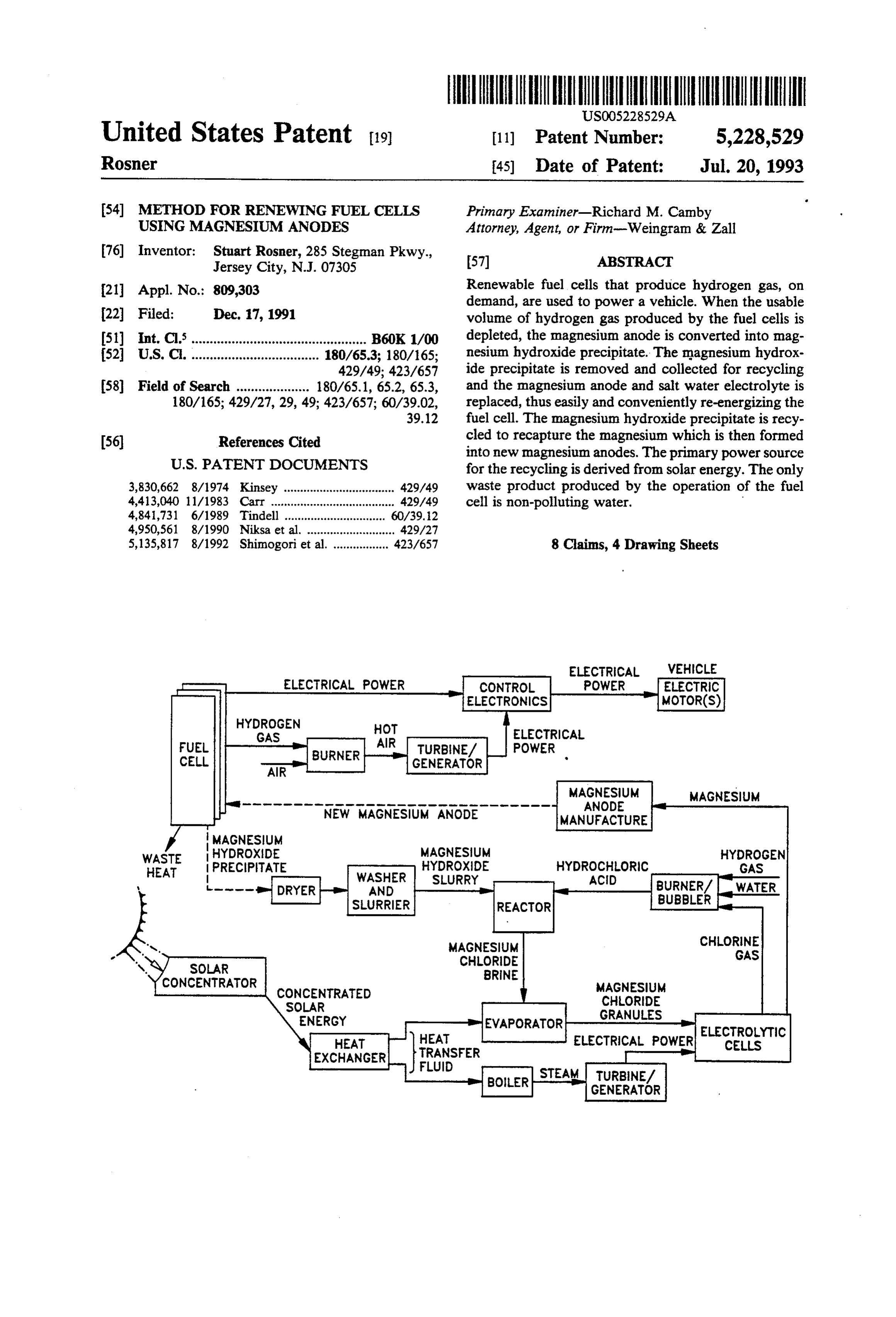
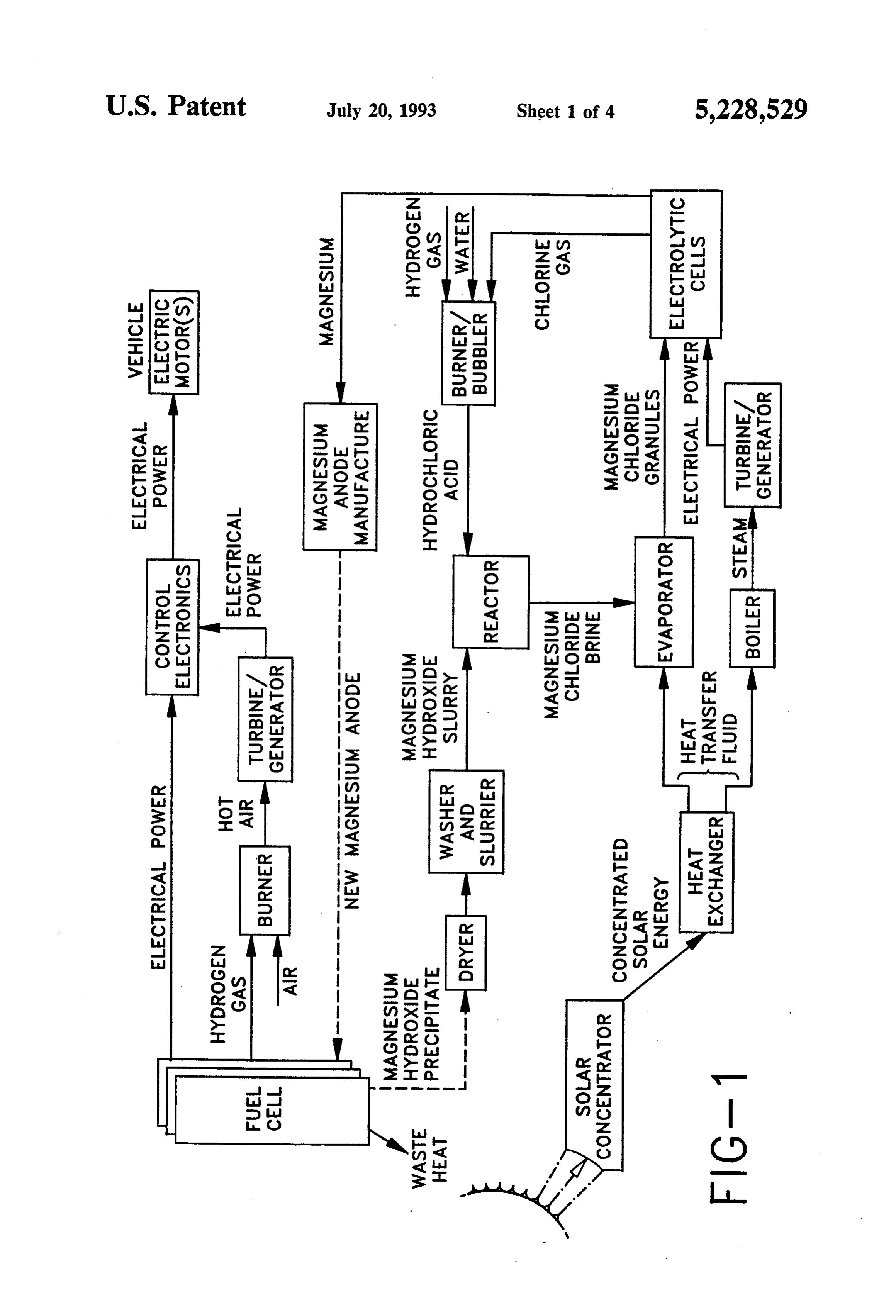
The process of combining magnesium hydroxide FIG. 1 is a diagram illustrating the functional interac slurry with hydrochloric acid to produce magnesium tion of the apparatus involved in generating hydrogen chloride and then obtaining magnesium by the electrol gas from fuel cells and then recycling and renewing the ysis of magnesium chloride is modeled on the Dow magnesium anode of these fuel cells. chemical seawater extraction process for obtaining FIG. 2 is a process diagram illustrating the steps magnesium, Magnesium and Magnesium Alloys, Kirk involved in generating hydrogen gas from fuel cells and Othmer Encyclopedia of Chemical Technology, V 14. using this hydrogen gas to produce electricity via a P.577-578, incorporated herein by reference. An alter turbine/generator to propel an electric vehicle until the native method is the Norsk Hydro process, Magnesium fuel cells no longer produce a usable volume of hydro and Magnesium Alloys, Kirk-Othmer Encyclopedia of 10 gen gas.
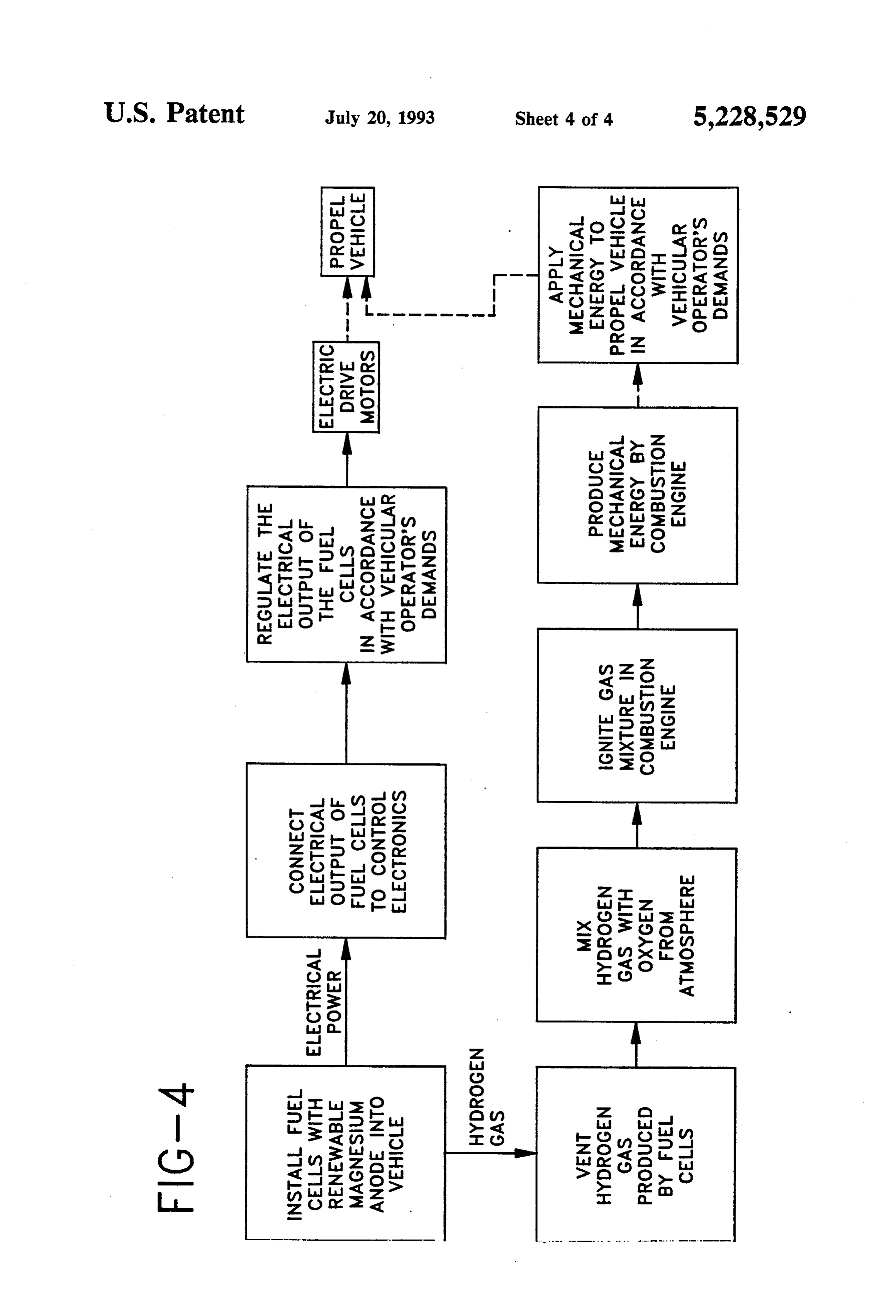
Chemical Technology, V 14, p. 578-580, incorporated FIG. 3 is a process diagram illustrating the steps herein by reference, wherein the magnesium hydroxide involved in generating hydrogen gas from fuel cells and is calcined to magnesium oxide, mixed with carbon and using this hydrogen gas to operate a Sterling engine that magnesium chloride, and formed into pellets. These mechanically propels a vehicle.
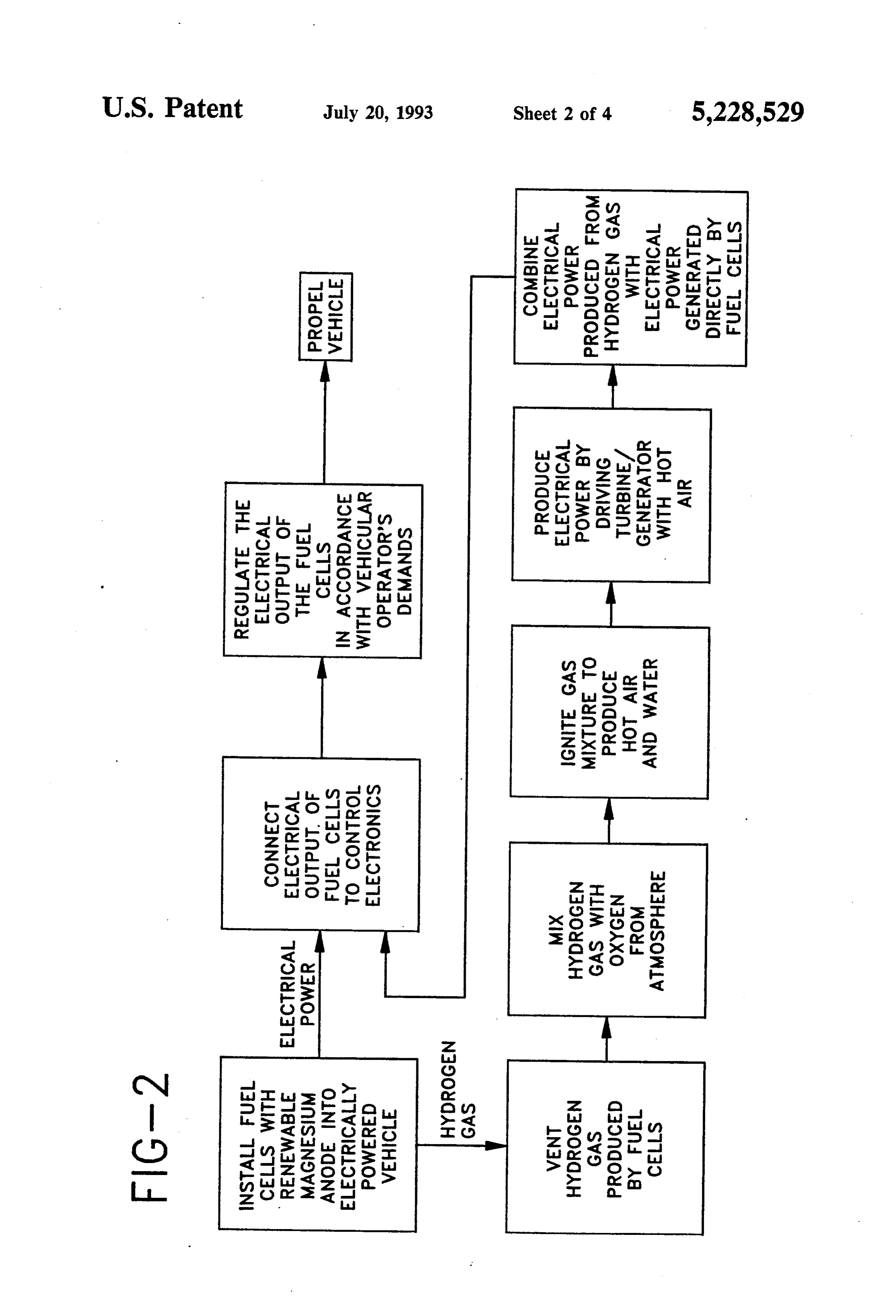
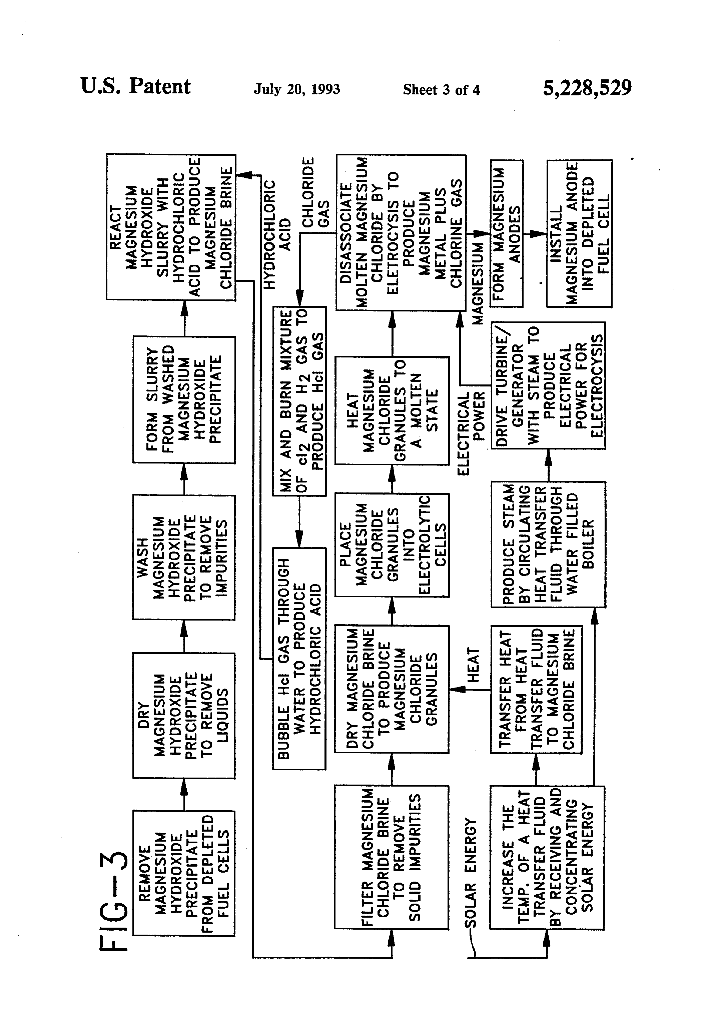
pellets are dried and fed into the top of an electrically 15 FIG. 4 is a process diagram illustrating the sequence heated furnace. Chlorine gas is pumped into the bottom of steps required to recycle magnesium hydroxide pre of the furnace. The reactions involved are: cipitate from depleted fuel cells (hydrogen gas genera tors) into new magnesium anodes.
20 DETAILED DESCRIPTION
The method of this invention defines a two stage
These exothermic reactions, once started, basically sus process whereby in the first stage, magnesium anode tain themselves. Molten magnesium chloride is fed into fuel cells (hydrogen generators) are depleted by power electrolytic cells where magnesium and chlorine gas are 25 ing an electric vehicle. In another embodiment, the produce by electrolysis. hydrogen gas generated by these fuel cells fuel a com Another alternative method is based on the Natural bustion engine, such as a Sterling Engine, which me Lead Industries brine process for obtaining magnesium, chanically propels a vehicle. An alternative to this em Magnesium and Magnesium Alloys, Kirk-Othmer Ency bodiment, is to drive a generator from the combustion clopedia of Chemical Technology, V 14, p. 580-581, in 30 engine. This generator then provides the electrical corporated herein by reference. Applying this process, power to propel the vehicle. In the second stage, the the magnesium hydroxide is concentrated into a brine fuel cells are re-energized (renewed) by removing the and treated with calcium chloride to obtain magnesium depleted materials, i.e., the magnesium hydroxide pre chloride brine. This brine is further concentrated and cipitate, depleted magnesium anode and electrolyte, then spray dried. Spray drying the brine produces a dry 35 recycling the magnesium hydroxide precipitate to pro magnesium chloride powder which is heated to a mol duce new magnesium anodes, and then installing these ten state and fed to an electrolytic cell. Magnesium and new (or renewed) magnesium anodes and fresh or fil chlorine gas are then produced by electrolysis of the tered electrolyte in the fuel cell. molten magnesium chloride.
Still another alternative method is based on the First Stage-Depleting The Fuel Cell (Hydrogen American Magnesium brine process for obtaining mag Generator), FIG. 2 nesium, Magnesium and Magnesium Alloys, Kirk Step 1-Install Fuel Cells With Renewable Magnesium Othmer Encyclopedia of Chemical Technology, V 14, p. Anode Into A Vehicle 581-582, incorporated herein by reference. Applying this process, the magnesium hydroxide from the fuel 45 A plurality of fuel cells, the exact number being de cell is first treated with hydrochloric acid or calcium termined by the energy required to obtain the speed and carbide to obtain magnesium chloride brine. This brine range desired for a particular vehicle mass, is installed in is then concentrated, purified, and spray dried. The an accessible location in a vehicle. In the preferred resulting dry magnesium chloride powder is electro embodiment, a fuel cell (hydrogen generator) such as lyzed at greater than 150 kA in modified, diaphragmless described in U.S. Pat. No. 3,892,653 to Pacheco, incor (USSR type) cells. This method achieves better than porated herein by reference, is used. 80% current efficiency with a DC power consumption In this fuel cell, an active magnesium electrode and an of about 15.4 kw-hr per kg of magnesium produced. A inactive electrode is immersed in a salt-water electro vacuum ladle is used to remove the molten magnesium. lyte. The inactive electrode could be composed of stain The USSR diaphragmless-type electrolyte cells provide 55 less steel (which may be used as a container), carbon, or for simplified magnesium metal and chlorine gas collec other conductible material that is non-reactive. The fuel tion because their anode and cathode spaces form a cell is hermetically sealed except for a vent to a mani common working unit. fold to permit collecting the hydrogen gas. The volume Other processes for reclaiming magnesium from mag of hydrogen gas generated by this fuel cell varies in nesium hydroxide could be readily incorporated into accordance with the electrical resistance connected the process of this invention. between the electrodes. As this resistance is decreased, BRIEF DESCRIPTION OF THE DRAWINGS the current flow through the fuel cell increases as does the rate of hydrogen gas production. The volume of
These as well as further objects and advantages of the hydrogen gas generated is proportional to the current present invention will become apparent to those skilled 65 flow.
in the art from a review of the following detailed speci The electrochemical reaction decomposes the mag fication, reference being made to the accompanying nesium electrode by forming magnesium hydroxide drawings in which: which is deposited in the bottom of the fuel cell. When
Page 10
the magnesium electrode is consumed, the fuel cell passes through expansion and compression cycles and ceases to generate hydrogen gas. thus force the pistons to move. Concurrent with the electrochemical activity is elec The gas fuel heating system of the Sterling engine trolysis that liberates hydrogen gas and oxygen gas. No reflects the design of a common gas furnace. The air significant amount of oxygen gas passes out of the fuel cell because the oxygen gas becomes involved in the temperature of incoming air is increased to about 500 electrochemical reaction and also forms hydrogen per C. in a preheater. This preheated air flows into a com oxide. bustor through a gas venturi and a combustor swirler. This fuel cell (hydrogen generator) incorporates: (1) The air flow through the venturi is designed to induce the reaction of the active metal, magnesium, with water 10 a proportional flow of gaseous fuel, such as hydrogen, to produce hydrogen gas from water, (2) the differing in order to obtain the proper air-fuel mixture. A torch electrical potential of two metals to produce an electri ignitor ignites this air-fuel mixture. The hot gases pro cal current, and (3) the use of the electric current flow duced by combustion, heat and expand the helium ing through the fuel cell to produce hydrogen gas from water by electrolysis. The current producing reaction 15 working fluid in the sealed system. This working fluid is: then drives the pistons of the drive system. The airflow and air/fuel ratio are constantly adjusted by the air-fuel control system as it strives to maintain the helium working gas at a constant temperature. The
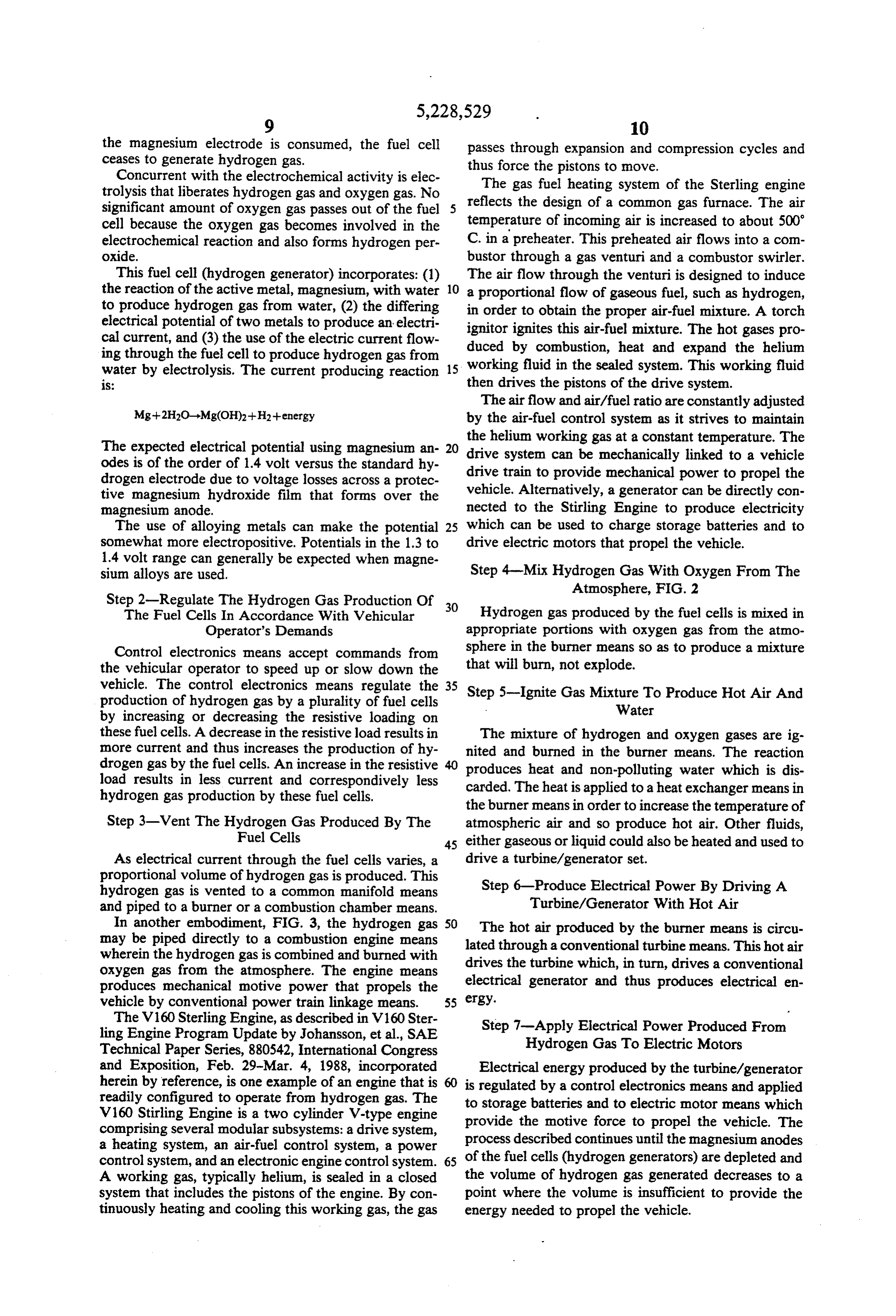
The expected electrical potential using magnesium an 20 drive system can be mechanically linked to a vehicle odes is of the order of 1.4 volt versus the standard hy drive train drogen electrode due to voltage losses across a protec to provide mechanical power to propel the tive magnesium hydroxide film that forms over the vehicle. Alternatively, a generator can be directly con magnesium anode. nected to the Stirling Engine to produce electricity The use of alloying metals can make the potential 25 which can be used to charge storage batteries and to somewhat more electropositive. Potentials in the 1.3 to drive electric motors that propel the vehicle. 1.4 volt range can generally be expected when magne sium alloys are used. Step 4-Mix Hydrogen Gas With Oxygen From The Atmosphere, FIG. 2
Step 2-Regulate The Hydrogen Gas Production Of 30
The Fuel Cells In Accordance With Vehicular Hydrogen gas produced by the fuel cells is mixed in Operator's Demands appropriate portions with oxygen gas from the atmo Control electronics means accept commands from sphere in the burner means so as to produce a mixture the vehicular operator to speed up or slow down the that will burn, not explode.
vehicle. The control electronics means regulate the 35 Step 5-Ignite Gas Mixture To Produce Hot Air And production of hydrogen gas by a plurality of fuel cells Water by increasing or decreasing the resistive loading on these fuel cells. A decrease in the resistive load results in The mixture of hydrogen and oxygen gases are ig more current and thus increases the production of hy nited and burned in the burner means. The reaction drogen gas by the fuel cells. An increase in the resistive produces heat and non-polluting water which is dis load results in less current and correspondively less carded. The heat is applied to a heat exchanger means in hydrogen gas production by these fuel cells. the burner means in order to increase the temperature of Step 3-Vent The Hydrogen Gas Produced By The atmospheric air and so produce hot air. Other fluids, Fuel Cells 45 either gaseous or liquid could also be heated and used to As electrical current through the fuel cells varies, a drive a turbine/generator set. proportional volume of hydrogen gas is produced. This hydrogen gas is vented to a common manifold means Step 6-Produce Electrical Power By Driving A and piped to a burner or a combustion chamber means. Turbine/Generator With Hot Air In another embodiment, FIG. 3, the hydrogen gas 50 The hot air produced by the burner means is circu may be piped directly to a combustion engine means lated through a conventional turbine means. This hot air wherein the hydrogen gas is combined and burned with drives the turbine which, in turn, drives a conventional oxygen gas from the atmosphere. The engine means produces mechanical motive power that propels the electrical generator and thus produces electrical en vehicle by conventional power train linkage means. 55 ergy.
The V160 Sterling Engine, as described in V160 Ster Step 7-Apply Electrical Power Produced From ling Engine Program Update by Johansson, et al., SAE
Technical Paper Series, 880542, International Congress Hydrogen Gas To Electric Motors and Exposition, Feb. 29-Mar. 4, 1988, incorporated Electrical energy produced by the turbine/generator herein by reference, is one example of an engine that is is regulated by a control electronics means and applied readily configured to operate from hydrogen gas. The to storage batteries and to electric motor means which V160 Stirling Engine is a two cylinder V-type engine provide the motive force to propel the vehicle. The comprising several modular subsystems: a drive system, a heating system, an air-fuel control system, a power process described continues until the magnesium anodes control system, and an electronic engine control system. 65 of the fuel cells (hydrogen generators) are depleted and A working gas, typically helium, is sealed in a closed the volume of hydrogen gas generated decreases to a system that includes the pistons of the engine. By con point where the volume is insufficient to provide the tinuously heating and cooling this working gas, the gas energy needed to propel the vehicle.
Page 11
Second Stage-Renewing The Magnesium Anodes To STEP 14-Dry Magnesium Chloride Brine To Produce Re-Energize The Fuel Cells (Hydrogen Generators), Magnesium Chloride Granules FIG. 4 The purified magnesium chloride brine is transported Step 8-Remove Magnesium Hydroxide Precipitate 5 to an evaporator means where the magnesium chloride From Depleted Fuel Cells brine is force dried by heat from solar energy means or The generation of hydrogen gas by the fuel cell is from other energy sources. As an alternative, the brine achieved by sacrificing the magnesium anode. As hy can be spray dried. The magnesium chloride brine is drogen gas is produced, the galvanic reaction depletes 10 placed in contact with heat exchanger means wherein solar heated fluid is circulated. The heat transferred the magnesium anode and forms magnesium hydroxide from the fluid to the magnesium chloride brine evapo precipitate. Once the portion of the magnesium anode in rates the water. The dry magnesium chloride is typi contact with the electrolytic solution is depleted, all cally in the form of 840-2,380 m (8-20 mesh) granules. hydrogen gas generation ceases.
Fuel cells (hydrogen generators) can be renewed and 15 STEP 15-Heat Magnesium Chloride Granules To the magnesium hydroxide recycled to form new magne Molten State sium anodes. This is achieved by opening the fuel cell in The dry magnesium chloride granules are typically a manner dictated by its design. For example, the entire placed in large holding tanks which are connected to top section with attached magnesium anodes can be and feed into a plurality of electrolytic cells. The gran unfastened and removed. Alternatively, the magnesium 20 ules could also be periodically loaded into electrolytic anodes could be designed to be unfastened and removed cells by manual or other automatic methods. through the top of the fuel cell. Other removal means In addition to the magnesium chloride, sodium chlo are readily available. ride and other salts are typically added to the electro Having removed the top or the magnesium anodes lytic cells to lower the melting point of the magnesium from the fuel cell, the magnesium hydroxide and elec 25 chloride and to increase its conductivity. trolytic bath can be removed, e.g., dumped out, poured As used in the DOW process, these electrolytic cells out, or filtered and collected for recycling. are large, rectangular, ceramic-lined pots with a capac Step 9-Dry Magnesium Hydroxide Precipitate To ity of about ten tons of molded magnesium chloride and Remove Liquids salt. The internal parts of a cell form the cathode. A 30 plurality of cylindrical graphite anodes are passed
The collected magnesium hydroxide precipitate is through a refractory top cover.
dried by any conventional drier means to remove the After the magnesium chloride granules and sodium liquid content. The dried material comprises a magne chloride are loaded into the electrolytic cells, the cells sium hydroxide precipitate, salt from the electrolytic 35 are sealed, and the magnesium chloride is heated to bath and impurities. about 710 C, which is sufficient to melt the magnesium chloride (melting point of 651 C). Heat is provided by
Step 10-Wash Magnesium Hydroxide Precipitate To external heating means such as electrical resistance Remove Impurities heating using electrical energy derived from solar en The dried magnesium hydroxide precipitate is 40 ergy means or from conventional furnace means. In washed by conventional washer means. The wash addition, rent heat is also generated by the electrolysis cur flowing through the molten magnesium chloride.
water dissolves the salt left from the electrolytic bath and removes this salt plus any other water soluble impu STEP 16-Disassociate Molten Magnesium Chloride rities. By Electrolysis To Produce Magnesium Plus Chlorine Gas
Step 11-Form Magnesium Hydroxide Slurry 45
After the magnesium hydroxide precipitate is generated An electrical current produced from electrical power washed, excess wash water is drained off until only a across the by solar energy means, or the like, is applied electrodes of the electrolytic cells. The mol slurry of magnesium hydroxide precipitate remains. ten magnesium chloride disassociates as follows: Step 12-React Magnesium Hydroxide Slurry With 50
Hydrochloric Acid To Produce Magnesium Chloride
Brine
The electrolytic cells operate at about six volts and a
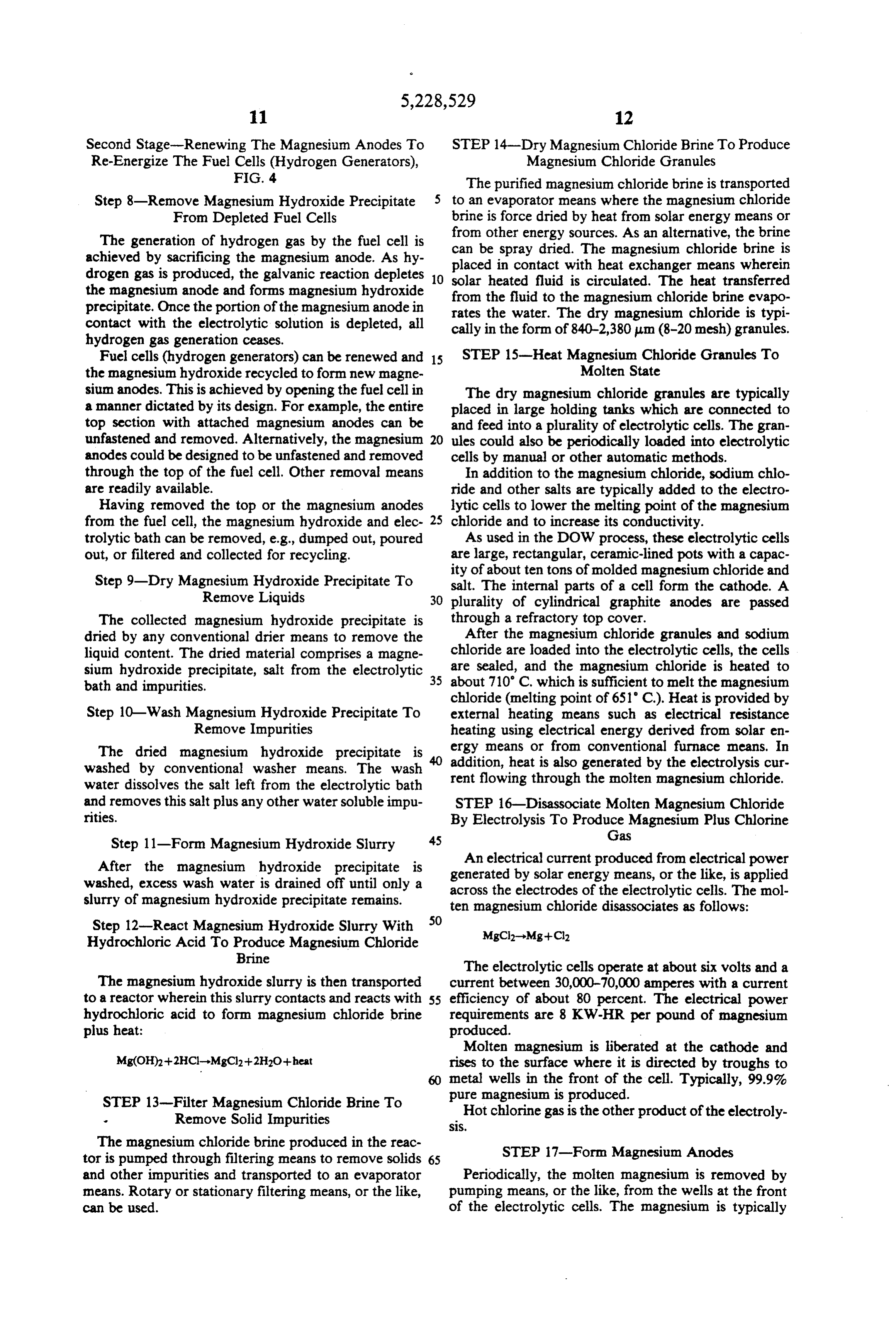
The magnesium hydroxide slurry is then transported current between 30,000-70,000 amperes with a current to a reactor wherein this slurry contacts and reacts with 55 efficiency of about 80 percent. The electrical power hydrochloric acid to form magnesium chloride brine requirements are 8 KW-HR per pound of magnesium plus heat: produced.
Molten magnesium is liberated at the cathode and rises to the surface where it is directed by troughs to metal wells in the front of the cell. Typically, 99.9% pure magnesium is produced.
STEP 13-Filter Magnesium Chloride Brine To Hot chlorine gas is the other product of the electroly
The magnesium chloride brine produced in the reac STEP 17-Form Magnesium Anodes tor is pumped through filtering means to remove solids 65 and other impurities and transported to an evaporator Periodically, the molten magnesium is removed by means. Rotary or stationary filtering means, or the like, pumping means, or the like, from the wells at the front can be used. of the electrolytic cells. The magnesium is typically
Page 12
pumped into a crucible car which is then transported to to track the sun while the larger, primary mirror is a casting factory means. The magnesium is emptied into fixed. The second stage concentrator receives the solar a holding furnace, alloying pots, or the like, and then energy reflected by the Fresnel mirror and then concen pumped or poured into molding means. These molding trates this solar energy onto a cylindrical absorber-pipe means form the magnesium into the shape required for through which a heat transfer fluid flows. Use of a the magnesium anodes used to renew a depleted fuel second stage concentrator can heat the heat transfer cell. fluid to the 200 to 600 F. range. STEP 18-Install Magnesium Anode Into Depleted STEP 22-Transfer Heat From Heat Transfer Fluid To Fuel Cell O Magnesium Chloride Brine
The magnesium anodes, as produced by the recycling The solar-heated transfer fluid is circulated through process or from newly mined magnesium, or the like, the evaporator means of Step 14 by conventional piping are installed in a plurality of depleted fuel cells along means. The heat energy derived from the transfer fluid with an appropriate volume of new or filtered electro dries the magnesium chloride brine to produce magne lytic solution. These renewed fuel cells are then sealed 15 sium chloride granules. The heat transfer fluid is contin and reinstalled in the vehicle. uously recycled between the solar concentrator and the STEP 19-Burn Mixture Of Chlorine And Hydrogen evaporator so that energy is constantly being trans Gas To Produce Hydrochloride Gas ferred from the solar concentrator to the evaporator. The chlorine gas produced by electrolysis in the elec 20 STEP 23-Drive Turbine/Generator To Produce trolytic cells is drawn into regenerative furnace means, Electrical Power For Electrolysis mixed with hydrogen gas, ignited and burned. The In one embodiment, the solar-heated transfer fluid is resulting product is hydrogen chloride gas. circulated through a water-filled boiler by conventional STEP 20-Bubble Hydrogen Chloride Gas Through 25 piping means. The high-temperature transfer fluid trans Water To Produce Hydrochloric Acid forms the water in the boiler into steam. The steam produced
The hot hydrogen chloride gas is transported by conventional by the solar-powered boiler is transferred by conventional means to a bubbler means wherein the piping means to a conventional turbine/- hydrogen chloridega is bubbled through water. The turn drives theThe generator set. steam drives the turbine which in generator.
hydrogen chloride dissolves and disassociates in water 30 In another embodiment, the solar-heated transfer to form hydrochloric acid which is recycled to the fluid is circulated through a hydride-dehydride-hydro reactor of Step 12 wherein it reacts with the magnesium gen (HDHD system. In this system, a plurality of sealed, hydroxide slurry and forms magnesium chloride brine.
but interconnected, vessels contain a hydride material
STEP 21-Increase The Temperature Of The Heat 35 charged with hydrogen. Circulating the heated transfer Transfer Fluid By Concentrating Solar Energy fluid through these vessels increases the hydride tem Solar energy is used to economically provide the perature above the activation temperature, thereby large amounts of heat and electrical energy required to releasing hydrogen gas. Since the hydrogen gas is re recycle magnesium hydroxide precipitate into magne leased into a constant volume vessel, hydrogen gas at an sium anodes. Other energy sources could also be used elevated pressure and temperature is obtained. This either as a primary energy source or as supplemental hydrogen gas is connected by conventional piping energy sources. means to a turbine wherein the hydrogen gas expands Solar concentrator means are used that can generate and drives the turbine which in turn drives a generator. temperatures greater than 212 F. in a heat transfer fluid The expanded hydrogen gas also concurrently cools. means. In a preferred embodiment, mirrors of a solar 45 This lower pressure, cooled hydrogen gas is recircu concentrator lock onto the sun as it rises and follows the lated to a reactor to be reabsorbed by the hydriding sun across the sky until it sets. These mirrors focus the material and to recommence the HDH cycle. By using energy from the sun onto a thin, black coated stainless a plurality of reactors, pressurized hydrogen gas can be steel pipe through which synthetic oil circulates. Typi discharged from one or more reactors while other reac cally, on a clear day, the solar energy collected heats SO tors are recharging. This method renders a substantially this oil to about 735 F. continuous supply of pressurized hydrogen to drive a In another embodiment, a compound parabolic cusp turbine.
reflector optically tracks the sun all day, all year long, The generator produces electrical power which is without any moving parts. The geometry of the cusp regulated and connected by conventional means to the reflector automatically concentrates the solar energy 55 electrolytic cells of Step 16. Thus, electrical power, onto an energy collector tube as long as the sun is produced from solar energy means, provides the electri within 70 from either side of the collector tube. Heat cal current needed to disassociate the magnesium chlo transfer fluid circulated through this collector tube can ride in the electrolytic cells. typically reach temperatures from 270 to 350 F. It will be understood that various changes in the In yet another embodiment, a compound parabolic details, materials, and arrangements of parts which have concentrator means can be used in conjunction with a been described and illustrated in order to explain the second stage non-imaging concentrator to attain a nature of the invention may be made by those skilled in higher concentration ratio and thus higher temperatures the art within the principle and scope of the invention as in the heat transfer fluid. Typically, the primary ele expressed in the appended claims.
ment is a lens or a mirror, such as a Fresnel lens whose 65 What I claim is:
facets are arranged in a circle. In an alternative modifi 1. A method of powering a vehicle with a plurality of cation, a linear Fresnel lens could be used. A second renewable magnesium anode fuel cells (hydrogen gas stage concentrator is then moved in a circular arc so as generators), comprising the steps:
Page 13
A. installing a plurality of renewable magnesium the magnesium hydroxide precipitate formed by anode fuel cells in a vehicle, galvanic action.
B. regulating the hydrogen gas production of the fuel 4. A method of powering a vehicle with a plurality of cells by control electronics means in accordance renewable fuel cells (hydrogen gas generators), the with vehicular operator's demands, 5 method comprising:
C. venting and collecting hydrogen gas produced by A. installing a plurality of renewable fuel cells in a the fuel cells, vehicle,
D. mixing the hydrogen gas with oxygen gas from the B. regulating the hydrogen gas production of the fuel atmosphere to produce a gas mixture, cells by control electronics means as commanded E. igniting and burning the gas mixture to produce 10 by the vehicular operator, hot air and a non-polluting waste product, water, C. venting the hydrogen gas produced by the fuel F. driving a turbine/generator means with the hot air cells to a hydrogen powered combustion engine, so as to produce electrical power, D. mixing the hydrogen gas with oxygen gas from the G. powering the vehicle with the hydrogen gas de atmosphere and igniting the gas mixture in the rived from the fuel cells until no further useful 15 combustion engine to produce mechanical energy, volume of hydrogen gas is produced, E. applying the mechanical energy to the motive H. renewing the depleted fuels cells by replacing the power means of the vehicle, and thus propelling magnesium anode, removing the magnesium hy the vehicle, droxide precipitate formed by galvanic action, and F. consuming hydrogen gas produced by the fuel replacing the electrolytic solution. 20 cells until the fuel cells are depleted, 2. A method of powering an electric vehicle with a G. removing the depleted magnesium anodes, magne plurality of renewable magnesium anode fuel cells (hy sium hydroxide precipitate and electrolytic solu drogen gas generators), comprising the steps: tion from the depleted fuel cells, A. installing a plurality of renewable magnesium H. renewing the depleted fuel cells by adding a vol anode fuel cells in an electric vehicle, 25 ume of fresh electrolytic solution and new magne B. regulating the hydrogen gas production of the fuel sium anodes.
cells by control electronics means in response to 5. A method of powering a vehicle with a plurality of commands of the vehicular operator, renewable magnesium anode fuel cells (hydrogen gas C. venting hydrogen gas produced by the fuel cells generators), comprising the steps:
by manifold means to a burner means, 30 A. installing a plurality of fuel cells with magnesium D. mixing the hydrogen gas with oxygen gas from the anodes in an electrically powered vehicle, atmosphere in the burner means to produce a gas B. regulating the hydrogen gas production of the fuel mixture, cells by control electronics means as demanded by E. igniting and burning the gas mixture to produce the operator, heat, 35 C. venting the hydrogen gas produced by the fuel F. increasing the temperature of atmospheric air by cells to a hydrogen powered combustion engine, this heat to produce hot air, D. mixing the hydrogen gas with oxygen gas from the G. circulating the hot air through a turbine/generator atmosphere and igniting the gas mixture in the means to produce electrical energy, combustion engine to produce mechanical energy, H. applying the electrical energy produced to storage 40 E. applying the mechanical energy to drive a genera battery means and to electric drive motor means, tor and thus produce electrical energy, I. consuming hydrogen gas derived from the fuel F. applying the electrical energy produced to storage cells until the fuel cells are depleted, battery means and to electric drive motor means, J. renewing the depleted fuel cells by adding a vol G. propelling the vehicle using the electrically pow ume of electrolytic solution and new magnesium 45 ered drive motor means, anodes. H. consuming hydrogen gas derived from the fuel 3. A method of powering a vehicle with a plurality of cells until the fuel cells are depleted, renewable magnesium anode fuel cells (hydrogen gas I. removing the depleted magnesium anodes, magne generators), comprising the steps: sium hydroxide precipitate and electrolytic solu A. installing a plurality of renewable fuel cells in a 50 tion from the depleted fuel cells, vehicle, J. renewing the depleted fuel cells by adding a vol B. regulating the hydrogen gas production of the fuel ume of fresh electrolytic solution and new magne cells by control electronics means as commanded sium anodes.
by an operator, 6. A method of powering a vehicle with a plurality of C. venting and collecting hydrogen gas produced by 55 renewable magnesium anode fuel cells (hydrogen gas the fuel cells, generators), comprising the steps: D. mixing the hydrogen gas with oxygen gas from the A. installing a plurality of renewable magnesium atmosphere and igniting this gas mixture in an en anode fuel cells in a vehicle, gine means, B. regulating the hydrogen gas production of the fuel E. producing mechanical energy by the engine cells by control electronics means in accordance means, with vehicular operator's demands, F. using the mechanical energy to provide motive C. burning the hydrogen gas to produce hot air and a power to propel the vehicle, non-polluting waste product, water, G. powering vehicle with the hydrogen gas derived D. driving a turbine/generator means with the hot air from the fuel cells until no further usable volume of 65 so as to produce electrical power, hydrogen gas is produced, E. powering the vehicle with the hydrogen gas de H. renewing the fuel cells by replacing the magne rived from the fuel cells until no further useful sium anode and electrolytic solution and removing volume of hydrogen gas is produced,
Page 14
F. renewing the depleted fuel cells by replacing the B. regulating the hydrogen gas production of the fuel magnesium anode, removing the magnesium hy cells by control electronics means in response to droxide precipitate formed by galvanic action, and commands of the vehicular operator, replacing the electrolytic solution. C. burning the hydrogen gas to produce heat, 7. A method of powering an electric vehicle with a D. increasing the temperature of atmospheric air by this heat to produce hot air, plurality of renewable magnesium anode fuel cells (hy E. circulating the hot air through a turbine/generator drogen gas generators), comprising the steps: means to produce electrical energy, A. installing a plurality of renewable magnesium F. applying the electrical energy produced to storage anode fuel cells in an electric vehicle, O battery means and to electric drive motor means, B. regulating the hydrogen gas production of the fuel G. consuming hydrogen gas derived from the fuel cells by control electronics means in response to cells until the fuel cells are depleted, commands of the vehicular operator, H. renewing the depleted fuel cells by adding a vol ume of electrolytic solution and new magnesium
C. burning the hydrogen gas to produce heat, 15 anodes, wherein the magnesium anode is produced D. increasing the temperature of atmospheric air by from a previously depleted magnesium anode by this heat to produce hot air, the steps of:
E. circulating the hot air through a turbine/generator A. removing a magnesium hydroxide precipitate means to produce electrical energy, from the fuel cell,
F. applying the electrical energy produced to storage 20 B. reacting the magnesium hydroxide precipitate battery means and to electric drive motor means, with hydrochloric acid to form magnesium chlo ride,
G. consuming hydrogen gas derived from the fuel C. heating the magnesium chloride to a molten cells until the fuel cells are depleted, state, so as to produce molten magnesium chlo H. renewing the depleted fuel cells by adding a vol 25 ride, ume of electrolytic solution and new magnesium D. disassociating the molten magnesium chloride anodes. by electrolysis to produce magnesium metal in a 8. A method of powering an electric vehicle with a highly pure form and chloride gas, plurality of renewable magnesium anode fuel cells (hy 30 E. forming the magnesium metal into fuel cell an drogen gas generators), comprising the steps: odes,
A. installing a plurality of renewable magnesium
F. installing these anodes in depleted fuel cells so as to re-energize the depleted fuel cells.
anode fuel cells in an electric vehicle, k
Provenance
- Collection
- Cited prior art
- Original PDF
- patentimages.storage.googleapis.com →
- Filed
- 1991-12-17
- Pages
- 14
- Method
- pdftotext (the PDF's own text layer) + pdftoppm 300dpi page scans
- Source
- Google Patents bibliographic record
- Granted
- 1993-07-20
- Inventors
- Stuart Rosner
- Transcribed from
- patentimages.storage.googleapis.com →