patent · US4828637
Method of applying painted carrier films to automobile body parts
9 May 1989
Page 1 — bibliographic record
United States Patent (19) 11 Patent Number: 4,828,637 Mentzer et al. (45) Date of Patent: May 9, 1989 54 METHOD OF APPLYING PAINTED (56) References Cited CARRIER FLMS TO AUTOMOBILE BODY U.S. PATENT DOCUMENTS
PARTS
75 Inventors: Charles C. Mentzer; Howard W. Cox, 3,654,012 4/1972 Schlager. both of Birmingham; William T. 3,827,130 8/1974 Baumann .
Short, Southfield, all of Mich. 4,052,241 10/1977 Walter .
73 Assignee: General Motors Corporation, Detroit, 4,548,843 10/1985 Kozuka et al. . Mich. 4,594,292 6/1986 Nagai et al. .
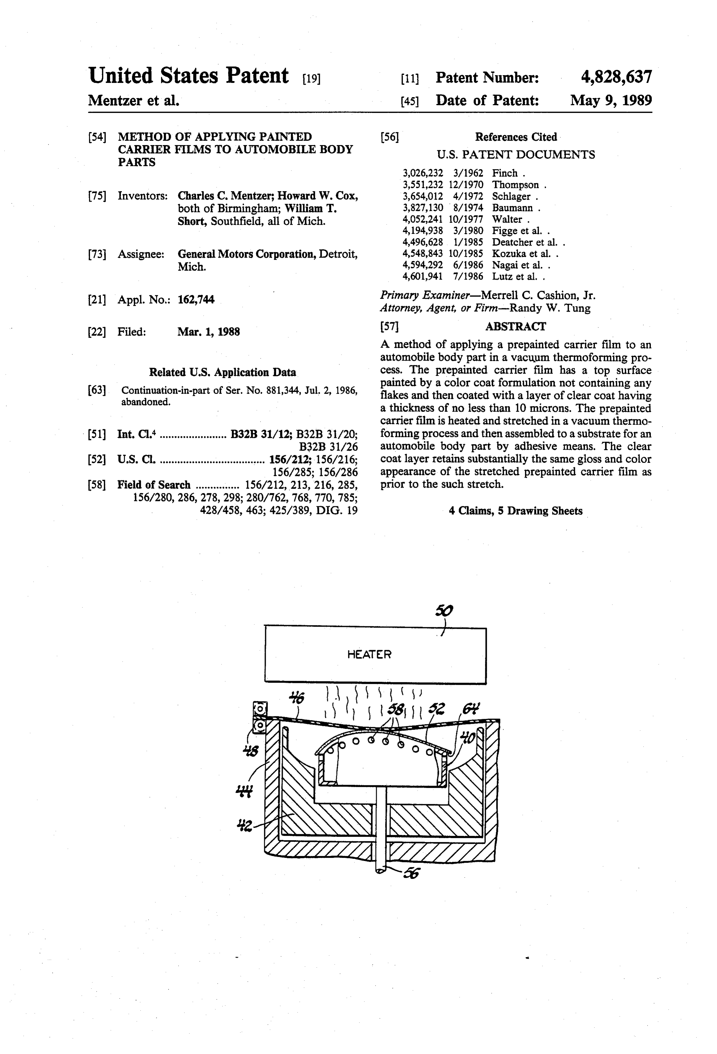
21 Appl. No.: 162,744 Primary Examiner-Merrell C. Cashion, Jr. Attorney, Agent, or Firm-Randy W. Tung 22 Filed: Mar. 1, 1988 57 ABSTRACT A method of applying a prepainted carrier film to an automobile body part in a vacuum thermoforming pro
Related U.S. Application Data cess. The prepainted carrier film has a top surface 63 Continuation-in-part of Ser. No. 881,344, Jul. 2, 1986, painted by a color coat formulation not containing any abandoned. flakes and then coated with a layer of clear coat having a thickness of no less than 10 microns. The prepainted carrier film is heated and stretched in a vacuum thermo 51) Int. Cl."....................... B32B 31/12; B32B 31/20; forming process and then assembled to a substrate for an B32B 31/26 automobile body part by adhesive means. The clear 52 U.S.C. .................................... 156/212;156/216; coat layer retains substantially the same gloss and color 156/285; 156/286 appearance of the stretched prepainted carrier film as 58 Field of Search ............... 156/212,213, 216, 285, prior to the such stretch.
428/458, 463; 425/389, DIG. 19 4 Claims, 5 Drawing Sheets
HEATER
Page 2
Drawing sheet — no readable text.
Page 3
Drawing sheet — no readable text.
Page 4
. NON-METALLIC BLACK
WITH CLEAR COAT
-- LIGHT-METALLIC SILVER
WITH CLEAR COAT
{x DARK-METALLIC RED
WITH CLEAR COAT
A NON-METALLIC BLACK ONLY
X LIGHT-METALLIC SILVER ONLY
V DARK-METALLIC RED ONLY
PERCENT STRAIN
FIG. 9
SO -- NON-METALLIC BLACK WITH 50 2O ME CRONS CLEAR COAT
3O NON-METALLIC BLACK ONLY
O 2O 4O 6O 80 1 OO 12O 140 16O 18O 200
PERCENT STRAN
FIG 1 O
Page 5
MEDIUM-METALLIC BLUE WITH CLEAR COAT
X 72 MICRONS
A S5 MICRONS
K> 42 MI CRONS
-- 27 MI CRONS
O S M CRONS
PERCENT STRAN
FIG 11
LIGHT-METALLIC SILVER WITH CLEAR COAT
A 250 MICRONS
X 9S ME CRONS
V 85 MICRONS
7O MICRONS
PERCENT STRAIN
Page 6
FAC ING SHEETS STRETCHEO AT 25% STRAIN
-- NON METALLIC BLACK
A DARK-METALLIC RED
& MEDIUM-METALLIC BLUE
GHT-METALLIC SILVER
CLEAR COAT THICKNESS, MICRONS
FIG 13 4O FACING SHEETS STRETCHED AT 100% STRAN
-- NON METALLIC BLACK
A DARK-METALLIC RED
O <> MEDIUM-METALLIC BLUE
O LIGHT-METALLIC SILVER
CLEAR COAT THICKNESS, MICRONS
Page 7
etc., severe stress cracking problems in the color coat
METHOD OF APPLYING PAINTED CARRIER layer were observed when these clear coats were FILMS To AUTOMOBILE BODY PARTS sprayed on a stressed color coat layer. We believe that the organic solvents contained in the clear coats initiate
This is a continuation-in-part of U.S. Ser. No. 5 crack growth in an already stressed color coat layer 881,344, filed July 2, 1986, which is being abandoned. which contains micro-cracks. This stress cracking in the FIELD OF THE INVENTION color coat layer can cause deterioration in the color The present invention generally relates to a method mobile part tois no appearance such an extent that the color of the auto of applying a painted carrier film to an automobile body 10 It is, therefore, longer acceptable. part and, more particularly, is concerned with a method assemble prepainted carrieroffilms an object the present invention to to automobile body of applying a painted carrier film to an automobile body parts in a vacuum thermoforming process. part by a thermoforming process in which our novel It is another object of the present invention to assem process enables the retainment of substantially the same color and gloss appearance after the painted carrier film 15 ble
prepainted carrier films to automobile body parts in vacuum thermoforming process in which even though has been stretched up to a strain of one hundred per
Cent. the films and the color coat layer on it are stretched, substantially the same gloss and color appearance are
BACKGROUND OF THE INVENTION retained after the stretch as prior to the stretch by the Automobile body parts are traditionally made of 20 use of a clear coat layer.
sheet metal or plastics painted with layers of pigmented It is a further object of the present invention to assem paints. The painting process of these parts requires elab ble prepainted carrier films to automobile body parts orate facilities and consequently large expenses. For such that all the body parts mounted on an automobile instance, a large floor space area must be maintained in are color matched within an acceptable color tolerance. a clean room environment for the spraying of paint and 25 SUMMARY OF THE INVENTION clear coat and for the baking and curing of such paint and clear coat on the body parts. Moreover, solvent In accordance with a preferred practice of our inven based paints are considered undesirable in recent years tion, a method of applying prepainted carrier films to because of environmental concerns. As a consequence, automobile body parts such that all the body parts have the evaporation of such solvents must be strictly con- 30 the same color appearance can be carried out by the trolled. It is, therefore, desirable to eliminate the paint following operative steps. First, a layer of a pigmented ing process completely in an automobile assembly plant paint is applied to a plastic film having sufficient thick by using prepainted carrier films. These prepainted ness in rigidity. A layer of a clear coat is then applied on carrier films may be applied to prefabricated vehicle top of the paint layer. The uncoated side of this plastic body parts in a vacuum thermoforming process. 35 film may then be optionally coated with a layer of adhe In the development of a vacuum thermoforming pro sive. We believe that instead of coating the film with cess to assemble a prepainted carrier film to a prefabri adhesive, a solid film of adhesive may also be used by cated vehicle body part, problems of various nature placing it in between the plastic film and the substrate were encountered. First, in a process where a two di for the body part. Such solid films of adhesive include mensional prepainted carrier film is assembled to a three 40 those in a web-like form. dimensional vehicle body part, it is inevitable that the The prepainted carrier film is heated in an oven to a carrier film must be stretched. The amount of stretch, or temperature at which the plastic film became suffi the total strain of the carrier film resulted from such ciently pliable such that it may be vacuum formed. The stretch varies from a few percent in the case of a flat temperature must body panel to as high as one hundred percent in a 45 adhesive layer on also the be sufficiently high such that the back of the prepainted film or the curved panel with sharp corners. We have found that separate adhesive film becomes for most automobile body part applications, the total painted film is then positioned tacky. over a This heated pre substrate for a strain is in the range between 10 to 50 percent. body part in a vacuum forming device. Vacuum is with When a carrier film covered with a color coat is stretched in the vacuum thermoforming process and 50 drawn from under the prepainted film such that the film assembled to a vehicle body part, the color and gloss wraps around and adheres to the substrate without appearance of the assembled part deteriorates signifi causing defects such as air bubbles. cantly from that of the original unstretched prepainted In our alternate embodiment, vacuum holes are carrier film. For instance, we have found that in the drilled into a supporting buck for the substrate in such a case of a metallic silver color basecoat, the 20' gloss 55 way that a heated film edge-wraps the substrate so that reading dropped from 87 for an unstretched carrier film the edges of the substrate are covered by prepainted to 25 for a carrier film stretched to 50% strain. It is film. After the excess film is trimmed off the substrate known by those skilled in the art of color matching that along the edges of the part, a completed automobile such a deterioration in gloss produces a part of unac body part with a painted surface is ready for assembly ceptable color appearance. 60 to an automobile.
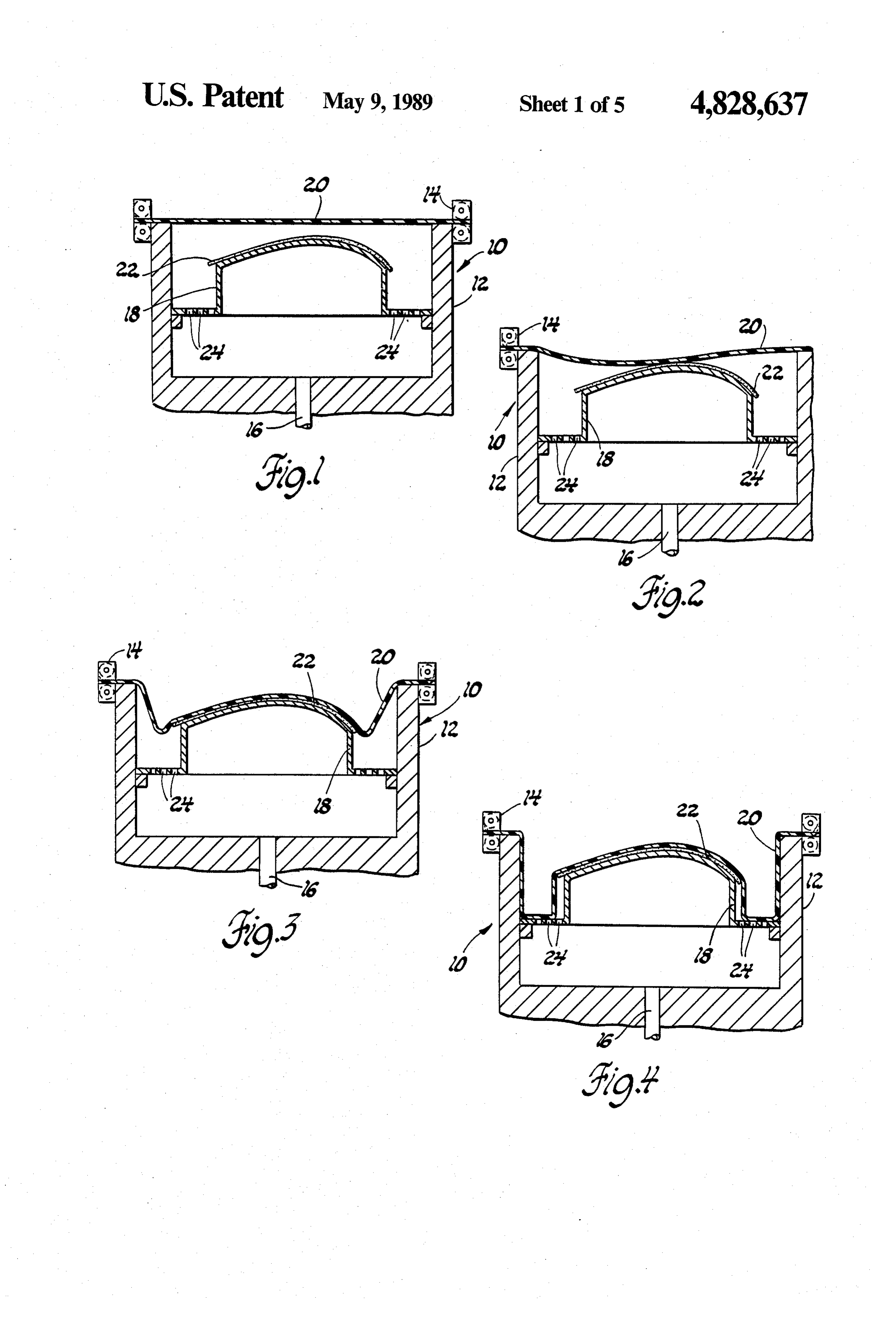
We have discovered that one possible solution to BRIEF DESCRIPTION OF THE DRAWINGS remedy the deterioration in gloss is by using a clear coat. Clear coats of various chemical nature are avail Other objects, features and advantages of the present able in the market. However, a serious problem was invention will become apparent upon consideration of encountered when clear coats are sprayed on a 65 the specification and the appended drawings, in which: stretched carrier film covered with a color coat. We FIG. 1 is a schematic showing a vacuum forming discovered that since most clear coat formulations con setup wherein a prepainted carrier film is stretched over tain one or more organic solvents, i.e. ketones, esters, a substrate to be covered.
Page 8
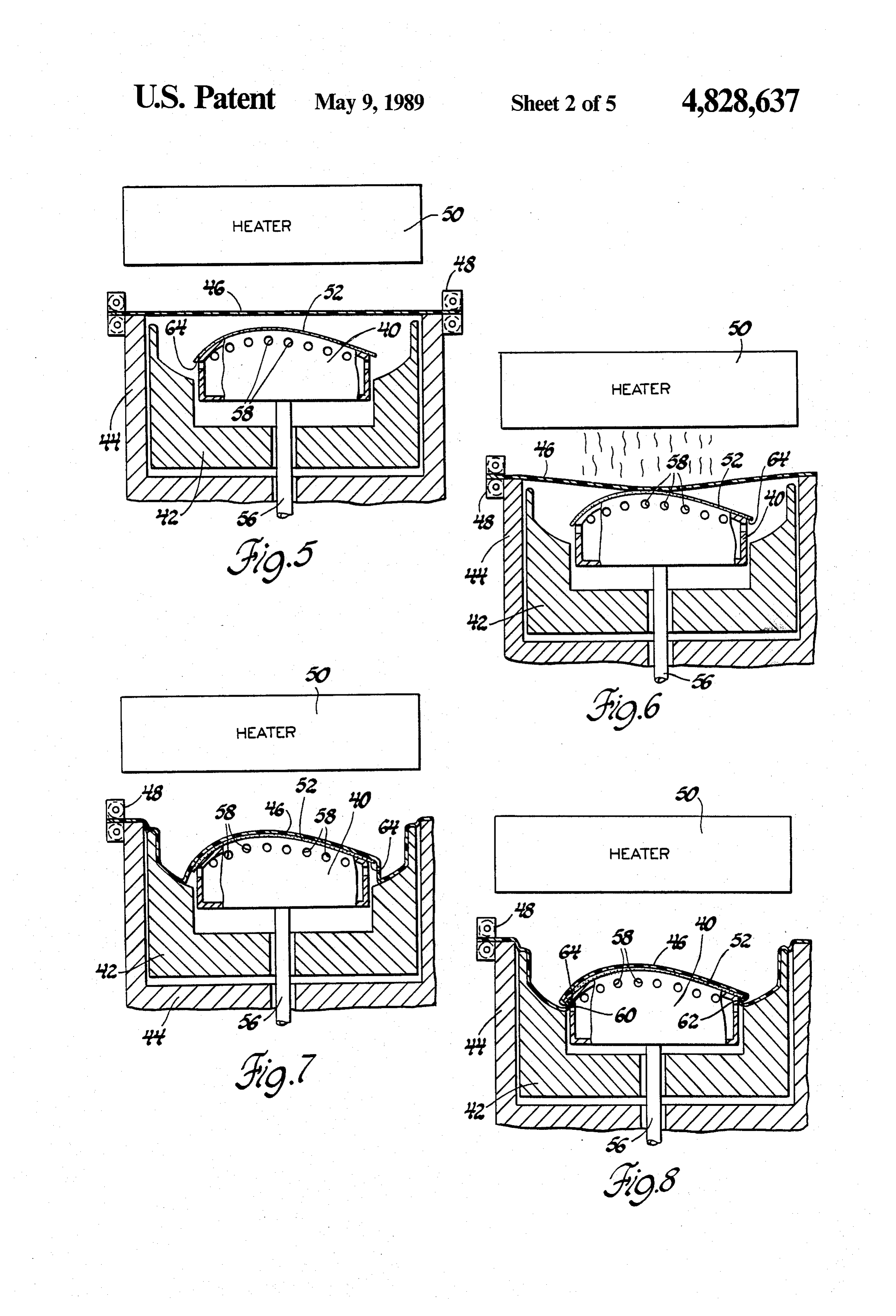
FIG. 2 is a schematic showing vacuum is applied As shown in FIG. 1, prepainted carrier film 20 is from the botton of the forming box to pull down a film clamped into a stretcher frame 14 which can be moved onto the substrate. horizontally into an oven (not shown) for heating. We FIG. 3 is a schematic showing a prepainted carrier have used an oven equipped with quartz heaters for film completely covered a substrate under vacuum. rapid heating the film to a temperature of approximately FIG. 4 is a schematic showing a prepainted film 300 F. An optical thermometer was used to monitor pulled down evenly over the edges of the substrate. the surface temperature of the film in the oven. Once FIG. 5 is a schematic showing our alternate embodi the surface temperature reaches the desirable forming ment wherein a support buck, an inner box, and an outer temperature, the stretcher frame 14 is rapidly moved vacuum box are used. 10 out of the oven and positioned over the top of vacuum FIG. 6 is a schematic showing vacuum pulled from box 12.
under the support buck after the inner box is raised. FIG. 2 shows a heated prepainted carrier film 20 FIG. 7 is a schematic showing a prepainted carrier sagging from its clamped position into vacuum box 12. film stretched down to cover the substrate and sides of Vacuum is then pulled immediately from the bottom of the inner box. 15 vacuum box 12 through vacuum port 16 to evacuate air FIG. 8 is a schematic showing the support buck in a trapped under carrier film 20.
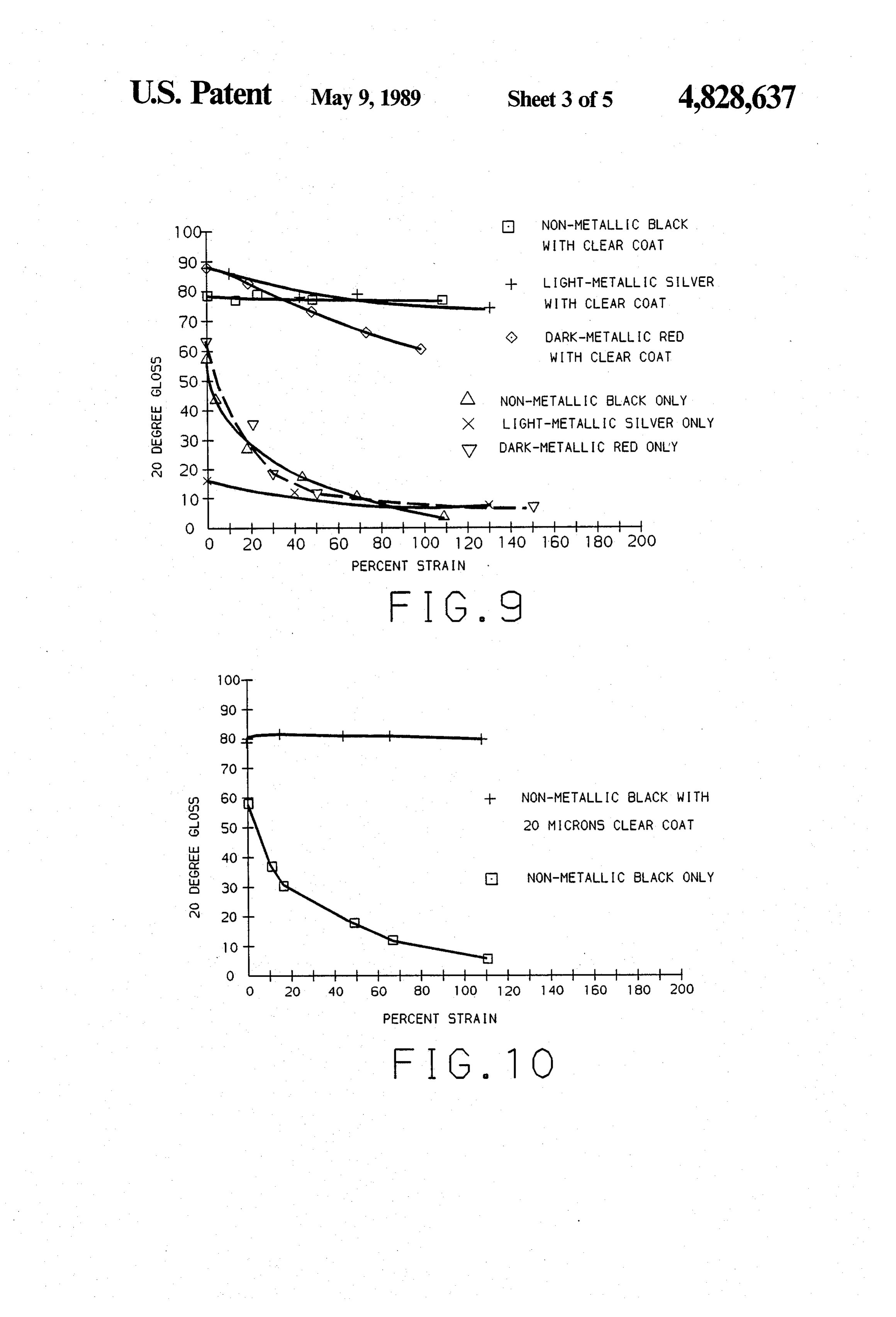
lowered position for the to edge-wrapping of the sub FIG. 3 shows that as air is evacuated out of vacuum Strate. box 12, prepainted carrier film 20 is pulled down further FIG. 9 is a graph showing the general effect of clear onto substrate 22 to cover the entire surface of the sub coat on gloss readings for color coat formulations both 20 strate. Carrier film 20 adheres to the substrate on with and without flakes. contact by the adhesive coated on the bottom surface of FIG. 10 is a graph showing the effect of 20 microns the carrier film 20.
thick clear coat on gloss readings for a non-metallic FIG. 4 shows the final stage of the vacuum forming black color coat. process wherein more air is evacuated out of vacuum FIG. 11 is a graph showing the effect of various clear 25 box 12. It is seen that film 20 is now pulled down evenly coat thicknesses on gloss readings for a medium-metal over edges of support box. 18. The substrate 22 with the lic blue color coat. prepainted carrier film 20 adhered to it can now be FIG. 12 is a graph showing the effect of various clear removed out of vacuum box 12 to trim off the excess coat thicknesses on gloss readings for a light-metallic film along the edges of the substrate. silver color coat. 30 An alternate embodiment of our invention is shown FIG. 13 is a graph showing the effect of various clear in FIG. 5-8. In this alternate embodiment a movable coat thicknesses on gloss readings for non-metallic and support buck and a movable inner vacuum box are used metallic color coats stretched at 25% strain. instead of the stationary support buck used in the previ FIG. 14 is a graph showing the effect of various clear ous embodiment. This is shown in FIG. 5 where a mov coat thickness on gloss readings for non-metallic and 35 able support buck 40 and a movable inner box 42 are metallic color coats stretched at 100% strain. mounted inside an outer vacuum box 44. Note that both DETAILED DESCRIPTION OF THE the support buck 40 and the inner box 42 are mounted PREFERRED EMBODIMENT on air cylinders which can be moved up and down as desired. FIG. 5 also shows a prepainted carrier film 46
Referring initially to FIG. 1 where a schematic of a mounted in stretcher frame 48 which can be moved vacuum former 10 is shown. Vacuum former 10 is con rapidly in and out of a heater 50. At the start of the structed of a vacuum box 12, a stretcher frame 14, a forming cycle, (FIG. 5), substrate 52 for a body part is vacuum port 16, and a support buck 18. A prepainted placed on support buck 40 with the support buck 40 in carrier film 20 is first loaded into stretcher frame 14 its up position. The prepainted carrier film 46 is pre with the paint side up. A substrate 22 which is to be 45 pared similarly as in the previous embodiment. The covered by the prepainted carrier film 20 is loaded onto carrier film 46 is placed under heater 50 until the surface support buck 18. The support buck 18 is mounted on a temperature of the film reaches 300' F. and starts sag vacuum plate 24 for the evacuation of air trapped under ging. It is then rapidly moved out of the heater and prepainted carrier film 20. The substrate 22 may be positioned over vacuum box 44. The support buck 40 is constructed of any material selected from reaction in 50 rapidly raised such that carrier film 46 touches the high jection moldable urethanes, reaction injection moldable est point of substrate 52. Vacuum is drawn through nylons, glass fiber reinforced sheeting molding com vacuum port 56 to evacuate trapped air under carrier pounds, injection moldable thermoplastics, and metals. film 46. The evacuation of air is carried out by pulling The carrier film we have used was either an extruded vacuum around the edges of the substrate 52 through polyurethane film supplied by Dow Chemical Com 55 vacuum holes 58 drilled in the top edge of support buck pany or a thermoplastic polyester film supplied by East 40, man Chemical Products. The thickness of the film is FIG. 7 shows prepainted carrier film 46 continues to approximately 0.010 inch. The backside of the film was be drawn down onto the substrate 52 and adheres to it coated with a commercial adhesive that is either heat on contact with no air entrapment. As the carrier film activated or pressure sensitive. The carrier films were 46 reaches the edges of substrate 52 and continues to be coated by either a spray-paint process or a roll-coat drawn down onto the sides of support buck 40, it cre process with a red metallic paint supplied by the PPG ates a stretched film section between the edges of the Industries, Durethane (R) 101. The size of the film sam substrate and the sides of the support buck 40. In the ples used was approximately 60 centimeters by 60 centi final step of our stretch forming process as shown in meters. Some of the carrier films were hand sprayed to 65 FIG. 8, support buck 40 together with substrate 52 on it an average coating thickness of between 0.001 and 0.004 are dropped approximately one inch causing the inch. The cure conditions used for these prepainted stretched carrier film 46 to droop at 60. As air being carrier film were 110 C. and 30 minutes. continuously withdrawn from the cavity between sup
Page 9
port buck 40 and inner box 42, the stretched carrier film lem arises when such attempt is made. We have discov 46 is pulled under the substrate 52 at 62 where it adheres ered that since the stretched surface of the color coat on contact to the backside edges 64 of substrate 52. This layer is under stress, the spraying of a clear coat layer last step of the stretch forming process wherein support on top of the color coat layer after stretching can cause buck 40 and substrate 52 are both dropped accomplishes severe stress-cracking problems. Since most clear coat an important task of edge-wrapping the carrier film to formulations that are commercially available contain the backside of the substrate. This, when done in an one kind of organic solvent or another, these organic automated manner, greatly saves the manual labor oth solvents initiate cracks in the stressed color coat layer. erwise required to edge wrap each substrate. The sub It is, therefore, our novel discovery that for most strate with the prepainted carrier film adhered to it may 10 clear coat systems, in order to use a clear coat layer to now be removed for trimming operation. improve the gloss on a dull surface of a stretched color It should be noted that even though we have demon coat, the clear coat layer should be applied on top of the strated our process with a large substrate member such color coat layer prior to the stretching process and, as an automobile body panel, our novel process can be further, should be cured by baking to completely re used for any automobile body panels, large or small. 15 move the organic solvents contained in the clear coat For instance, large body parts such as panels for a door, formulation prior to such stretching. hood, or truck lid etc. and small body parts such as body It is also our novel discovery that in order to improve side moldings can all be made by our novel process. the gloss appearance of the color coat after stretching We discovered that during our stretch forming pro or, in other words, to retain substantially the same color cess, a deformation of between 20% to 150% has oc 20 and gloss appearance of the color coat as prior to such curred in the stretched carrier film and in the color coat stretching, a critical minimum thickness of the clear layer when the film sagged after heating and then pulled coat must be applied on top of the color coat layer. By by vacuum onto the substrate. The contour and config substantially retaining the same color and gloss appear uration of the automobile part determines largely the ance of the color coat as prior to such stretching, we extent of localized deformation of the carrier film. 25 mean that in general, parameters such as the 20 gloss We also used the term "facing sheet' to define a reading does not deteriorate by more than 20 to 30, and carrier film that is coated with at least one layer of a parameters such as the colorimeter reading of L, A, B color coat and at least one layer of a clear coat. We values, do not vary by more than E1.
discovered that in order to retain substantially the same We have found that when the 20 gloss reading does color appearance of the facing sheets after stretching as 30 not deteriorate by more than 20 to 30 from the initial prior to stretching, a clear coat layer must be added on value before stretching and when the L, A, B values do top of the color coat layer prior to the vacuum thermo not change by more than 1, the color and gloss ap forming process. One of the clear coat formulations we pearance of the stretched facing sheet remains accept used is supplied by PPG Industries (UEC-1000). UEC able under normal visual examination.
1000 is a melamine cured polyester clear coat applied at 35 It is a further novel discovery that the critical mini a viscosity of 30 sec. on a Fisher #2 viscosity cup. The mum thickness of clear coats required in order to retain viscosity was reduced to this value by the use of methyl substantially the same color and gloss appearance of our ethyl ketone. We have discovered that to achieve facing sheet after stretch as prior to such stretch is de proper curing of UEC-1000, it is necessary to add 5% pendent upon several parameters. by weight of an aromatic sulfonic acid catalyst solution. First, we have classified color coats into two main One such catalyst is supplied by PPG as PPG 900-1616. categories, i.e. the color coat formulations containing It is a sulfonic acid catalyst supplied as 30% solids in additive of flakes and color coat formulations contain isopropanol. It can be suitably used in the range of 2.5 to ing no additive of flakes, (generally known as metallic 7.5 volume percent of the clear coat. The catalyst al paint and non-metallic paint, respectively). The first lows the clear coat layer to cure under the same condi 45 parameter that the critical minimum thickness required tions as the Durethane (R) 101 topcoats. Durethane (R) for the clear coat layer is dependent upon is the type of 101 is a melamine cured polyster-polyurethane solvent color coat formulations, i.e. whether it contains flakes based topcoat supplied by PPG at a viscosity range of or not. By flakes, we mean flakes either of metallic 21 to 23 sec. Fisher #1 viscosity. The viscosity was nature such as aluminum or iron flakes or non-metallic reduced to this value by the use of xylene and toluene. 50 flakes such as mica or other mineral type flakes. In our vacuum thermoforming process where a pre FIG. 9 is a graph showing the general effect of add painted carrier film is assembled to an automobile body ing a clear coat layer on a stretched color coat layer as part, a two dimensional film must be stretched in order measured by the 20 gloss readings at various percent to conform to the surface of a three dimensional auto strain levels. The effect of clear coat on three colors, mobile body part. As a consequence of this stretching 55 namely non-metallic black, light metallic silver and process, the color and gloss appearance appearance of dark metallic red is shown.
the prepainted carrier film is degraded or deteriorated. It is seen in FIG. 9 that without the clear coat layer, We have found that one simple measurement of the the gloss readings of all three colors suffered severe appearance is the measurement of the 20 gloss readings degradation to unacceptable values even at relatively by using a Gardner 20 gloss meter. When a color coat low percent strain levels. It is our experience that for on a prepainted carrier film is stretched, the shinny most colors used in painting automobile body parts, a surface of the color coat layer becomes dull. This degra value between 50 to 70 in 20 gloss readings would be dation in the gloss readings of the color coat makes the considered acceptable.
color appear different after the stretching process in In FIG. 9, it is seen that without clear coat the gloss curred in vacuum thermoforming. 65 readings of all three colors degraded to only 10 when One method to remedy the problem of the degrada the facing sheets are stretched to a strain of 100%. tion in gloss is to spray a clear coat layer on the When clear coats are added onto the color coats, all stretched color coat surface. However, another prob three colors exhibited acceptable gloss readings at
Page 10
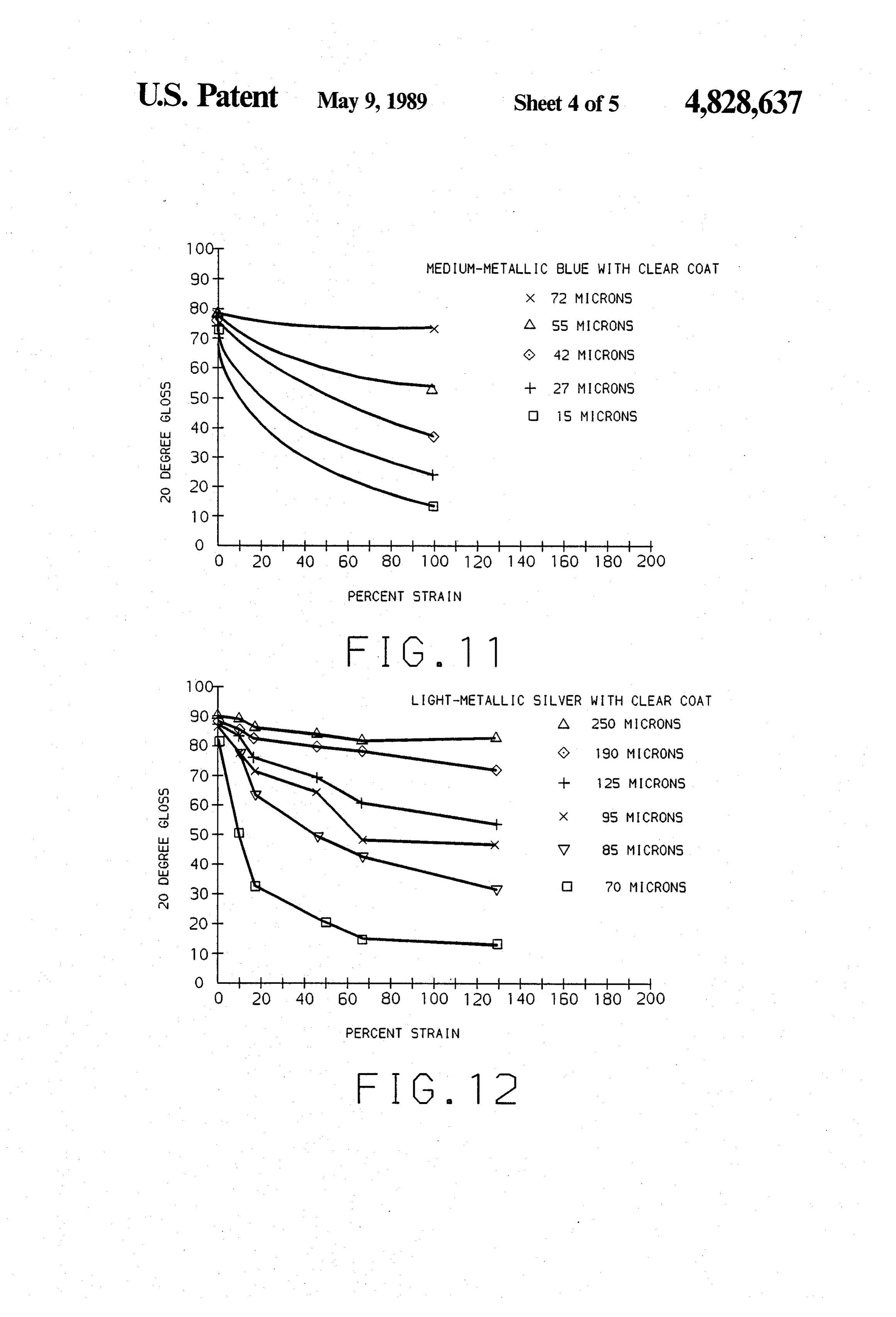
higher than 65 at 100% strain. It should be noted that thickness of clear coat would be necessary for the the thicknesses of the clear coat layers applied on the stretched facing sheet coated with the medium metallic three different colors are not the same. blue color coat.
For color coat formulations that do not contain addi The critical minimum thickness of clear coat required tives of flakes, i.e. generally known as non-metallic is the largest in a light metallic color coat. For instance, paints, the critical minimum thickness of the clear coat in a light metallic silver color coat containing 22 pounds layer required in order to retain substantially the same flakes in 100 pounds resin which relates to a flake con color and gloss appearance is small. tent of approximately 18 weight percent, the thickness FIG. 10 shows the effect of clear coat on such a of clear coats required in order to retain substantially color, i.e. non-metallic black. It is seen that without 10 the same color and gloss appearance as prior to stretch clear coat, the 20 gloss reading dropped to approxi ing is significantly higher than that required for the dark mately 25 at 25% strain and to approximately 10 at metallic and medium metallic color coats. 100% strain. Neither of these readings would have been FIG. 12 shows the critical minimum clear coat thick acceptable on an automobile body part. When 20 mi ness required for the light metallic silver color coat. It is crons thickness clear coat is applied on the color coat 15 layer and cured with the color coat layer prior to the seen cent that when the facing sheet is stretched at 100 per strain, in order to maintain a 20 gloss reading at stretching process, the 20 gloss readings of non-metal between 50 and 60, 125 microns thickness of clear coat lic black remain substantially unchanged at a reading of is necessary. When 80 when the facing sheet is stretched to strains as high lower percent strain the of facing sheet is stretched to a 25 percent, only approximately as 100%. We have observed a similar effect in other 20 non-metallic colors such as white, beige, brown, etc. tain a gloss reading between 50coat 75 microns thickness of clear is required to main
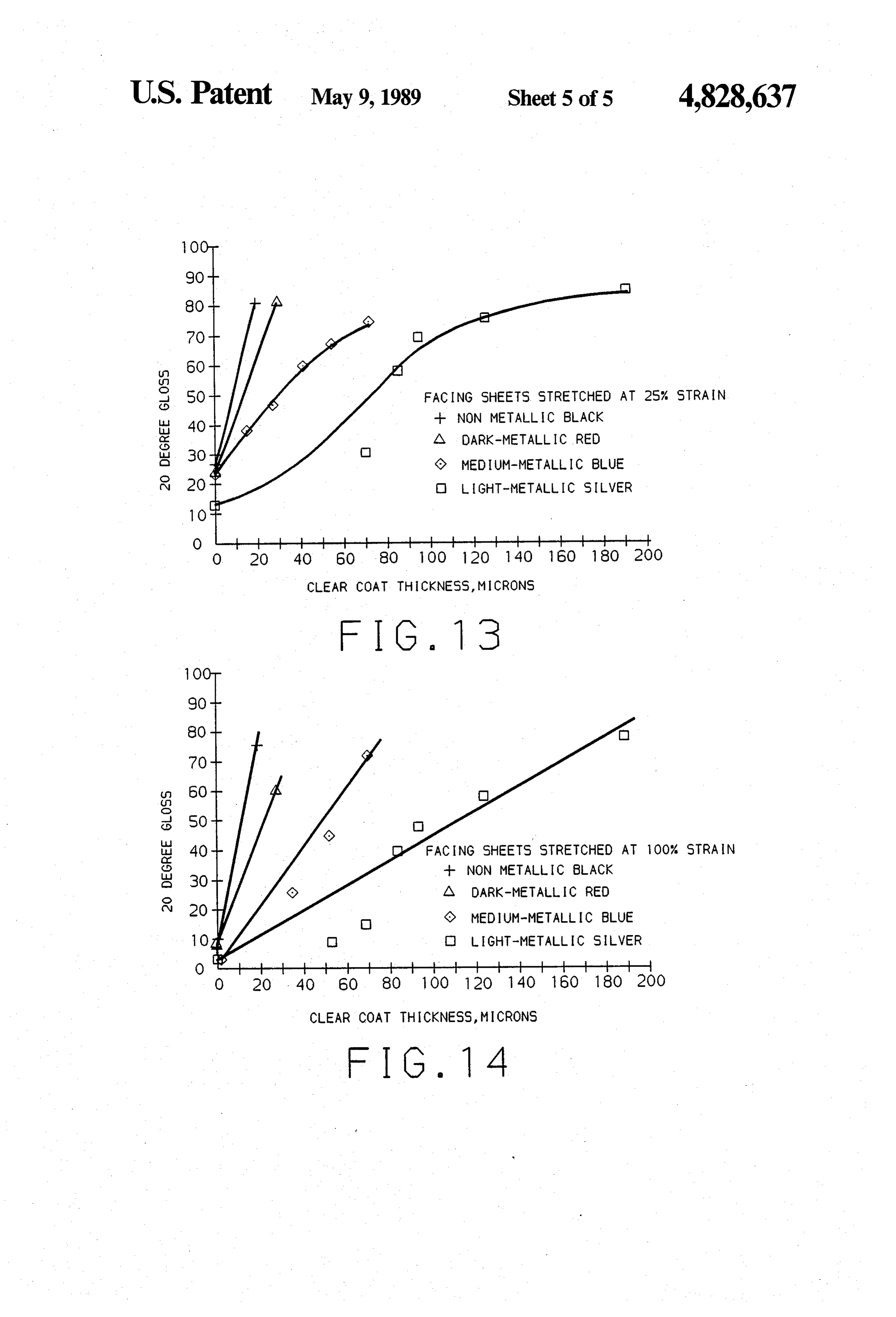
For color coat formulations that contain additives of FIGS. 13 and 14 further show the effect of clear coat flakes, i.e. generally known as metallic paints, we dis thickness on the 20 gloss reading for four different covered that the critical minimum thickness of the clear coat layer required in order to retain substantially the 25 colors, namely, a non-metallic black, a dark metallic same color and gloss appearance is much larger. In the red, a medium metallic blue and a light metallic silver color coat at two different strain levels of 25 percent normal range of clear coat thickness applied in produc and 100 percent. It is seen (FIG. 14) that in order to tion automobile body parts of between 10 to 20 microns, there was absolutely no improvement in the gloss and achieve a maximum gloss reading of 80 for the light color appearance in the color coat on a stretched facing 30 metallic silver color coat stretched at 100% strain, a sheet. It is, therefore, our novel discovery that a much minimum of 180 microns thickness of clear coat is re higher range of thicknesses of the clear coat layer is quired. Similarly, for the same color coat stretched at required in order to retain substantially the same color 25% strain (FIG. 13), a minimum thickness of 150 mi and gloss appearance of a color coat containing addi crons of clear coat is required to achieve the maximum tives of flakes. For color coats containing additive of 35 gloss reading of 80.
flakes, i.e. metallic paints, we made a thorough study on We have discovered that for a non-metallic paint that the effect of clear coat on the color and gloss appear incontains no flakes, i.e. a non-metallic black color coat, order to retain substantially the same color and gloss ance for metallic paints of different colors and for differ ent strain levels after stretching. appearance at a 20 gloss level between 50 and 60, a We have discovered that in general, the higher the minimum clear coat thickness of 10 microns is required. flake content of the metallic paint, the larger the clear To achieve a maximum gloss reading on a stretched coat thickness is required in order to retain the color non-metallic color coat such as white, we have found and gloss appearance of the color coat after stretching. that as high as 180 microns thickness of clear coat may For instance, for a dark red metallic paint which con be applied. This is true even though minimal improve taining twelve pounds of pigments in 100 pounds resin 45 ment is gained when the clear coat thickness applied is and the pigment containing 50% maroon pigment, 17% above 40 to 50 microns thick. transparent iron oxide, 24% manestral red, and 8% For a metallic color coat containing flakes, in order aluminum flakes of number 6 size. The total flake con to retain substantially the same color and gloss appear tent of this dark red metallic paint is less than 1 weight ance as prior to the stretching process, i.e. maintaining percent. In a medium blue metallic paint containing 15 50 a 20 gloss reading at between 50 and 60, a minimum pounds pigments in 100 pounds resin, the pigment por thickness of 20 microns of clear coat must be applied on tion contains 91% aluminum flakes of number 8 medi the stretched facing sheet. To achieve the maximum um-coarse size and 9% blue pigments. The total flake gloss in a light metallic color coat, as high as 180 mi content in this medium blue metallic paint is approxi crons thickness of clear coat may be used. For facing mately 12 weight percent. We have discovered that in 55 sheets stretched at a lower percent strain of 25%, a order to retain substantially the same color and gloss minimum clear coat thickness of 15 microns is necessary appearance of the medium blue metallic color coat, to maintain a 20 gloss reading on a stretched facing higher range of clear coat thickness is required than that sheet at an acceptable level between 50 and 60. At this for the dark red metallic color coat. lower percent strain level of 25 percent, as high as 120 In FIG. 11, the effect of clear coat on medium metal microns thickness of clear coat may be used in a light lic blue color coat as a variable of percent strain is metallic silver color to achieve the maximum 20 gloss shown. It is seen that at 100 percent strain, in order to reading of 80.
maintain a 20 gloss reading between 50 and 60, a clear We have found that in our vacuum thermoforming coat thickness of 55 microns is required for the process, the most severe percent strain occurred in a stretched facing sheet. This clear coat thickness require 65 contoured automobile body part is approximately 100 ment is lower when the facing sheet is stretched at a percent. In most cases where no sharp contour is in lower percent strain. For instance, at 25% strain, in volved, the percent strain seen in the stretched facing order to maintain a 20 gloss reading, only 27 microns sheet is in the range between 10 to 50 percent.
Page 11
In a mass production system as that used in the auto positioning said heated facing sheet over said sub motive industry, large rolls of carrier films are coated Strate, with at least one color coat layer and a clear coat layer drawing vacuum from under said substrate layer so and baked through a baking cycle to cure both layers that said facing sheet stretches to a strain of at least and stored for future usage when facing sheets of the 10% under said vacuum and conforms and adheres specific color is called for. Our novel invention enables to said substrate in such a way that said clear coat the complete elimination of paint facilities in an automo layer retains the gloss appearance of said facing bile assembly plant where facing sheets may be vacuum sheet at a gloss reading of at least 50 as measured by formed directly onto vehicle body parts in an auto O 3. aAGardner 20 gloss meter. method of making paint coated parts each com mated process. prising a stretched facing sheet layer and an underlying While our invention has been described in terms of a preferred embodiment thereof, it is to be appreciated substrate a top layer, said stretched facing sheet layer having surface and a bottom surface wherein said top that those skilled in the art will readily apply these surface is painted to a predetermined color with a color teachings to other possible variations of the invention. 15 coat formulation not containing any flakes and then The embodiments of the invention in which an exclu coated with at least one layer of a clear coat such that sive property or privilege is claimed are defined as the total clear coat thickness is between 10 to 180 mi follows: Crons, 1. A method of making paint coated parts each con curing said color coat and said at least one layer of prising a stretched facing sheet layer and an underlying 20 clear coat, substrate layer, method comprising the steps of: heating said facing sheet to a temperature at which providing a facing sheet layer having a top surface said sheet becomes sufficiently pliable and stretch and a bottom surface wherein said top surface is able for vacuum forming, first painted to a predetermined color by a color positioning said heated facing sheet over said sub coat formulation not containing any flakes and then 25 Strate, coated with at least one layer of a clear coat such introducing a layer of an adhesive between said that the total clear coat thickness is no less than 10 heated facing sheet and said substrate layer before microns, contacting said facing sheet with said substrate, curing said color coat and said at least one layer of drawing vacuum from under said substrate layer so clear coat, that said facing sheet stretches under said vacuum heating said facing sheet to a temperature at which at one or more predetermined locations to a strain said sheet becomes sufficiently pliable and stretch of up to 100%, able for vacuum forming, conforming and adhering said stretched facing sheet to said substrate in such a way that said clear coat positioning strate and said heated facing sheet over said sub layer retains the gloss appearance of said facing sheet at a gloss reading of at least 50 as measured by introducing a layer of an adhesive between said a Gardner 20' gloss meter.
heated facing sheet and said substrate layer before 4. A method of making paint coated parts each com contacting said facing sheet with said substrate, and prising a stretched facing sheet layer and an underlying drawing vacuum from under said substrate layer so 40 substrate layer, said method comprising: that said facing sheet stretches to a strain of at least providing a facing sheet layer having a top surface 10% under said vacuum, and conforms and adheres and a bottom surface wherein said top surface is to said substrate in such a way that said clear coat painted to a predetermined color with a color coat layer retains the gloss appearance of said facing formulation not containing any flakes and then sheet at a gloss reading of at least 50 as measured by 45 coated with at least one layer of a clear coat such a Gardner 20 gloss meter. that the total clear coat thickness is between 10 to 2. A method of making paint coated automobile parts 180 microns and said bottom surface is coated with each comprising a stretched facing sheet layer and an a layer of adhesive, underlying substrate layer, said method comprising the curing said color coat and said at least one layer of steps of: 50 clear coat, providing a facing sheet layer having a top surface heating said facing sheet to a temperature at which and a bottom surface wherein the top surface is first said sheet becomes sufficiently pliable and stretch painted to a predetermined color by a color coat able for vacuum forming, positioning formulation not containing any flakes and then 55 drawing vacuum said heated facing over said substrate, and coated with at least one layer of clear coat such from under said substrate layer so that the total clear coat thickness is no less than 10 that said facing sheet stretches under said vacuum microns and said bottom surface is coated with a pressure at one or more predetermined locations to layer of adhesive, a strain of up to 100%, conforming and adhering said stretched facing sheet curing said color coat and said at least one layer of 60. to said substrate in such a way that said clear coat clear coat, layer retains the gloss appearance of said facing heating said facing sheet to a temperature at which sheet at a gloss reading of at least 50 as measured by said sheet becomes sufficiently pliable and stretch a Gardner 20 gloss meter. e able for vacuum forming,
Provenance
- Collection
- Cited prior art
- Original PDF
- patentimages.storage.googleapis.com →
- Filed
- 1988-03-01
- Pages
- 11
- Method
- pdftotext (the PDF's own text layer) + pdftoppm 300dpi page scans
- Source
- Google Patents bibliographic record
- Granted
- 1989-05-09
- Inventors
- Charles C. Mentzer; Howard W. Cox; William T. Short; General Motors Corp
- Transcribed from
- patentimages.storage.googleapis.com →