patent · US4085709
Hydrogen fuel system for a vehicle
25 April 1978
Page 1 — bibliographic record
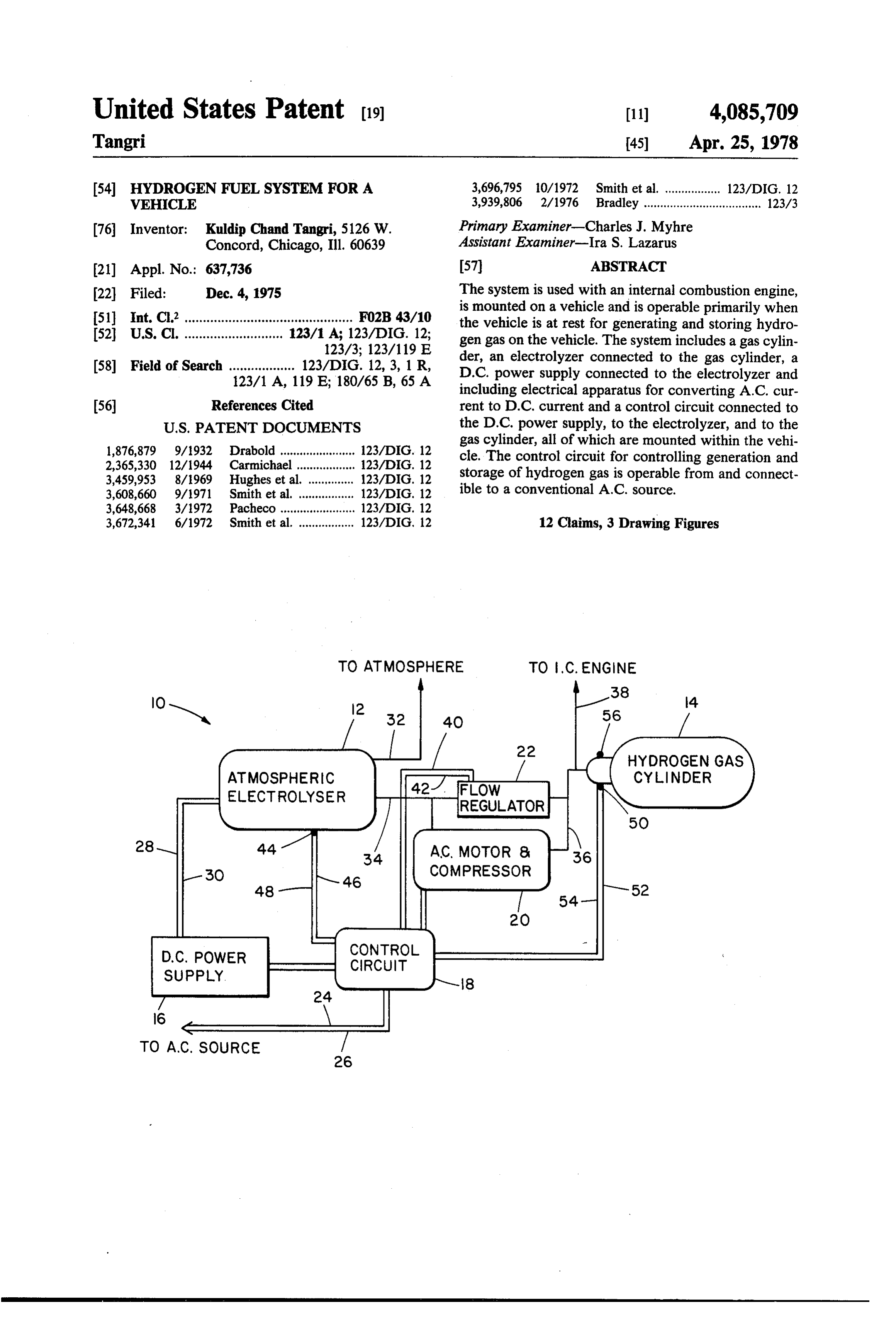
United States Patent (19) 11) 4,085,709 Tangri 45) Apr. 25, 1978 54 HYDROGENFUEL SYSTEM FOR A 3,696,795 10/1972 Smith et al. ................. 123/DIG. 12 VEHICLE 3,939,806 2/1976 Bradley .................................... 123/3 (76 Inventor: Kuldip Chand Tangri, 5126 W. Primary Examiner-Charles J. Myhre Concord, Chicago, Ill. 60639 Assistant Examiner-Ira S. Lazarus (21) Appl. No.: 637,736 57 ABSTRACT 22) Filed: Dec. 4, 1975 The system is used with an internal combustion engine, (51) Int. C.’.............................................. FO2B 43/10 is mounted on a vehicle and is operable primarily when the vehicle is at rest for generating and storing hydro (52) U.S. Cl. ........................... 123/1 A; 123/DIG. 12; gen gas on the vehicle. The system includes a gas cylin 123/3; 123/119 E der, an electrolyzer connected to the gas cylinder, a (58) Field of Search .................. 123/DIG. 12, 3, 1 R, D.C. power supply connected to the electrolyzer and 123/1 A, 119 E; 180/65 B, 65 A including electrical apparatus for converting A.C. cur 56) References Cited rent to D.C. current and a control circuit connected to
gas cylinder, all of which are mounted within the vehi 1,876,879 9/1932 Drabold ....................... 123/DIG. 12 cle. The control circuit for controlling generation and 2,365,330 12/1944 Carmichael .................. 123/DIG. 12 storage of hydrogen gas is operable from and connect 3,459,953 8/1969 Hughes et al. .............. 123/)IG, 12 ible to a conventional A.C. source.
3,672,341 6/1972 Smith et al. ................. 123/DIG, 12 12 Claims, 3 Drawing Figures
HYDROGEN GAS
ATMOSPHERC CYNDER
REGULATOR
A C. MOTOR 8
COMPRESSOR
CIRCUIT
SUPPLY 8
TO A.C. SOURCE
Page 2
TO ATMOSPHERE TO C, ENGINE
IOS
CYLNDER
ATMOSPHERC
ELECTROLYSER 427 FLOW
FREGULATOR
COMPRESSOR
D.C. POWER
SUPPLY
COMBUSTON
to N. FIG.3
HGH PRESSURE
ELECTROLYSER
HYDROGEN GAS
CYLNDER
CONTROL
D.C. POWER - CIRCUIT
SUPPLY
Page 3
HYDROGEN FUEL SYSTEM FOR A VEHICLE
combustion engine, said system being mounted on the vehicle and comprising gas storage means for storing
BACKGROUND OF THE INVENTION hydrogen gas, said storage means being connected to a 1. The Field of the Invention fuel input for the internal combustion engine, an elec trolyzer for generating hydrogen gas which is stored in
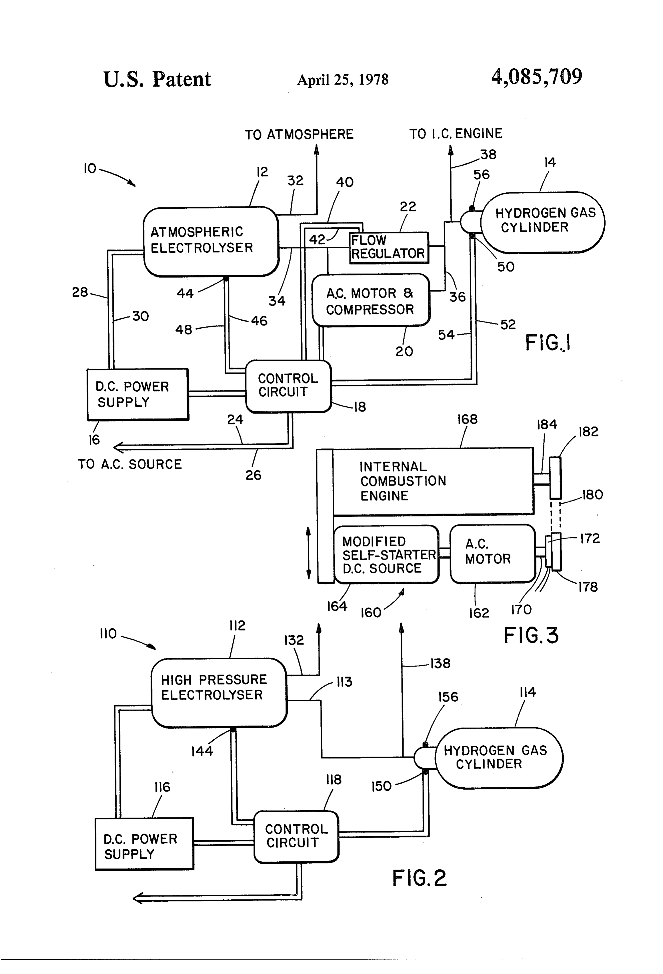
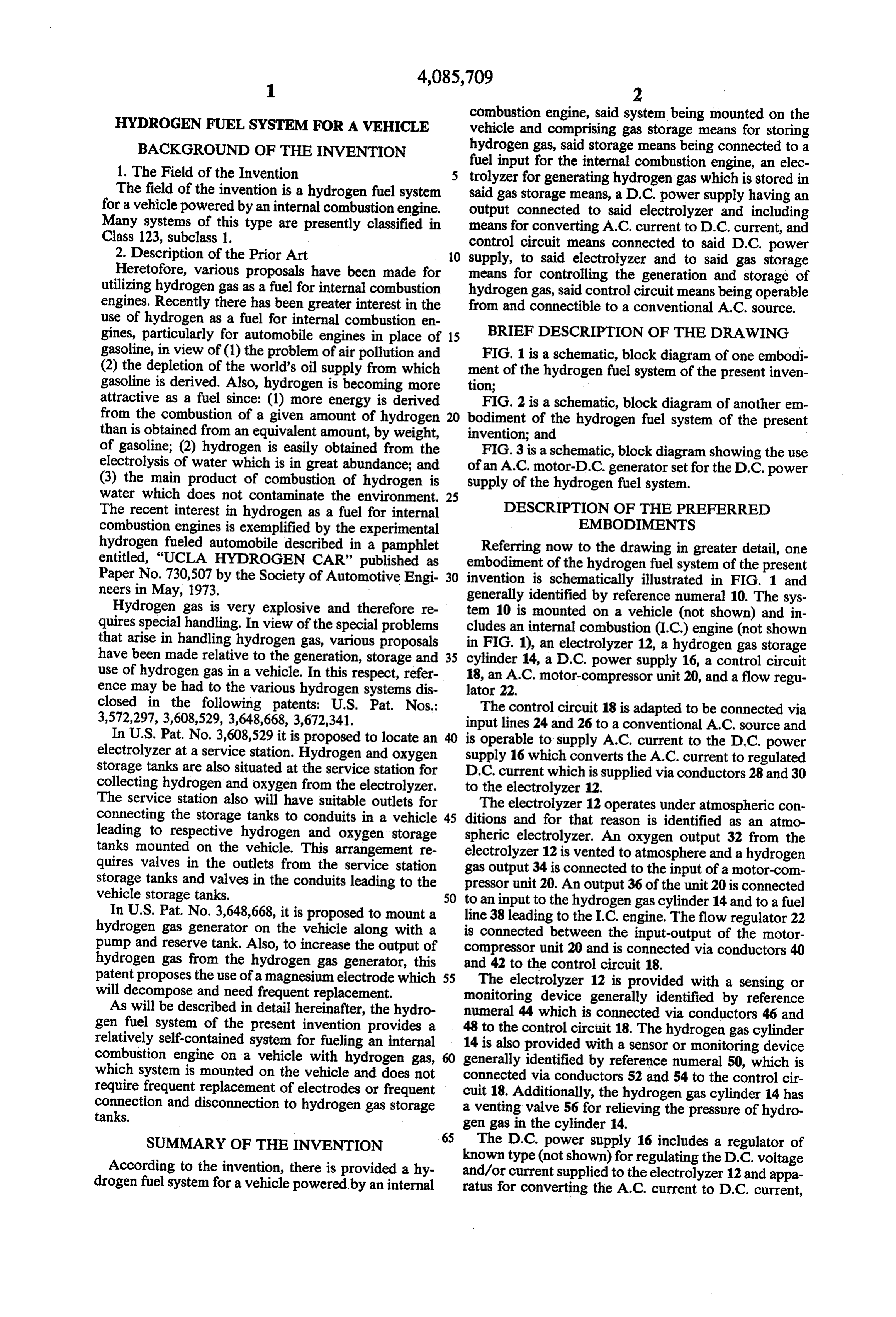
The field of the invention is a hydrogen fuel system said gas storage means, a D.C. power supply having an for a vehicle powered by an internal combustion engine, output connected to said electrolyzer and including Many systems of this type are presently classified in means for converting A.C. current to D.C. current, and Class 123, subclass 1. control circuit means connected to said D.C. power 2. Description of the Prior Art 10 supply, to said electrolyzer and to said gas storage Heretofore, various proposals have been made for means for controlling the generation and storage of utilizing hydrogen gas as a fuel for internal combustion hydrogen gas, said control circuit means being operable engines. Recently there has been greater interest in the from and connectible to a conventional A.C. source. use of hydrogen as a fuel for internal combustion en gines, particularly for automobile engines in place of 15 BRIEF DESCRIPTION OF THE DRAWING gasoline, in view of (1) the problem of air pollution and FIG. 1 is a schematic, block diagram of one embodi (2) the depletion of the world's oil supply from which ment of the hydrogen fuel system of the present inven gasoline is derived. Also, hydrogen is becoming more tion;
attractive as a fuel since: (1) more energy is derived FIG. 2 is a schematic, block diagram of another em from the combustion of a given amount of hydrogen 20 bodiment of the hydrogen fuel system of the present than is obtained from an equivalent amount, by weight, invention; and of gasoline; (2) hydrogen is easily obtained from the FIG. 3 is a schematic, block diagram showing the use electrolysis of water which is in great abundance; and of an A.C. motor-D.C. generator set for the D.C. power (3) the main product of combustion of hydrogen is supply of the hydrogen fuel system.
water which does not contaminate the environment. 25
The recent interest in hydrogen as a fuel for internal DESCRIPTION OF THE PREFERRED combustion engines is exemplified by the experimental EMBODIMENTS hydrogen fueled automobile described in a pamphlet Referring now to the drawing in greater detail, one entitled, "UCLA HYDROGEN CAR” published as embodiment of the hydrogen fuel system of the present Paper No. 730,507 by the Society of Automotive Engi 30 invention is schematically illustrated in FIG. 1 and neers in May, 1973. generally identified by reference numeral 10. The sys Hydrogen gas is very explosive and therefore re tem quires special handling. In view of the special problems cludes10anis internal mounted on a vehicle (not shown) and in combustion (I.C.) engine (not shown that arise in handling hydrogen gas, various proposals in FIG. 1), an electrolyzer 12, a hydrogen gas storage have been made relative to the generation, storage and 35 cylinder 14, a D.C. power supply 16, a control circuit use of hydrogen gas in a vehicle. In this respect, refer 18, an A.C. motor-compressor unit 20, and a flow regu ence may be had to the various hydrogen systems dis lator 22.
closed in the following patents: U.S. Pat. Nos.: The control circuit 18 is adapted to be connected via 3,572,297, 3,608,529, 3,648,668, 3,672,341. input lines 24 and 26 to a conventional A.C. source and In U.S. Pat. No. 3,608,529 it is proposed to locate an is operable to supply A.C. current to the D.C. power electrolyzer at a service station. Hydrogen and oxygen supply 16 which converts the A.C. current to regulated storage tanks are also situated at the service station for D.C. current which is supplied via conductors 28 and 30 collecting hydrogen and oxygen from the electrolyzer. to the electrolyzer 12.
The service station also will have suitable outlets for The electrolyzer 12 operates under atmospheric con connecting the storage tanks to conduits in a vehicle 45 ditions and for that reason is identified as an atmo leading to respective hydrogen and oxygen storage spheric electrolyzer. An oxygen output 32 from the tanks mounted on the vehicle. This arrangement re electrolyzer 12 is vented to atmosphere and a hydrogen quires valves in the outlets from the service station gas output 34 is connected to the input of a motor-com storage tanks and valves in the conduits leading to the pressor unit 20. An output 36 of the unit 20 is connected vehicle storage tanks. 50 to an input to the hydrogen gas cylinder 14 and to a fuel In U.S. Pat. No. 3,648,668, it is proposed to mount a line 38 leading to the I.C. engine. The flow regulator 22 hydrogen gas generator on the vehicle along with a is connected between the input-output of the motor pump and reserve tank. Also, to increase the output of compressor unit 20 and is connected via conductors 40 hydrogen gas from the hydrogen gas generator, this patent proposes the use of a magnesium electrode which 55 andThe42 to the control circuit 18. electrolyzer 12 is provided with a sensing or will decompose and need frequent replacement. monitoring device generally identified by reference As will be described in detail hereinafter, the hydro numeral 44 which is connected via conductors 46 and gen fuel system of the present invention provides a 48 to the control circuit 18. The hydrogen gas cylinder relatively self-contained system for fueling an internal 14 is also provided with a sensor or monitoring device combustion engine on a vehicle with hydrogen gas, generally identified by reference numeral 50, which is which system is mounted on the vehicle and does not connected via conductors 52 and 54 to the control cir require frequent replacement of electrodes or frequent cuit 18. Additionally, the hydrogen gas cylinder 14 has connection and disconnection to hydrogen gas storage a venting valve 56 for relieving the pressure of hydro tanks. gen gas in the cylinder 14. 65 The D.C. power supply 16 includes a regulator of
SUMMARY OF THE INVENTION
According to the invention, there is provided a hy known type (not shown) for regulating the D.C. voltage and/or current supplied to the electrolyzer 12 and appa drogen fuel system for a vehicle powered by an internal ratus for converting the A.C. current to D.C. current,
Page 4
such as rectifiers or a motor-generator set as will be A.C. motor-D.C. generator unit 160 comprising an A.C. explained in more detail in connection with the descrip motor 162 and a D.C. generator 164. The D.C genera tion of FIG, 3. tor 164 is actually a modified D.C. starter motor utilized The system 10 is operable primarily when the vehicle in starting an internal combustion engine generally iden is at rest, in other words, when the vehicle is parked in 5 tified by the reference numeral 168. The modified the owners garage. At that time the lines 24 and 26 are starter motor 164 for the I.C. engine 168 is modified by connected to a suitable A.C. source via a male-female having a compound wound stater which, through suit plug arrangement. The control circuit 18 will then ener able connections and switches, is connected as a D.C. gize the D.C. power supply 16 which provides regu motor when it is utilized for starting the I.C. engine 168. lated D.C. current to the electrolyzer 12 which in turn 10 However, it is connected as a D.C. shunt generator begins generating oxygen and hydrogen. The control when it is driven by the A.C. motor 162. It will be circuit 18 also causes operation of the motor-compres understood that when the motor-generator 164 is used sor unit 20 so that hydrogen gas at the outlet 34 of the as a starter motor, it is moved into engagement with the electrolyzer 12 is compressed and then supplied to the fly wheel for the internal combustion engine 168. How cylinder 14. 15 ever, when the engine 168 is running or is at rest, the It is to be understood that the electrolyzer 12 is of D.C. motor-generator 164 will be disengaged from the known type and the hydrogen outlet 34 has a one way fly wheel.
valve (not shown) which permits hydrogen gas to es When the engine 168 is at rest and the control circuit cape from the electrolyzer 12 but which will stop hy 18 is actuated, the A.C. motor 162 is energized and drogen gas from flowing back into the electrolyzer 12. 20 drives the D.C. motor-generator 164 as a generator. Also it is to be understood that the fuel line 38 has a The regulated output current and voltage from the valve therein (not shown) which prevents gas from generator 164 is then supplied to the electrolyzer 12 or flowing to the I.C. engine when the engine is not run 112.
ning. In this way, the cylinder 14 is filled with the hy It has been found that the fuel valve of hydrogen drogen gas produced by electrolyzer 12 and com 25 generated by electrolysis is 120% of the heating value pressed by the motor-compressor unit 20. of the electrical energy supplied to generate the hydro When a sufficient amount of hydrogen gas has been gen at 25°C. Thus, under ideal conditions a water elec generated and stored in the cylinder 14, the sensor 50 trolyzer will cause the control circuit 18 to de-energize the of up to could 120%.
have a theoretical “thermal' efficiency
This characteristic of hydrogen is more power supply 16 and the motor-compressor unit 20. 30 fully described in
Also, if an abnormality in the operation of the electro distributed by theaNational book entitled "Hydrogen as a Fuel, lyzer 12 is sensed by the sensor 44, the control circuit 18 vice of the U.S. DepartmentTechnical
Information Ser
Commerce under cata will de-energize the D.C. power supply 16 and the log no. AD-787 484, published Aug. 31, 1974. Since motor-compressor unit 20. theoretically a net gain in energy can be obtained If for some reason the electrolyzer 12 does not pro 35 duce sufficient hydrogen gas such that the motor-com through since the electrolysis-combustion of hydrogen and there are many operating conditions of a vehicle pressor unit 20 creates a vacuum at the hydrogen gas where the I.C. engine is operating at idle, it may be outlet 34, the flow regulator 22 will operate to cause economical to operate the electrolyzer 12 or 112 during hydrogen gas to be circulated through the motor-com pressor unit 20. If the amount of recirculation is exces operation of the engine 168. For this purpose, a shaft sive, the flow regulator 22 will send a signal via the clutch 170 of the A.C. motor 162 is connected via an electric conductors 40 and 42 to the control circuit 18 to cause 172 to a pulley 178 coupled by a belt 180 to a the control circuit 18 to de-energize the power supply engine 168.mounted
Suitable electrical circuitry is provided in 16 and the motor-compressor unit 20. the control circuit 18 or 118 to cause actuation of the In FIG. 2 there is illustrated a modified hydrogen fuel 45 clutch 172 when the engine 168 is running. Also, if system 110 constructed in accordance with the teach ings of the present invention. In the system 110, the desired such circuitry can be actuated only when the flow regulator 22 and the motor-compressor unit 20 are vehicle is not moving.
eliminated. Instead, the system 110 utilizes a high pres Also, to ensure adequate generation of hydrogen sure electrolyzer 112 of known type having a hydrogen 50 within a relatively constant operating temperature gas outlet 113 which is connected directly to, and range, the electrolyzer 12 or 112 can be equipped with which supplies pressurized hydrogen gas directly to, a a suitable heating or cooling apparatus. hydrogen gas cylinder 114. In other respects, the system Although conventional hydrogen gas cylinders 14 or 110 is identical to the system 10 and includes a D.C. 114 can be provided for storing the hydrogen gas, the power supply 116, a control circuit 118, an oxygen vent 55 system 10 or 110 can also utilize compartments in the 132 from the electrolyzer 112 and a fuel line 138 leading chassis or frame of the vehicle. In this respect portions from the input-output to the gas cylinder 114. Addition of the frame can be made of heavy duty metal tubes ally a monitoring device or sensor 144 is associated with providing hollow compartments therein which can the electrolyzer 112 and connected to the control cir serve as storage space for hydrogen gas generated by cuit 118. Likewise the hydrogen gas cylinder 114 has a the electrolyzer 12 or 112. Since hydrogen has a small monitor or sensing device 150 connected to the control molecule, hydrogen gas cylinders are normally thick circuit 118 and has a venting valve 156. The hydrogen and rather heavy. Thus, by utilizing thick metal tubes fuel system 110 functions in essentially the same manner not only for segments of the vehicle frame but also as as the hydrogen fuel system 10. storage space for the hydrogen gas, a space and weight As stated above, the D.C. power supply 16 or 116 65 savings can be obtained. In other words, since hollow may include static, solid-state rectifiers of known type compartments within portions of the frame are being or a dynamic, motor-generator unit for converting A.C. utilized for storing the hydrogen gas, the need for sepa current to D.C. current. In FIG. 3 there is illustrated an rate gas cylinders is eliminated.
Page 5
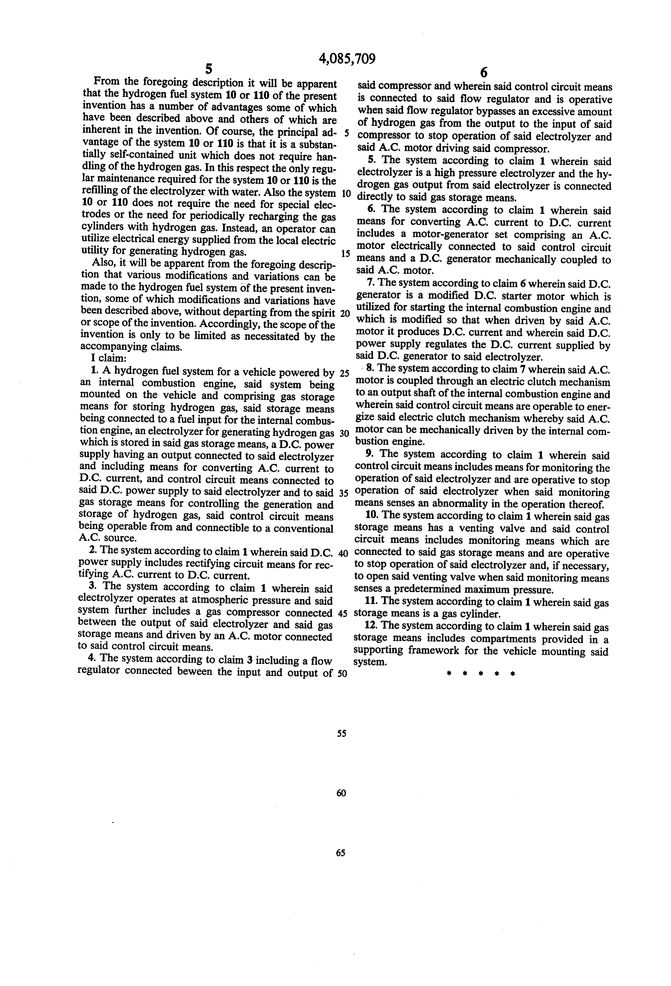
From the foregoing description it will be apparent that the hydrogen fuel system 10 or 110 of the present issaidconnected compressor and wherein said control circuit means to said flow regulator and is operative invention has a number of advantages some of which when said flow regulator bypasses an excessive amount have been described above and others of which are of hydrogen gas from the output to the input of said inherent in the invention. Of course, the principal ad compressor to stop operation of said electrolyzer and vantage of the system 10 or 110 is that it is a substan said A.C. motor driving said compressor. tially self-contained unit which does not require han 5. The system according to claim 1 wherein said dling of the hydrogen gas. In this respect the only regu electrolyzer is a high pressure electrolyzer and the hy lar maintenance required for the system 10 or 110 is the drogen gas output refilling of the electrolyzer with water. Also the system 10 directly to said gas from said electrolyzer is connected storage means.
10 or 110 does not require the need for special elec trodes or the need for periodically recharging the gas means for converting A.C. to 6. The system according claim 1 wherein said current to D.C. current cylinders with hydrogen gas. Instead, an operator can includes a motor-generator set comprising an A.C. utilize electrical energy supplied from the local electric motor electrically connected to said control circuit utility for generating hydrogen gas. 15
Also, it will be apparent from the foregoing descrip means and a D.C. generator mechanically coupled to said A.C. motor.
tion that various modifications and variations can be made to the hydrogen fuel system of the present inven 7. The system according to claim 6 wherein said D.C. tion, some of which modifications and variations have generator is a modified D.C. starter motor which is been described above, without departing from the spirit 20 utilized for starting the internal combustion engine and or scope of the invention. Accordingly, the scope of the which is modified so that when driven by said A.C. invention is only to be limited as necessitated by the power motor it produces D.C. current and wherein said D.C. accompanying claims. supply regulates the D.C. current supplied by I claim: said D.C. generator to said electrolyzer. 1. A hydrogen fuel system for a vehicle powered by 25 8. The system according to claim 7 wherein said A.C. an internal combustion engine, said system being motor is coupled through an electric clutch mechanism mounted on the vehicle and comprising gas storage to an output shaft of the internal combustion engine and means for storing hydrogen gas, said storage means wherein said control circuit means are operable to ener being connected to a fuel input for the internal combus gize said electric clutch mechanism whereby said A.C. tion engine, an electrolyzer for generating hydrogen gas 30 motor can be mechanically driven by the internal com which is stored in said gas storage means, a D.C. power bustion engine.
supply having an output connected to said electrolyzer 9. The system according to claim 1 wherein said and including means for converting A.C. current to control circuit means includes means for monitoring the D.C. current, and control circuit means connected to operation of said electrolyzer and are operative to stop said D.C., power supply to said electrolyzer and to said 35 operation of said electrolyzer when said monitoring gas storage means for controlling the generation and means senses an abnormality in the operation thereof. storage of hydrogen gas, said control circuit means 10. The system according to claim 1 wherein said gas being operable from and connectible to a conventional storage means has a venting valve and said control A.C. source. circuit means includes monitoring means which are 2. The system according to claim 1 wherein said D.C. connected to said gas storage means and are operative power supply includes rectifying circuit means for rec to stop operation of said electrolyzer and, if necessary, tifying A.C. current to D.C. current. to open said venting valve when said monitoring means 3. The system according to claim 1 wherein said senses a predetermined maximum pressure.
electrolyzer operates at atmospheric pressure and said 11. The system according to claim 1 wherein said gas system further includes a gas compressor connected 45 storage means is a gas cylinder.
between the output of said electrolyzer and said gas 12. The system according to claim 1 wherein said gas storage means and driven by an A.C. motor connected storage means includes compartments provided in a to said control circuit means.
4. The system according to claim 3 including a flow supporting system.
framework for the vehicle mounting said regulator connected beween the input and output of 50 is k is sk
Provenance
- Collection
- Cited prior art
- Original PDF
- patentimages.storage.googleapis.com →
- Filed
- 1975-12-04
- Pages
- 5
- Method
- pdftotext (the PDF's own text layer) + pdftoppm 300dpi page scans
- Source
- Google Patents bibliographic record
- Granted
- 1978-04-25
- Inventors
- Kuldip Chand Tangri
- Transcribed from
- patentimages.storage.googleapis.com →