patent · US6257175
Oxygen and hydrogen generator apparatus for internal combustion engines
10 July 2001
Page 1 — bibliographic record
(12) United States Patent (10) Patent No.: US 6,257,175 B1 Mosher et al. (45) Date of Patent: Jul. 10, 2001
(54) OXYGEN AND HYDROGEN GENERATOR 5,305,715 4/1994 Nissley ..................................... 123/3 APPARATUS FOR INTERNAL COMBUSTION 5,399,251 3/1995 Nakamats ................................. 123/3 ENGINES 5,458,095 * 10/1995 Post et al. ..................... 123/DIG. 12 (76) Inventors: Edward G. Mosher, 1641. W. Palm * cited by examiner
Cir., Bullhead City, AZ (US) 86442;
John T. Webster, 1483 Lake Shore Dr.,
Branson, MO (US) 65616
Primary Examiner John Kwon (*) Notice: Subject to any disclaimer, the term of this (74) Attorney, Agent, or Firm-H. Gordon Shields patent is extended or adjusted under 35
(21) Appl. No.: 09/310,166 Hydrogen and oxygen gases are generated for use in an (22) Filed: May 8, 1999 internal combustion engine in a vehicle using the electrical O O system of the vehicle to provide current for the electrolysis
Related U.S. Application Data process to generate the hydrogen and oxygen gases. The electrolysis process to eliminate oxygen and hydrogen gases (63) Continuation-in-part of application No. 08/929,375, filed on occurs only while the engine is being operated and termi Sep. 15, 1997, now abandoned. nates when the engine Stops. The hydrogen and oxygen (51) Int. Cl." .................................................. FO2B 43/08 gases are collected Separately in the generator apparatus and (52) U.S. Cl. ........................................... 123/3; 123/DIG. 2 flow separately in their own conduits to the intake manifold (58) Field of Search .................................... 123/3, DIG. 2 of the engine. Water in the generator apparatus is replenished from a reservoir as the water is used, and the water is (56) References Cited accordingly kept at a desired level in the generator appara tuS.
5,143,025 9/1992 Munday ................................... 123/3 39 Claims, 11 Drawing Sheets
OXYGEN -->
WATER
RESERVOR
ENGINE
Page 2
Drawing sheet — no readable text.
Page 3
Drawing sheet — no readable text.
Page 4
Drawing sheet — no readable text.
Page 5
Drawing sheet — no readable text.
Page 6
Drawing sheet — no readable text.
Page 7
Drawing sheet — no readable text.
Page 8
Drawing sheet — no readable text.
Page 9
Drawing sheet — no readable text.
Page 10
Drawing sheet — no readable text.
Page 11
Drawing sheet — no readable text.
Page 12
Drawing sheet — no readable text.
Page 13
OXYGEN AND HYDROGEN GENERATOR Among the objects of the present invention are the APPARATUS FOR INTERNAL COMBUSTION following:
ENGINES To provide new and useful apparatus for generating
CROSS REFERENCE TO RELATED
hydrogen and oxygen for internal combustion engines,
APPLICATION To provide new and useful apparatus for collecting hydro gen and oxygen gases in an electrolysis unit,
This application is a Continuation In Part application of To provide new and useful apparatus for generating Ser. No. 08/929,375, filed Sep. 15, 1997, now abandoned. hydrogen and oxygen in an electrolysis unit and for con BACKGROUND OF THE INVENTION veying the generated gases Separately to the intake manifold of an internal combustion engine;
1. Field of the Invention To provide new and useful apparatus for generating This invention relates to gas generator apparatus and, hydrogen and oxygen gases for an internal combustion more particularly, to apparatus for generating hydrogen and engine using the electrical System of the engine; oxygen gas for use in internal combustion engines. 15 To provide new and useful collector cells for collecting 2. Description of the Prior Art OXygen and hydrogen gases,
It has long been known that the pollution caused by To provide new and useful apparatus for generating internal combustion engines can be decreased by the addi hydrogen and oxygen gases for internal combustion engine tion of oxygen. As a matter of fact, in recent years the when the engine is running, and oxygenating of fuel has been mandated in various States or To provide new and useful apparatus for preventing the areas as a means for decreasing pollution. At the same time, generation of hydrogen and oxygen gas in an electrolysis it has long been known that the burning of hydrogen unit for an internal combustion engine when the engine is provides a Source of clean energy, Since the combustion of not running.
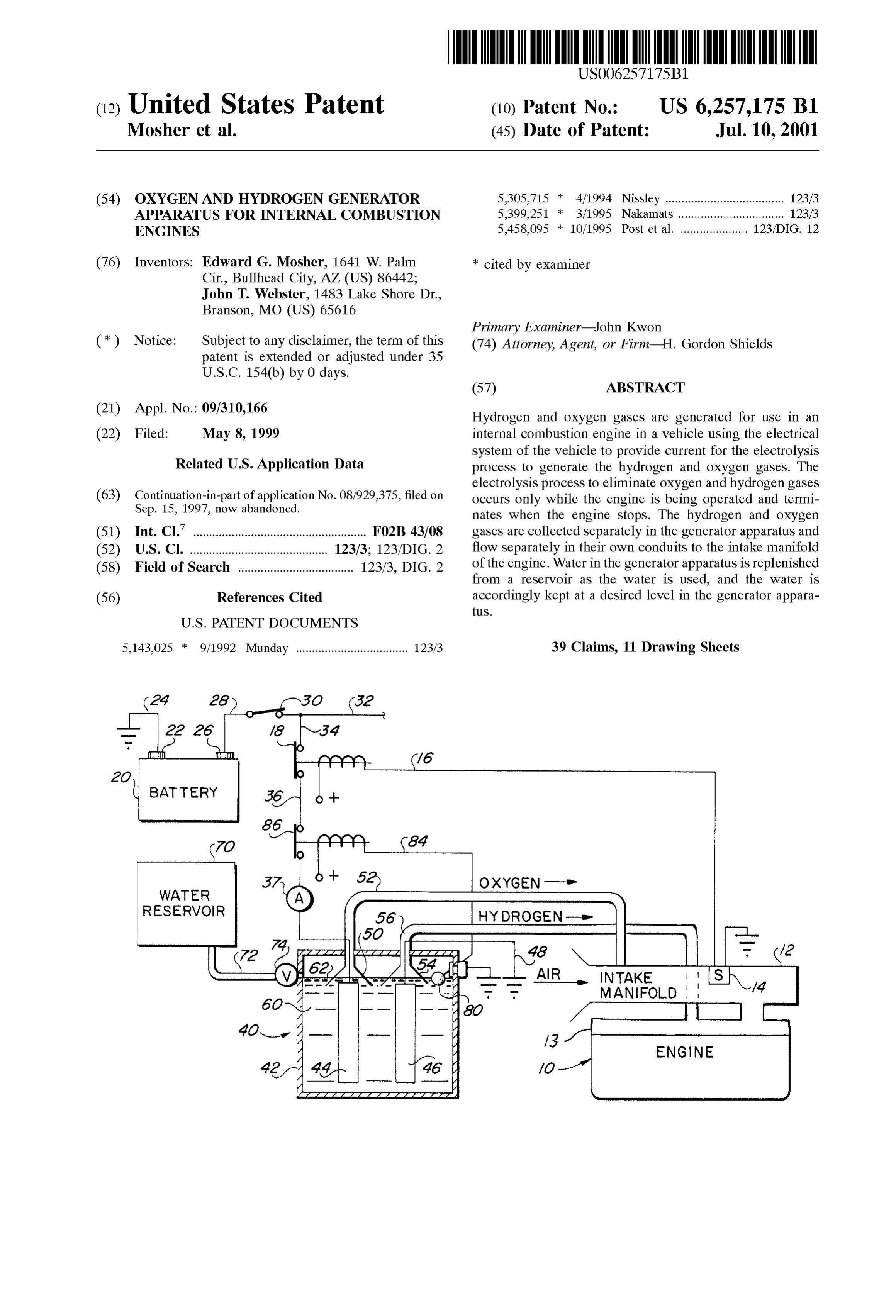
hydrogen results in the formation of water as a by product. BRIEF DESCRIPTION OF THE DRAWING Hence, the use of an electrolysis unit to generate hydrogen 25 and oxygen gases from water provides two important FIG. 1 is a Schematic representation of the present inven features, one of which is providing additional energy from tion in its use environment.
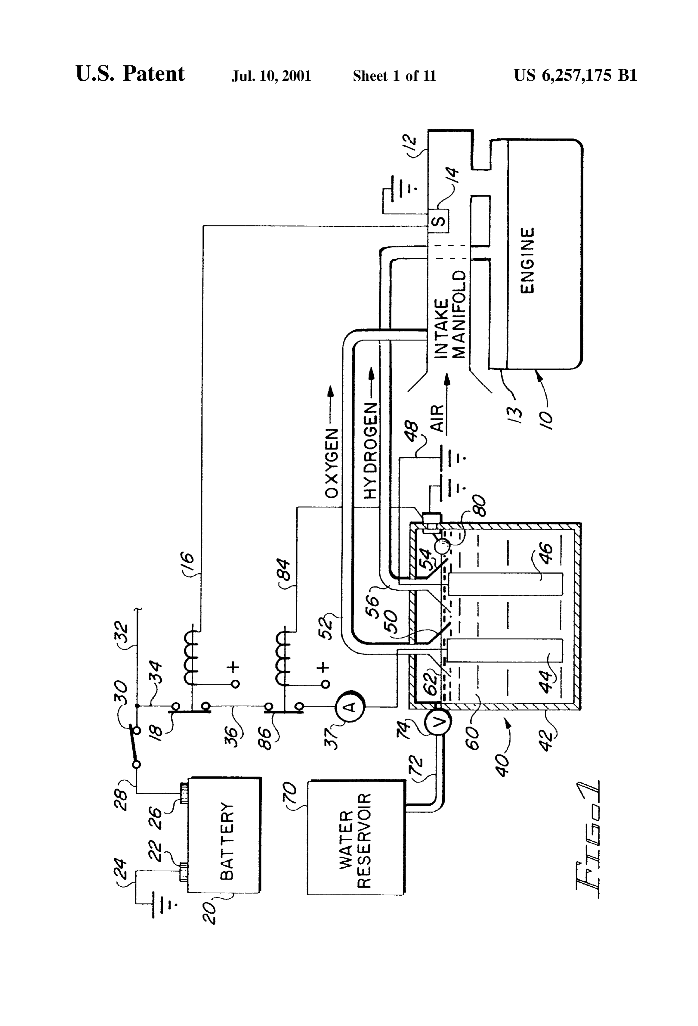
the internal combustion engine and the other of which is FIG. 2 comprises a view in partial Section through one decreasing pollution by the addition of oxygen in the com embodiment of an element of the apparatus of the present bustion process. invention.
However, it has also been recognized that there may be FIG. 3 comprises a view in partial section of another Safety problems from generating hydrogen and oxygen embodiment of an element of the apparatus of the present gases. The apparatus of the present invention generates invention.
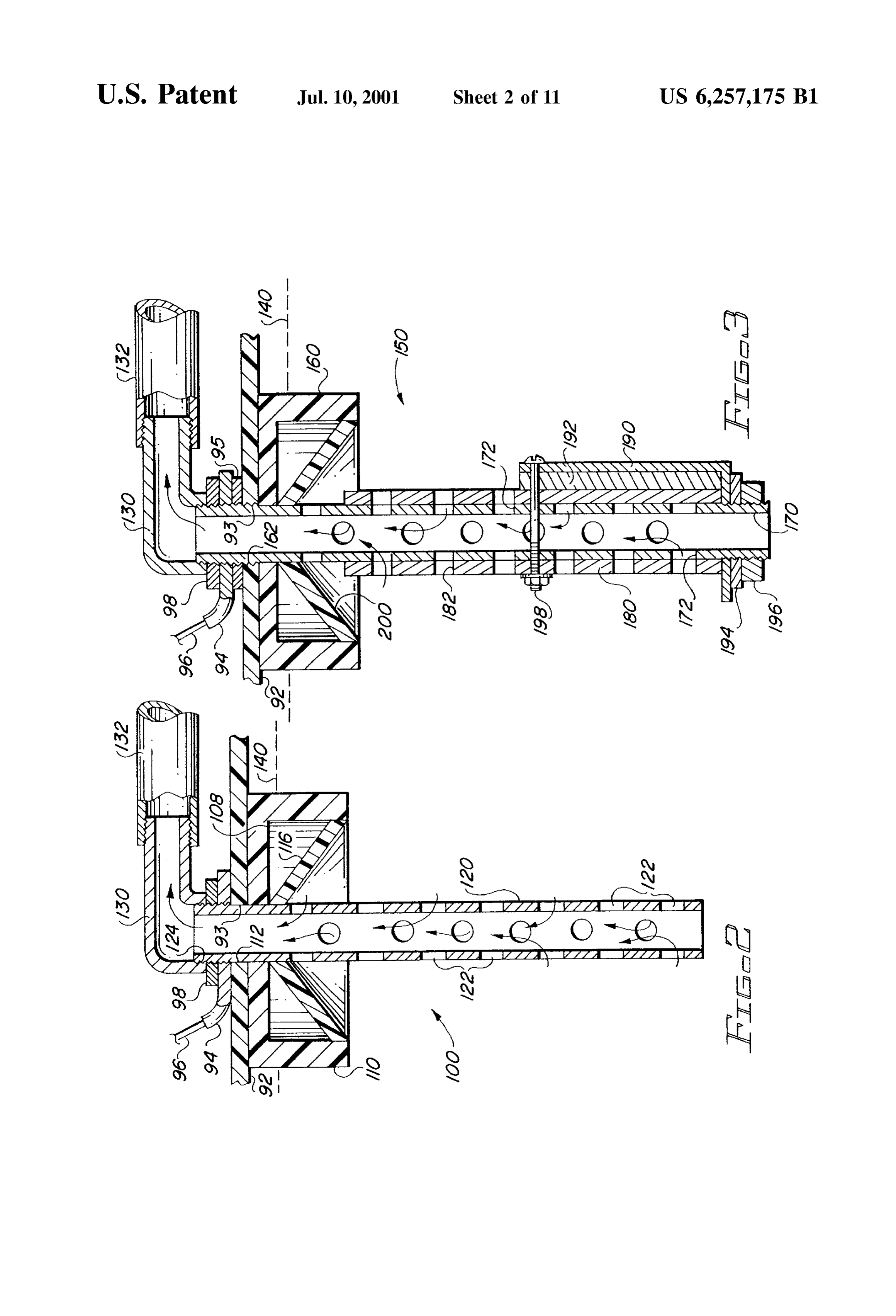
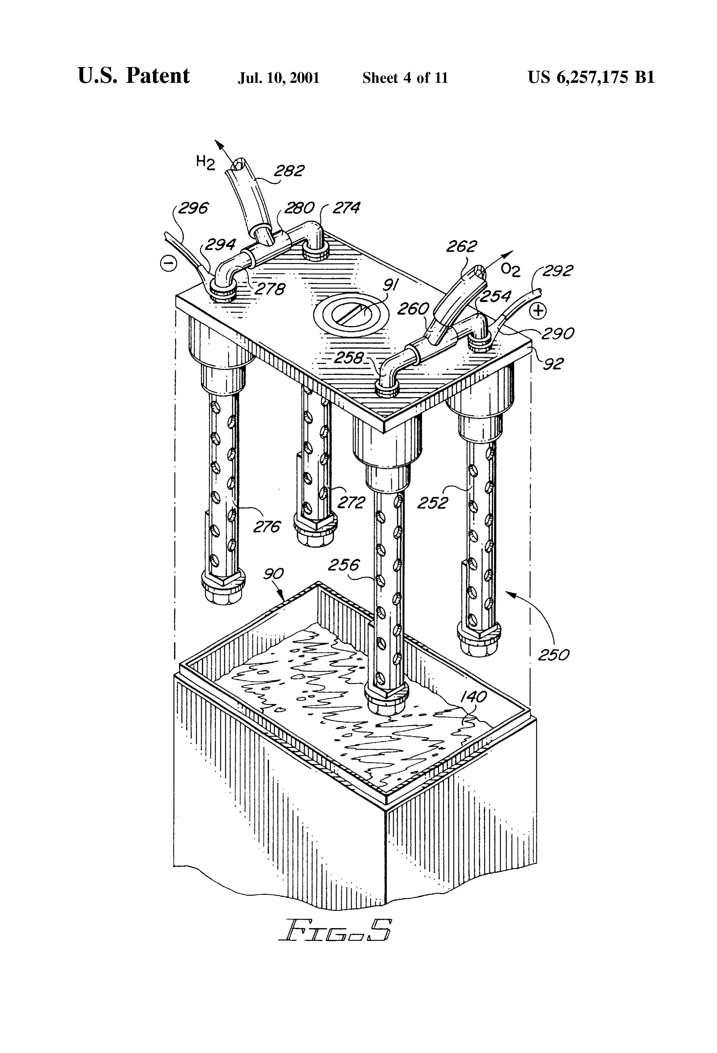
hydrogen and oxygen from an electrolysis unit and the gases FIG. 4 comprises a top Schematic representation of one are gathered Separately in the unit and flow to the engine in 35 embodiment of the apparatus of the present invention. Separate conduits, thus maximizing the Safety and at the FIG. 5 is an exploded perspective view of another Same time providing the above discussed advantages of embodiment of the apparatus of the present invention. OXygen and hydrogen gases. FIG. 6 is a view in partial section of another embodiment U.S. Pat. No. 4,023,545 (Mosher & Webster), the inven of the present invention.
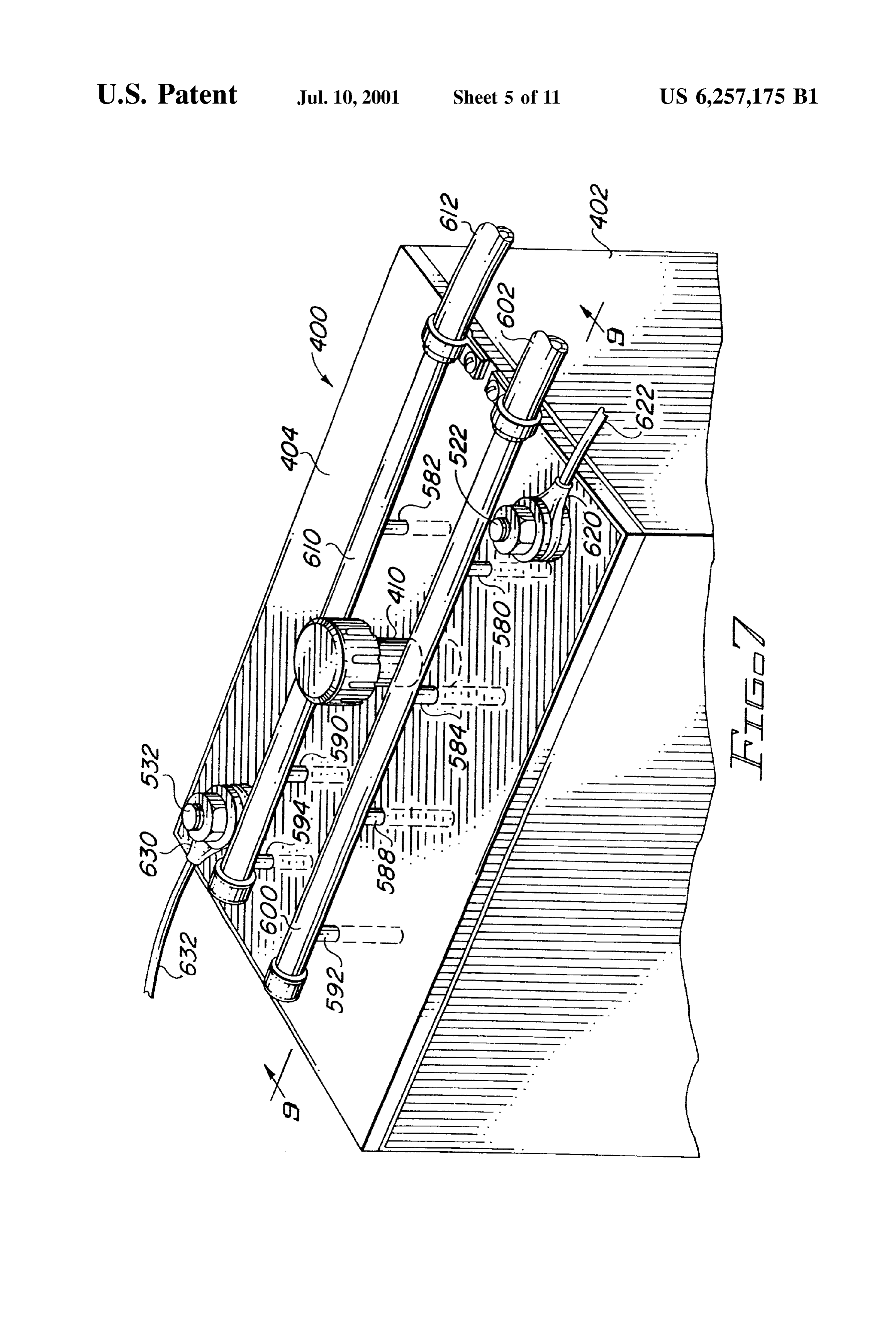
tors of which are the inventors herein, describes apparatus 40 FIG. 7 is a perspective view of another embodiment of the for generating hydrogen and oxygen for an internal com apparatus of the present invention.
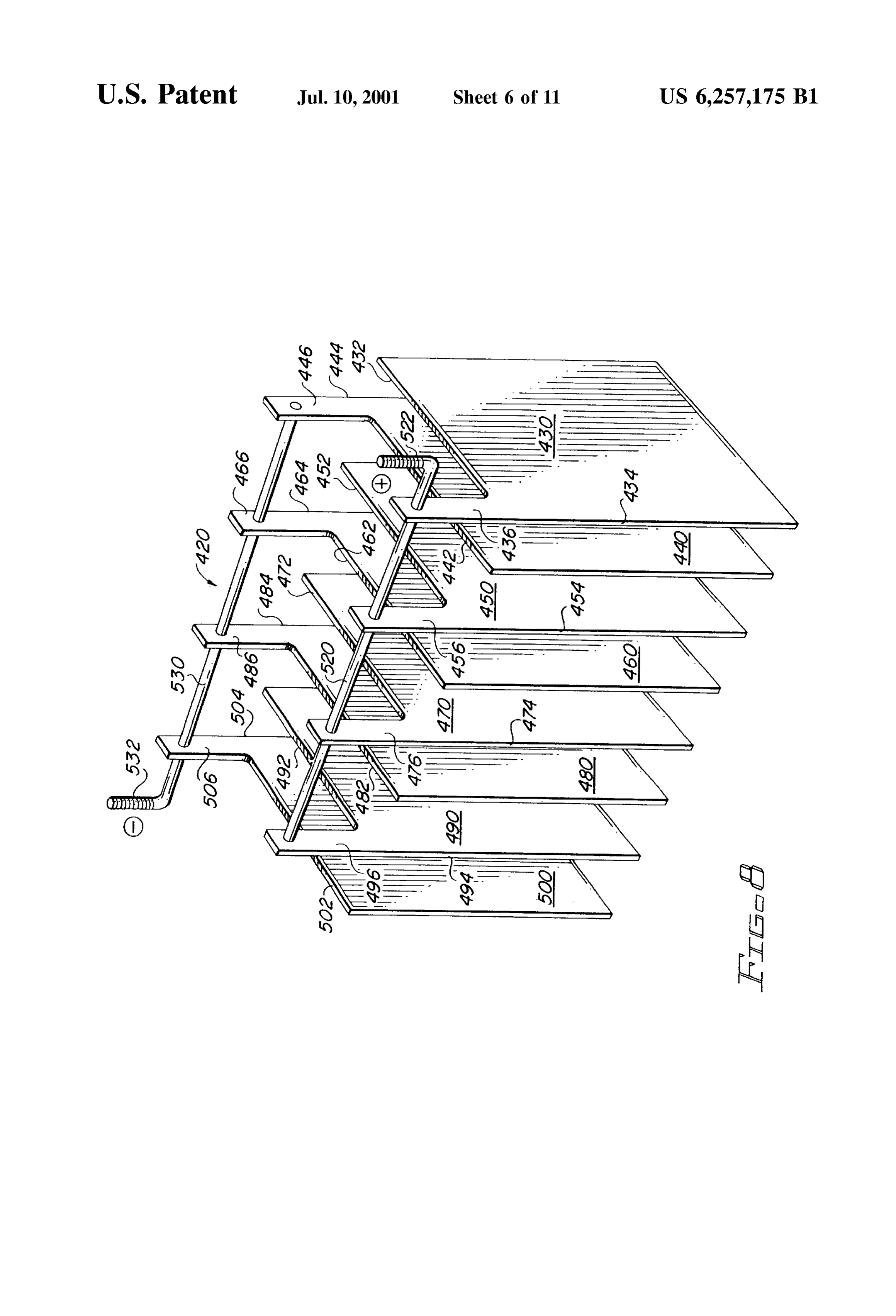
bustion engine. The hydrogen and oxygen gas is generated within a cell and flows through a conduit to the intake of FIG. 8 is a perspective view of an alternate embodiment a portion of the apparatus of the present invention.
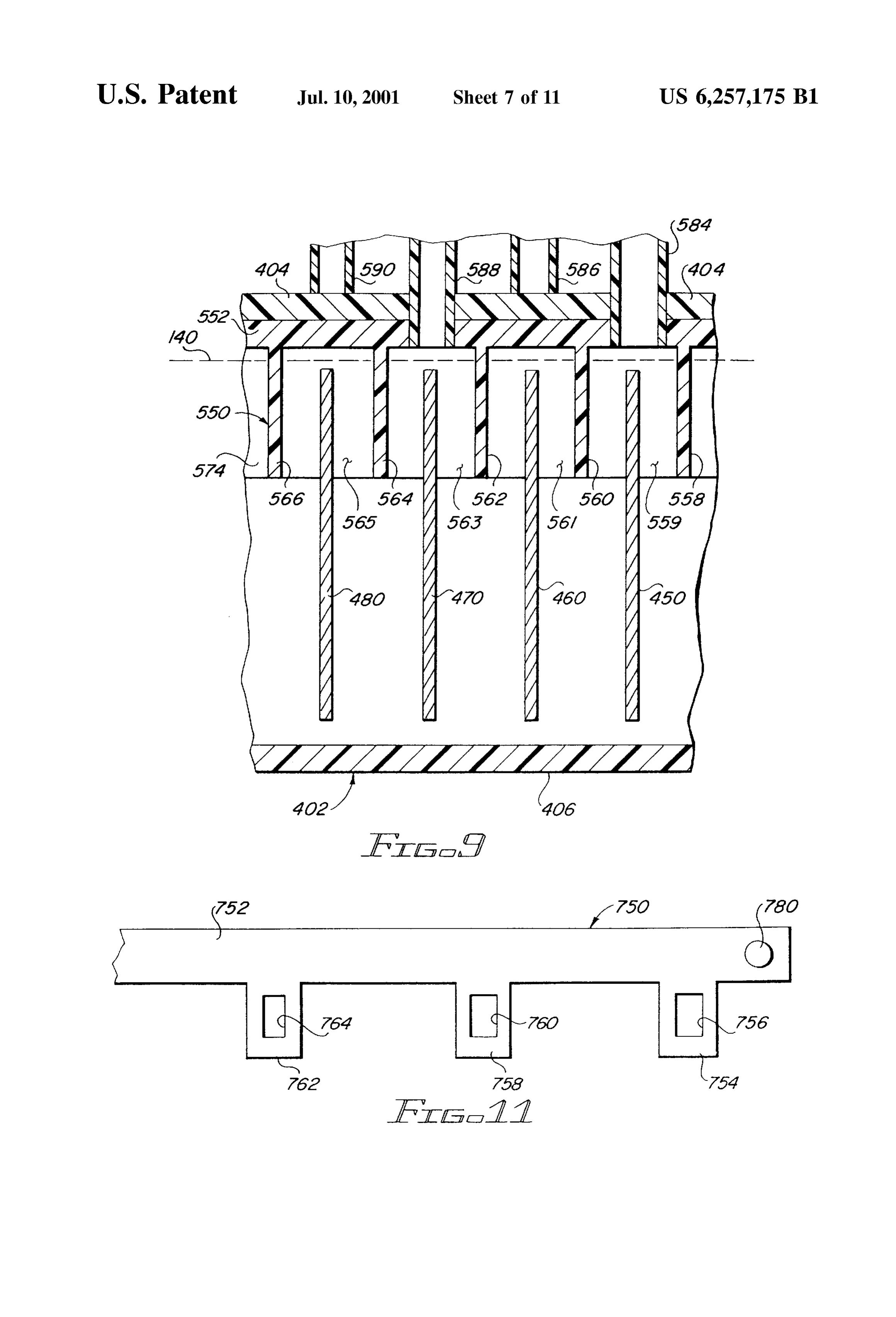
manifold of an internal combustion engine. An electrolysis, gas generating, unit is energized from the vehicle electrical 45 lineFIG. 9 is a view in partial Section taken generally along
System only when the ignition System is closed, and accord ingly only when the engine is operating. Distilled water is FIG. 10 is a view in partial section of another alternate used, with sodium hydroxide as the electrolyte. Water in the embodiment of the apparatus of the present invention. electrolysis unit is replenished from a reservoir. The elec FIG. 11 is a top plan view of a portion of the apparatus of trolysis unit, as well as the anode and cathode elements, are 50 FIG 10.
made of appropriate metal, Such as Stainless Steel, titanium, FIG. 12 is a perspective view of an alternate embodiment or other. The cathode electrode in the unit is electrically of a portion of the apparatus of the present invention. grounded to the vehicle chassis, and thus to the ground of the FIG. 13 is an end view in partial section of a hydrogen and vehicle electrical System. oxygen generator apparatus embodying elements illustrated
SUMMARY OF THE INVENTION
FIG. 14 is a fragmentary view in partial section of another
The invention described and claimed herein comprises an alternate embodiment of a portion of the apparatus of the electrolysis unit which generates hydrogen gas and oxygen present invention.
gas from water and an electrolyte, and which conveys the FIG. 15 is a side view in partial section of another two gases Separately to the intake manifold of an internal 60 embodiment of the apparatus of the present invention. combustion engine. Different embodiments are illustrated. FIG. 16 is a side view of an alternate embodiment of a An electrolyte is used in the water to provide the appropriate portion of the apparatus of FIG. 15. current flow for the electrolysis process by which hydrogen and oxygen gases accumulate on the cathode and anode, DESCRIPTION OF THE PREFERRED respectively, electrodes. Electric current is provided by the 65 EMBODIMENT electrical System of the vehicle in which the engine is FIG. 1 is a Schematic representation of an engine 10 to disposed. which apparatus 40 of the present invention is operatively
Page 14
connected. Only the elements necessary for the understand float rises, closing the valve. Such valves are, of course, well ing of the present invention will be discussed in conjunction known and understood.
with the engine 10. A float Switch 80 is included within the housing 42. The The engine 10 includes an intake manifold 12. The intake float Switch is essentially a float valve but instead of con manifold 12 provides air for the engine 10. An air flow or trolling water flow, it controls current flow in a conductor 84. vacuum valve 14 is disposed in the intake manifold 12. The A float is connected to a Switch in the conductor 84 and intake manifold 12 is also connected to hydrogen and should the water level 62 drop below a predetermined level, oxygen generator apparatus 40 of the present invention. A the float drops and opens the circuit in the conductor 84. fuel injection unit 13 is connected to the engine 10, and the The conductor 84 extends between a circuit ground and a intake manifold 12 is connected to the fuel injection unit 13. current source at a solenoid 86. The Solenoid 86 is normally A battery 20 provides electrical current for the hydrogen closed in the conductor 36, in series with the Solenoid 18, and oxygen generator apparatus 40 and for the engine 10, thus allowing current to flow to the hydrogen and oxygen and its various accessories, not shown. The battery includes generator apparatus 40.
a negative or ground terminal 22 connected to a chassis Should the fluid (water and electrolyte) level in the ground of the vehicle in which the engine 10 is disposed by 15 housing 42 drop below the predetermined minimum, the a conductor 24. The battery 20 also includes a positive float drops, opening the circuit and causing the Solenoid 86 terminal 26 to which is connected a conductor 28. The to open the circuit in the conductor 36. The apparatus 40 will conductor 28 extends to one side of an ignition switch 30. accordingly stop generating hydrogen and OXygen. Two conductors are shown connected to the other side of the ignition Switch 30, including a conductor 32 to which are generator There are at least three safety features involved with the connected all of the various accessories commonly con erator 40 will apparatuS 40 relative to the engine 10. The gen nected through a vehicle ignition Switch. A conductor 34 is when the ignition only operate to generate hydrogen and oxygen also connected to the ignition Switch 30. switch 30 is closed. Moreover, the appa The conductor 34 extends to a Solenoid Switch 18. The ratus 40 will only operate as long as there is an air flow 25 sensed through the intake manifold 12 by the air flow valve
Switch 18 is in turn connected by a conductor 16 to the air 14. Should the flow of air into the intake manifold 12 cease, flow or vacuum valve 14 in the intake manifold 12. A indicating that the engine 10 is not operating, even though conductor 36 then extends from the Solenoid 18 to an anode 44 disposed within a housing 40 of the hydrogen oxygen the ignition switch 30 is closed, the Solenoid 18 will open, preventing the generator apparatus 40 from operating.
generator apparatus 40. A cathode 46 is also disposed within the housing 42 Spaced apart from the anode 44. The cathode tiedThe to third safety feature is the water level float Switch 80, the Solenoid 86. When the water level drops below the 46 is connected to vehicle ground through a conductor 48. predetermined level, the float drops, opening the circuit in An ammeter 37 is disposed in the conductor 36. The conductor 84, causing the Solenoid 86 to open, thus turning ammeter indicates the current flowing in the electrical circuit off the generator apparatus 40.
for the electrolysis reaction which generates or liberates the 35 It will be noted that the oxygen and the hydrogen are oxygen and hydrogen gases at the anode and cathode collected Separately in the generator apparatus 40, and the electrodes, respectively. Such is well known and understood collected gases flow in Separate conduits to the intake in the art.
An oxygen collector 50 is disposed about and above the not manifold 12 and to the fuel injection unit 13. The gases are anode 44. An oxygen conduit 52 extends from the collector 40 injection mixed together prior to their introduction to the fuel 50 to the intake manifold 12. A hydrogen collector 54 is unit 13.
disposed above and about the cathode 46. A hydrogen AS is well known and understood, and as discussed above, conduit 56 extends from the collector 54 to the fuel injection oxygen may be introduced primarily to help the combustion unit 12. Thus, oxygen is introduced into the manifold 12, and processes within the engine 10 in order to reduce pollution is mixed with ordinary intake air, while the hydrogen is 45 from the exhaust of the engine 10. The hydrogen is added to introduced directly into the fuel injection unit 13 ahead of provide extra energy from the combustion processes of the the air and oxygen from the intake manifold 12. In actuality, engine 10.
the oxygen from the conduit 52 may be vented directly to the AS indicated above, FIG. 1 comprises a Schematic repre atmosphere instead of routed to the intake manifold, Since Sentation of hydrogen generator apparatuS 40 of the present there is Sufficient oxygen in the atmosphere to Sustain 50 invention connected to an engine 10. Only a Single anode 44 complete combustion in the engine 10 without the oxygen and a Single cathode 46 are illustrated within the housing 42 from the unit 40 and the conduit 52. of the apparatus 40. The anode 44 and its collector 50 Within the housing 42 is a solution of water and electro represent a Single OXygen generating cell for the apparatus lyte 60. The electrolyte may be sodium hydroxide or other 40, and the cathode 46 and its collector 54 represent a single appropriate chemical material. The level of the water and 55 hydrogen collecting cell for the generator apparatus 40. electrolyte solution is indicated by reference numeral 62. It Multi-cell generator and collector units are desirable, and will be noted that the level 62 is above the top of both the Such are illustrated in conjunction with the other FigS. of the anode 44 and the cathode 46. drawing, namely FIGS. 4, 5, and 7-9. A water reservoir 70 is disposed adjacent to the housing In the following discussed embodiments of hydrogen 42. The reservoir 70 is connected to the housing 42 by a 60 generating units, the hydrogen and oxygen gases are col conduit 72. A valve 74 controls the flow of water from the lected Separately and are separately routed to an engine as reservoir 70 into the housing 42. The valve 74 may be a discussed above.
relatively simple float Valve extending into the housing 42. FIG. 2 is a view in partial Section of a generator unit When a drop in the level 42 of the water and electrolyte uSable in the apparatus of the present invention. That is, a 60 causes the float to move downwardly, the valve 74 is 65 plurality of generator cells 100, as illustrated in FIG. 2, may opened to allow water to flow from the reservoir 70 into the be employed in a housing, of which a portion of a top 92 is housing 42. When the water reaches the desired level, the shown in FIG. 2. The housing to which the top 92 is
Page 15
S 6 illustrated may be similar to the housing 42 illustrated A terminal 94 is secured to the pipe 170 between the schematically in FIG. 1. That is, the housing may be a bottom nut 95 and a top or upper nut 98. The conductor 96 generally rectangular nonconductive housing, Such as made extends outwardly from the terminal 94 to either a positive of waterproof plastic, etc., with a bottom and four walls (not ground Source or a negative ground, as desired for any shown) extending between the top 92 and the bottom. generator cell 150, as discussed above for the cell 100. The top 92 may be appropriately sealed to the sides, with Above the nut 98 the connector 130 is threadedly secured a filler hole, vents, etc., as are well known and understood to the upper portion of the pipe 170. The conduit 132 is in in the art, all part of the top. The cell 100 is secured to the turn secured to the connector 130. Disposed about the pipe top 92 through an aperture 93 which extends through the top. 170 is a square tubing element 180. The square tubing This will be discussed in more detail below. element 180 includes a plurality of apertures 182 extending The generator cell 100 includes a cap 110. The cap 110 is through it, and preferably aligned with the apertures 172 in preferably made of plastic material, which is, of course, the pipe 170. The square tubing element 180 has inside nonconductive. dimensions equal to the diameter of the pipe 170, and The top cap 110 includes a central aperture 112 through accordingly will be tangent to, and therefore touching, the which extends a conductive pipe 120. The pipe 120 is 15 pipe 170 in four places throughout the length of the pipe and preferably made of titanium, etc. A plurality of apertures 122 the tubing.
extend through the pipe 120. The apertures 122 allow the The bottom of the pipe 170 is also threaded, and a bracket water and electrolyte solution to flow into the interior of the 196, having a generally L-shaped configuration, is Secured pipe.
The pipe 120 extends upwardly through the aperture 112 to the bottom of the pipe 170 by a washer 194 and a nut 196. The bracket 190 holds a bar of zinc 192 against the square in the cap 110 and through the aperture 93 in the top wall 92. tubing 180. The bracket 190 secures the square tube 180 to Above the wall 92, a terminal 94 is secured to the pipe 96 the pipe 170, in addition to securing the zinc bar 192 to the by a nut 98. A conductor 96 extends from the terminal 94 to tubing 180.
either a Source of positive current, if the pipe 120 is an anode The vertical arm of the bracket 190 and the Zinc bar 192 for generating oxygen, or to an appropriate circuit ground if 25 may be secured to the tubing 180 and the pipe 170 by an the pipe 120 is used as a cathode for generating hydrogen. appropriate fastener, such as a bolt 198. A connector 130 is also threadedly secured to the pipe 120 The bracket 190 is preferably made of titanium, etc., as above the terminal 94 and the nut 98. A conduit 132 is in turn are the washer 194 and the nut 196.
Secured to the connector 130. Gas, hydrogen or oxygen, generated within the cell 100 flows upwardly in the pipe 120 The purpose of the Zinc bar is to improve the electrolysis and out the connector 130 and the conduit 132 to the intake process, and to slow the deterioration of the electrodes manifold of an engine, Such as the intake manifold 12 of the within the cells. AS is well known and understood, Zinc is engine 10 illustrated in FIG. 1. typically used in watercraft for electrolysis purposes. The A generally conical collector element 116 is disposed Zinc has a direct effect of Slowing the deterioration of the about the pipe 120 adjacent to the cap 110 and at or above 35 electrode Subject to electrolysis reactions. the uppermost aperture 122 in the pipe 120. The collector Preferably all of the metal elements of the collector cells element 116 is also preferably a nonconductive element. The are made of titanium, etc. except the marine Zinc bar 192. purpose of the collector 116 is to insure that the hydrogen or The pipe 120 of the generator coil 100 of FIG. 2 is preferably oxygen gas generated at the pipe electrode 120, which, is 40 made of titanium, etc., as is the pipe 170 of the cell 150, the indicated above, may either be an anode electrode or a square tubing 180, the bracket 190, and the washer 194 and cathode electrode, flows into the pipe 120 and thus out of the nut 196, all of which are disposed below the water line 140. unit 100. Externally, the metal elements may also be made of Stainless The use of both the cap 110 and the conical collector Steel, if desired.
element 116 help to insure the integrity of the generator cell 45 At the upper portion of the pipe 170, and above the square 100. However, the cap 110 may be omitted if desired. tubing 170, and adjacent to the cap 160, is a conical collector Gas generated within the pipe 120 will naturally flow element 200. The conical collector element 200 performs upwardly within the pipe, and gas generated on the exterior substantially the same function in the cell 150 as does the of the pipe 120 will flow upwardly and will be guided collector element 116 of the cell 100. That is, the collector through the uppermost apertures 122 by the conical collector 50 element or canopy 200 insures that gas generated at the 116. electrode, on the outside of the pipe 170 and the tubing 180, The level of the water within the housing, and in which flows inwardly through the uppermost apertures 172 to the the cell 100 is disposed, is indicated by the dashed line 140. inside of the pipe 170.
FIG. 3 is a view in partial Section through an alternate It will be understood that the surface area of the pipe 170 embodiment of the generator cell 100 of FIG. 2, comprising 55 with its square tubing 180, which essentially comprises a a generator cell 150. sleeve over the pipe 170, is substantially greater than that of The generator cell 150 is similar to generator cell 100 in the pipe 170 alone. Accordingly, for the same current density that it includes a basic cap 160 and a pipe 170 secured to the applied to the electrode, which consists of the pipe 170, the top 92. An aperture 162 extends axially through the top cap tubing 180, and the zinc bar 192 and the bracket 190, more 160. 60 gas will be generated than will be generated in the cell 100 The pipe 170 extends upwardly through the aperture 162 by the pipe 120, alone and without a sleeve. and the cap 160 and through the aperture 93 and the top wall FIG. 4 comprises a top view Schematic representation of 92. The pipe 170 also extends downwardly below the cap hydrogen and oxygen generator apparatus 200 configured 160. Extending through the pipe 170 are apertures 172. with four cells in an elongated rectangular configuration. The upper portion of the pipe 170 is threaded to receive 65 The essential electrical elements are illustrated. a nut or washer 95 which secures the pipe 170 and the cell The apparatus 200 includes a housing 90, with four cells 150 to the top wall 92. 212, 214, 216, and 218 appropriately secured to the top wall
Page 16
92 of the housing 90. The cells 212, 214, 216, and 218 may terminal connector 290. The “plus” sign adjacent to the be either the cells 100 of FIG. 2 or the cells 150 of FIG. 3, conductor 292 indicates that a Source of positive current is as desired, or any other configuration illustrated herein. supplied to the electrodes within the cells 252 and 256, and Cells 212 and 216 are shown connected together by a accordingly oxygen is generated therein. conductive manifold 220. The conductive manifold is sim The cells 272 and 276 are similarly connected together by ply metal connectors, Such as the connector 130 illustrated conductive connectors 274 and 298 and a conductive tee in FIGS. 2 and 3, connected together by a metal fitting. 280. The connectors 274 and 278 and the tee 280 are Similarly, the cells 214 and 218 are connected together by a substantially identical to the connectors 254 and 258 and the metallic or conductive manifold 224. tee 260.
A flexible conduit 222 is connected to the manifold 220, A conduit 282 extends from the tee 280, and hydrogen gas while a flexible conduit 226 is connected to the manifold generated in the cells 272 and 276 flows outwardly in the 224. Oxygen and hydrogen gases generated by the cells 212 conduit 282. The gases generated by the cell pairs flow to the and 216 and the cells 214 and 218 flow separately to an engine of the vehicle in which the apparatus 250 is disposed, engine intake manifold in the conduits 222 and 226. 15 substantially as shown in FIG. 1.
A conductor 230 is connected to the cell 212 and to the A terminal connector 294 is shown connected to the cell manifold 220 to provide electrical current for the cells 212 176 and the connector 278. A conductor 296 in turn extends and 216. The conductor 230 is represented as being con from the terminal 294. The “minus' sign by the conductor nected to a Source of positive current. 296 indicates that the conductor 296 is grounded, and A conductor 232, shown as a ground conductor, is con accordingly hydrogen gas is generated in the cells 272 and nected to the cell 214 and to the manifold 224. Through the 276.
conductive manifold 224, the cell 218 is also connected to Extending through the top wall 92 is a fill port 91. The fill the conductor 232, just as the cell 216 is connected to the port 91 is used to fill the housing 90 with water and an positive conductor 230 by the conductive manifold 220. electrolyte, as discussed above.
Thus, the electrodes within the cells 212 and 216 com 25 The cells 252,256, 272 and 276 illustrated in FIG.5 may prise anode electrodes, and accordingly oxygen will be be of the structural design of the cell 150 illustrated in FIG. generated within the cells 212 and 216 and will be conducted 3, if desired. That is, a pipe with a Square tube disposed to the intake manifold of the engine through the manifold about the pipe and a bar of marine Zinc Secured to the pipe 220 and the conduit 222. may be included in the electrodes. A cap and a conical The electrodes within the cells 214 and 218 comprise collector may be disposed at the juncture of an electrode and cathode electrodes Since they are connected to the negative the housing top wall, as also discussed. or ground of the electrical system of the vehicle in which the The rectangular configuration of the cell arrangement in apparatus 212 is disposed. Accordingly, hydrogen will be the generator apparatus 250 may be used where there is more generated within the cells 214 and 218 and will be conducted physical room than is available for the elongated rectangular to the intake manifold of the engine through the manifold 35 configuration of generator apparatuS 210 illustrated in FIG. 224 and the conduit 226. 4.
A different configuration, but Still a four cell gas In the generator apparatus 210 of FIG. 4, the negative and generator, is shown in FIG. 5. the positive electrodes alternate, while in the generator FIG. 5 is an exploded perspective view of an alternate apparatus 250 of FIG. 5, the negative and positive electrodes embodiment 250 of the present invention, utilizing a rect 40 are essentially ganged together in pairs and a pair is spaced angular pattern for a plurality of generator cells, as opposed apart from the adjacent and opposite polarity pair. Such a to the in line pattern of the generator cells illustrated in FIG. physical arrangement may have advantages under Some 4 and discussed above. The gas generator apparatus 250 circumstances. However, the Specific design of a generator, includes a housing 90 and its housing top wall 92 to which 45 as discussed above, may vary depending on the electrical are Secured four generator cells. capabilities of a vehicle and the quantity of oxygen and The housing 90, with its liquid, comprising water and an hydrogen gas desired for a particular engine. electrolyte, is shown beneath the housing top wall 92 and the FIG. 6 comprises a view in partial section of another four generator cells secured thereto. The liquid level 140 in generator cell embodiment comprising a generator cell 310. the housing 90 is quite high, of necessity, as discussed 50 As with the generator cell embodiments 100 and 150 of above. FIGS. 2 and 3, respectively, the generator cell 310 is secured Secured to the housing top wall 92, and extending down to the top wall 92, and the physical connector elements are Wardly therefrom, are the four generator cells, including a those illustrated in FIG. 3.
cell pair 252 and 256, and a cell pair 272 and 276. The cells The generator cell 310 includes an upper half cylinder 312 252 and 256 are secured together by a tee fitting 260 secured 55 closed by atop wall 314. Extending through the top wall 314 to connectors 254 and 258. The connectors 254 and 258 are is a central aperture 316. The top wall 314 is disposed respectively connected to the cells 252 and 256. The secur adjacent to the top wall 92, in Substantially the same manner ing of the connectors to the cells is Substantially the same as as shown in FIG. 3.
shown in FIG. 3 with respect to the generator cell 150. At the bottom or lower end of the half cylinder 312 is an The tee 260, which is secured to both connectors 254 and 60 outwardly flaring skirt 318. The purpose of the skirt 318 is 258, is of course, metal, to provide electrical connection to make certain that any gas generated beneath the cylinder between the electrodes within the cells 252 and 256. A 312 and the skirt is trapped and flows upwardly within the conduit 262 in turn is secured to the tee 260, and gas cylinder 312 and then outwardly, as will be discussed. generated in the cells 252 and 256 flows outwardly through The center electrode of the cell 310 comprises, again, a the conduit 262. 65 titanium, etc. pipe 330. The pipe 330 is threaded at its upper A terminal connector 290 is shown connected to the cell end and extends through the aperture 316 and the top wall 252 by the connector 254. A conductor 292 extends from the 314 and through the aperture 93 in the top wall 92. Above
Page 17
the top wall 92 there is the washer or nut 95, the terminal 94, It will be noted that the plates alternate in configuration. and the nut 98. Above the nut 98 is the connector 130. The Each plate includes a top edge and an arm extending connector 130 and the nut 95 threadedly engage the pipe upwardly from the top edge at either the front edge or the 330. back edge of each plate. The arms alternate to insure that Extending radially through the pipe 330 are apertures 332. electrical contact with adjacent plates through connector The apertures 332 allow the electrolyte solution to flow bars does not occur.
freely into the pipe 330. The plates includes a plate 430 which includes a top edge The pipe 330 includes an open bottom 334, and the lower 432 and a front edge 434. The plate 430 also includes an portion of the pipe adjacent to the bottom 334, is appropri upwardly extending arm 436. The arm 436 extends ately threaded. upwardly from the top edge 432 at the front edge 434. A Square tubing sleeve 340 is appropriately Secured to the Adjacent to the plate 430 is a plate 440. The plate 440 pipe 330. Again, the square tubing 340 includes a plurality includes a top edge 442 and a rear edge 444. The plate 440 of apertures 342 which are aligned with the apertures 332 in also includes a vertical arm 446 extending upwardly from the pipe 330 to allow for the free flow of the water and 15 the top edge 422 adjacent to the rear edge 444. electrolyte Solution. Adjacent to the plate 440 is a plate 450. The plate 450 is An L-shaped bracket 350 is secured to the bottom of the substantially identical to the plate 430. The plate 450 pipe 330 and helps to secure a zinc block 352 to the square includes a top edge 452, a front edge 454, and an upwardly tubing 340. The vertical arm of the bracket 350 is disposed extending arm 456. The arm 456 extends upwardly from the against the Zinc block 352, and an appropriate fastener, Such front edge 472 adjacent to the front edge 454. as a bolt 354, with its nut, secures the bracket 350 and the Adjacent to the plate 450 is a plate 460. The plate 460 is block 352 to the tubular sleeve 340 and also to the pipe 330. substantially identical to the plate 440. The plate 460 The horizontal arm of the bracket 350 includes an aper includes a top edge 462, a rear edge 464, and an upwardly ture through which the bottom of the pipe 330 extends. extending arm 466. The arm 466 extends upwardly from the Beneath the bracket 350 is a washer 360, and a nut 362 25 top edge 462 adjacent to the rear edge 464. threadedly engages the lower threads of the pipe 340 to Adjacent to the plate 460 is a plate 470. The plate 470 Secure the washer 360 and the bracket 350 and the tubular includes a top edge 472, a front edge 474, and an upwardly sleeve 340 to the pipe 330. As before, all of the elements extending arm 476. The arm 476 extends upwardly from the disposed in the water and electrolyte Solution, except the top edge 472 adjacent to the front edge 474. Zinc block 52, are preferably made of titanium, etc. The next plate in the electrode assembly is a plate 480. As mentioned above, the outwardly flaring skirt 318 The plate 480 includes a top edge 482 and a rear edge 484. insures that the gas bubbles generated on the electrode, The plate 480 also includes an arm 486 extending upwardly which includes the pipe 330, the tubular sleeve 340, and the from the top edge 482 adjacent to the rear edge 484. Zinc block 352, etc., flows upwardly and inwardly through The next plate in the array is a plate 490. The plate 490 the apertures in the pipe, or in the sleeve and pipe, and 35 includes a top edge 492, a front edge 494, and an upwardly upwardly in the pipe to be conveyed through the connector extending arm 496. The arm 496 extends upwardly from the 130 and outwardly to the engine. top edge 492 adjacent to the front edge 494. Once again, the generator 310 may be used as an anode The final, eighth, plate in the electrode assembly 420 is a if the conductor 96 is connected to a source of positive 40 plate 500. The plate 500 includes a top edge 502, a rear edge current, or may be a cathode electrode if the conductor 96 is 504, and an upwardly extending arm 506. The arm 506 grounded to a circuit ground. extends upwardly from the top edge 502 adjacent to the rear FIG. 7 is a perspective view of another alternate embodi edge 504.
ment of the apparatus of the present invention, comprising It will be seen that the plates 430, 450, 470, and 490 oxygen and hydrogen generator apparatus 400. FIG. 8 45 comprise a Set and are Substantially identical to each other, comprises a perspective view of a plurality of plates and and the plates 440, 460,480, and 500 comprise a set and are their electrical connections for the generator apparatus 400 substantially identical to each other. The vertical arms of the of FIG. 7. FIG. 9 is a view in partial section taken generally Sets are spaced apart from each other, as discussed above. along line 9-9 of FIG. 7, illustrating the compartmental The two Sets of plates define the electrodes for generating ization for the electrode plates of FIG. 8 for the apparatus 50 hydrogen and oxygen gas. The like plates of the Sets are 400. For the following discussion, reference will primarily joined together at their vertical arms by an electrode con be made to FIGS. 7, 8, and 9. nector bar. An electrode connector bar 520 is appropriately Generator apparatus 400 includes a housing or casing 402 secured, as by welding, to the arms of the plates 430, 450, in which is disposed an electrode assembly 420, best shown 470, and 490.
in FIG. 8, and a collector assembly 550 disposed on top of 55 The electrode bar 520 includes a vertical arm or post the electrode assembly 420. Portions of the collector assem portion 522 which extends upwardly through the collector bly 550 are shown in partial section in FIG. 9. assembly 550, as will be discussed below, and upwardly The housing or casing 402 is of a generally rectangular through the top wall 404 of the housing 402. The vertical configuration, and includes an inner top wall 404 and a portion 522 makes appropriate contact with the electrical bottom wall 406 (see FIG. 9). The housing or casing 402 is, 60 system of the vehicle in which the generator apparatus 400 or course, made of nonconductive material, Such as plastic. is disposed, as discussed above with the other embodiments. The electrode assembly 420 is disposed in the housing A second electrode connector bar 530 is appropriately 402. As shown in FIG. 8, eight plates are included in the Secured, again as by welding, to the arms of the plates 440, electrode assembly 420. The plates are disposed above the 460, 480, and 500. The connector bar 530 includes a vertical bottom 406. The spacing between the bottom 406 and the 65 arm or post portion 532 which extends upwardly, ultimately bottom of the plates allows for sediment to collect without through the top 404, for electrical connection to the vehicle's Shorting out the plates. electric System.
Page 18
The respective electrode connector bars are connected to known and understood, and is explained generally in con the vertical arms of their respective electrode plates, and junction with FIG.1. Such has been omitted from FIG. 7 and alternate past the top edges of adjacent, and alternating, also from FIG. 5. However, a fill port 410 is shown on the electrode plates. This insures that inadvertent electrical top 404 in FIG. 7.
contact between adjacent plates does not occur, as discussed The oxygen and hydrogen generator apparatuS 410 will, above.
of course, provide more hydrogen and oxygen than will the
For collecting the generated gas, either oxygen or other embodiments disclosed and discussed herein. The hydrogen, the collector assembly 550, shown in FIG. 9, is apparatus may be Scaled up or down, as required for a used, and the collector assembly 550 essentially turns each particular vehicle application.
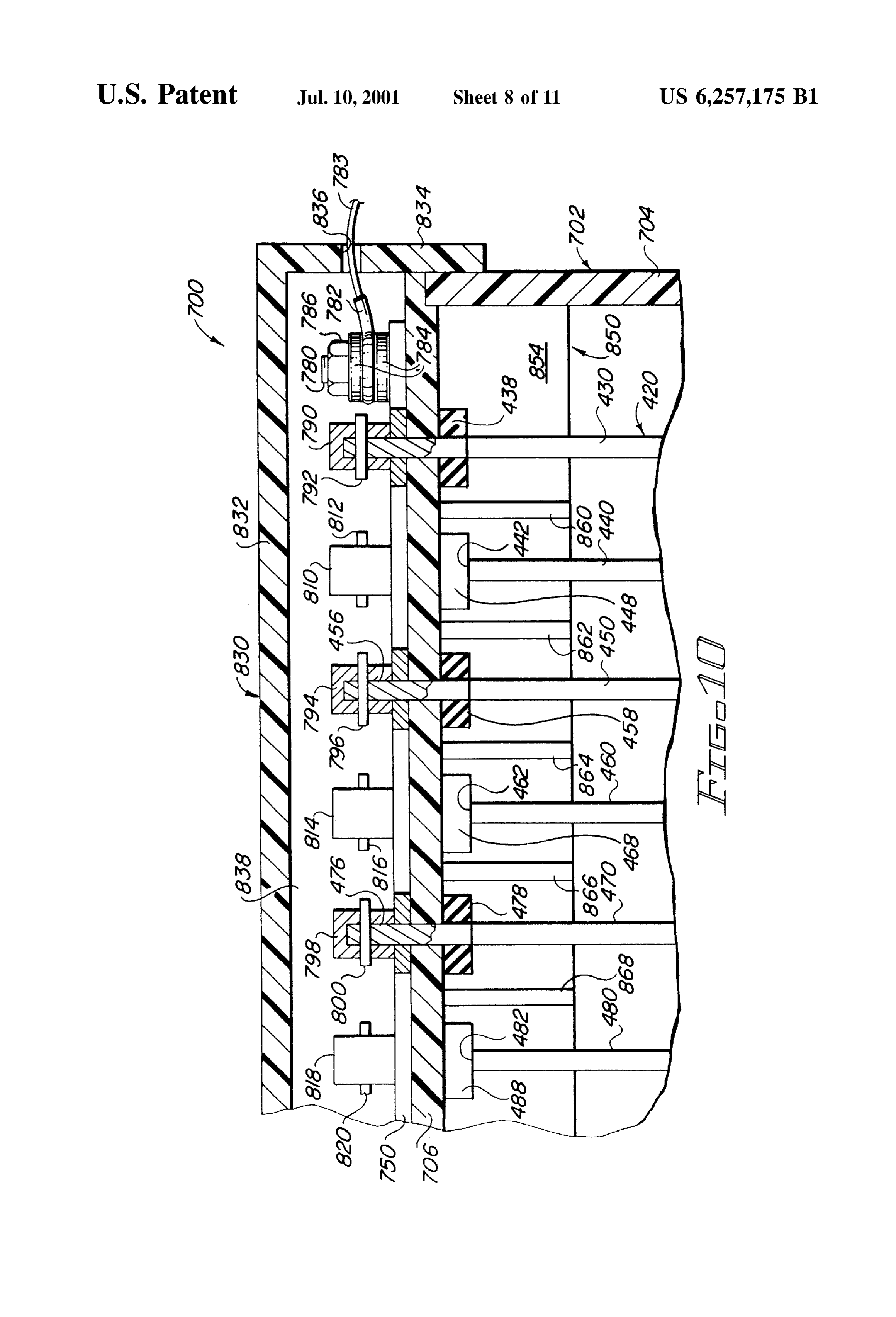
collector plate or electrode plate, into a separate gas gen erator cell. The collector assembly 550 includes a top plate FIG. 10 is a fragmentary front view in partial section of 552, and a plurality of relatively short, but vertically extend another embodiment apparatus 700 of the present invention. ing walls depend from the top wall 552. The apparatus 700 uses the electrode assembly 420 dis In FIG. 9, a rear wall 574 of the collector assembly 550 cussed above with slight variations, primarily in the elec is shown. A front wall, not shown, and a pair of end walls, 15 trical connector elements. In FIG. 10, six plates 430, 440, also not shown, extend downwardly from the top plate or 450, 460, 470, and 480 are shown. The plate array 420 is wall 552 to form the outer perimeter of the collector assem disposed within a housing 702. For purposes of the present bly 550. invention, the housing 702 includes an end wall 704 and a In addition to the four Outer perimeter walls, there are a top wall 706. Extending through the top wall 706 are slots plurality of intermediate walls joined to the front and rear which receive the arms of the plates. Thus, a slot 708 walls and to the top wall. Within the respective walls are receives the upwardly extending arm 436 of the plate 430, collection chambers above the plates. In FIG. 9, intermedi a slot 712 receives the upwardly extending arm 456 of the ate walls 558, 560, 562, 564, and 566, are shown. plate 450, and a slot 17 receives the upwardly extending arm Between the walls 558 and 560, and downwardly from the 476 of the plate 470. There are also slots, not shown, which top wall 552, and between the front wall (not shown) and the 25 receive the upwardly extending arms 446, 466, and 486 of rear wall 574, is a collection chamber 559. A collection the plates 440, 460, and 480, respectively. chamber 561 is defined between the front and rear walls and Gaskets or washers, made of an appropriate material, Such the intermediate walls 560 and 562. A collection chamber as neoprene rubber, provide a Seal between the plates and the 563 is similarly shown between the walls 562 and 564, the top wall 706. The gasket seals include slots through which rear wall 574, and the front wall. A fourth collection cham the arms of the plates extend. The gasket Seals are held ber 565 is shown between the walls 564 and 566, the rear against the bottom surface of the top plate 706 by the top wall 574, and the front wall. edges of the plates.
The upper portion of the respective electrode plates The gasket seals shown in FIG. 10 include a gasket 438 extend into the collection chambers. The upper portion of disposed on the arm of the plate 430, a gasket 448 disposed the plate 450 extends into the collection chamber 559. The 35 on the arm of the plate 440, a gasket 458 disposed on the arm plate 460 extends into the collection chamber 561, the plate of the plate 450, a gasket 468 disposed on the arm of the 470 extends into the collection chamber 563, and the plate plate 460, a gasket 478 disposed on the arm of the plate 470, 480 is shown extending into the collection chamber 565. and a gasket 488 disposed on the arm of the plate 480. Each collection chamber is disposed at the upper portion The gaskets 448, 468, and 488 are shown disposed on the of a collector cell. Each collector cell includes a collector 40 top edges 442, 462, and 482, respectively, of their plates. cell conduit which extend upwardly from the top wall 552 of The gaskets help to prevent any generated gas from leaking the collector assembly 550, and through the top plate 404 of upwardly past the vertical arms and help to prevent any the housing 402. The collector cell conduits include the moisture, water and electrolytes, from also leaking conduits 584,586, 588, and 590, shown in FIGS. 7 and 9, upwardly. Thus, the plates and water and electrolyte are and also conduits 580, 582,592, and 594, shown in FIG. 7. 45 essentially Sealed in the housing. Only the upper portion of (Conduit 586 is not shown in FIG. 7, but is shown in FIG. the vertical arms of the plates extend above the top plate 706 9). for electrical contact purposes. The gases generated on the The conduits 580, 584,588, and 592 extend to a collector plates are isolated, as discussed above, and are collected header 600, and a conduit 602 is secured to the header 600. Separately, as also discussed above. The conduit 602 extends to an engine's intake manifold. The 50 Disposed on the top 706 is a conductive element 750. The conduits 582, 586, 590, and 594 extend to a collection conductive element 750 is shown fragmentarily in plan view header 610, and a conduit 612 is secured to the header 610. in FIG. 11. FIG. 11 comprises a top, plan view of the element The conduit 612 extends from the header 610 to the intake 750, or a portion thereof, which is associated with the plates manifold of the engine. As may be understood from FIGS. 430, 450, and 470 illustrated in FIG. 10. For the following 7 and 8, the terminal 620 is secured to the vertical arm or 55 discussion of the conductive element 750, attention will be post 522. A conductor 622 is in turn connected to the directed to both FIG. 11 and FIG. 10. terminal 620. A similar terminal 630 is secured to the The conductive element 750 is preferably stamped out of vertical arm or post 532, and a conductor 632 is secured to copper, or the like, and is disposed on the top 706, as the terminal 630. The conductor 622 and 632 extend to the discussed above.
appropriate electrical element, one of them, as desired, to a 60 The conductive element 750 includes a strip 752. A Source of positive current and the other to an appropriate plurality of arms or ears extend outwardly from the Strip circuit ground. 752. A slot extends through each arm or ear. The slots Water level 140 is indicated by the dashed line 140 in FIG. receive the upwardly extending arms of the respective 10. It will be noted that the water level 140 is above the top plates. Thus, arms 754, 758, and 762 include, respectively, of the electrode plates within the housing 402. 65 slot 756,760, and 764. The arm 436 extends through the slot The various elements for maintaining the water level at 756, the arm 456 extends through the slot 760, and the arm the desired height within the housing 402 is, of course, well 476 extends through the slot 764.
Page 19
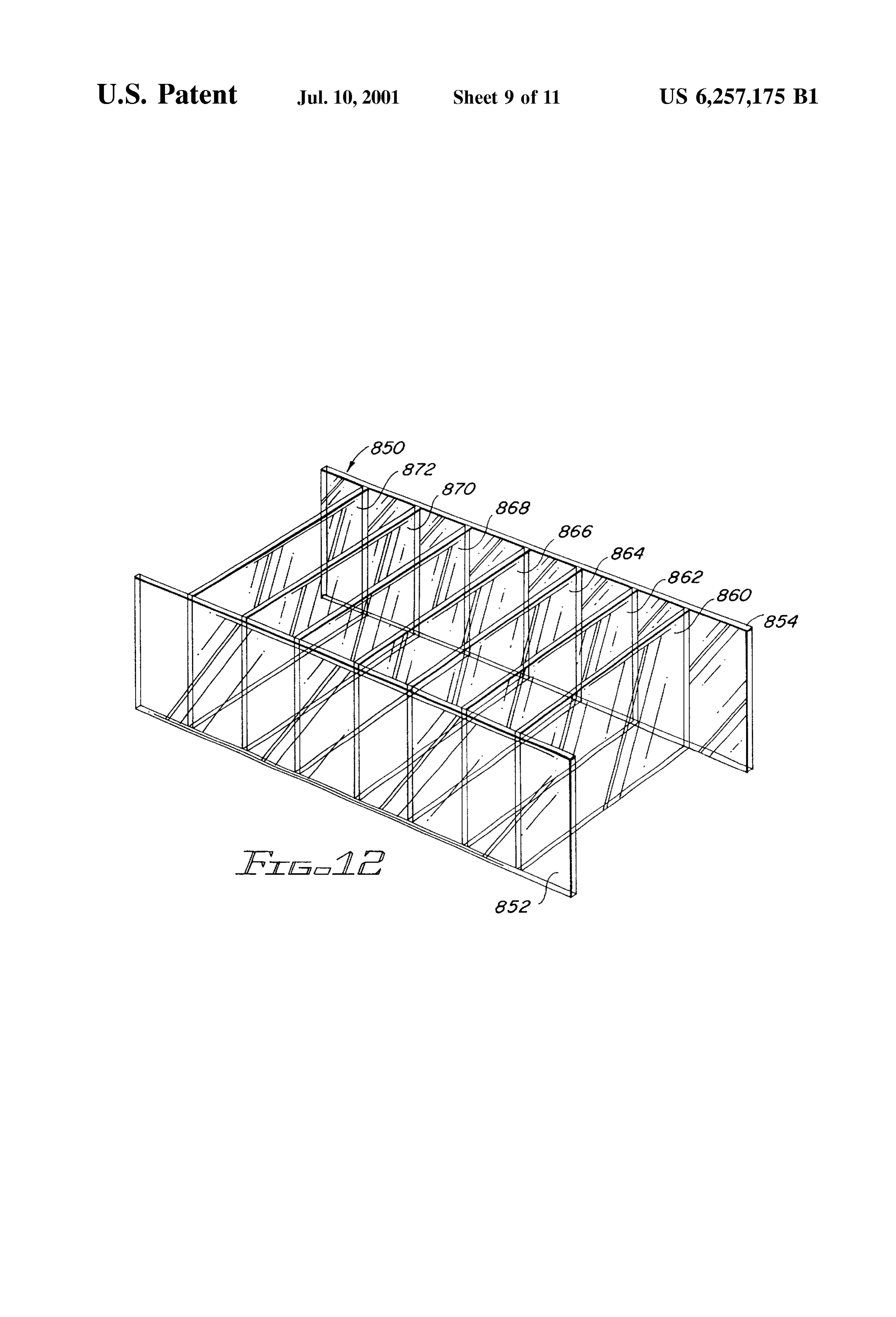
The slots 756, 760, 764, etc., are dimensioned so as to be conductive element is illustrated in FIG. 13 and will be Substantially the same size as the dimensions of the discussed below in conjunction therewith. upwardly extending arms to help provide a good electrical FIG. 12 comprises a perspective view of the alternate contact between the arms and the element 750. embodiment collector assembly 850. The collector assembly Extending upwardly from one end of the strip 752 is a 850 is also illustrated in FIGS. 10 and 13, and reference will post 780. The post 780 is threaded at its upper portion to be made to those Figs. as well as to FIG. 12 for the following receive a nut 786. As shown in FIG. 10, an electrical discussion.
connector 782, with its conductor 783, is appropriately The collector assembly 850 includes a pair of spaced apart secured to the post 780 between a pair of washer elements walls 852 and 854. Seven divider panels 860,862, 864, 866, 784. The nut 786 secures the washer 784 and the connector 868, 870, and 872 extend between and are appropriately 782 to the post 780. secured to the wall panels 852 and 854. The outer ends of the walls 852 and 854 extend into slots in the end walls of a
Attention will now be directed primarily to FIG. 10 again. housing to Support the collector assembly in a housing. In To insure good electrical contact between the arms 436, 456, FIG. 10, one end of the wall 854 is shown disposed in a slot and 476, etc., with the conductive strip 750, caps and pins 15 in the end wall 704 of the housing 702. are used. In FIG. 8, it will be understood that the upwardly The collector assembly 850 extends downwardly from a extending arms each have holes or apertures extending top plate of a housing and covers the upper portion of an through them for receiving the rods 520 and 530, as appro eight plate assembly, such as the plate assembly 420 of FIG. priate. In the embodiment of FIGS. 10 and 11, pins extend 8. The panels and the walls 852 and 854 divide the assembly through the holes in the arms to Secure the caps to the arms. 850 into eight of collector cells, or one collector cell for each The caps extend downwardly and bear against the ears of the electrode palate in the plate assembly 420 of FIGS. 10 and conductive element 750. 13. The end walls of the housing 702 comprise the end walls The upper portion of the arm 436 of the plate 430 is for the outer two collector cells.
covered by a cap 790. A pin 792 extends through both the The assembly 850 is preferably injection molded. The cap 790 and the arm 436. A similar cap 794 with its pin 796 25 assembly 850 is, of course, made of appropriate noncon is disposed on the top of and secured to the arm 456 of the ductive material impervious to the chemicals and chemical reactions involved in the generation of the hydrogen and plate 450. A cap 798 is shown disposed on the upper portion OXygen of the arm 476 of the plate 470, and a pin 800 extends gases.
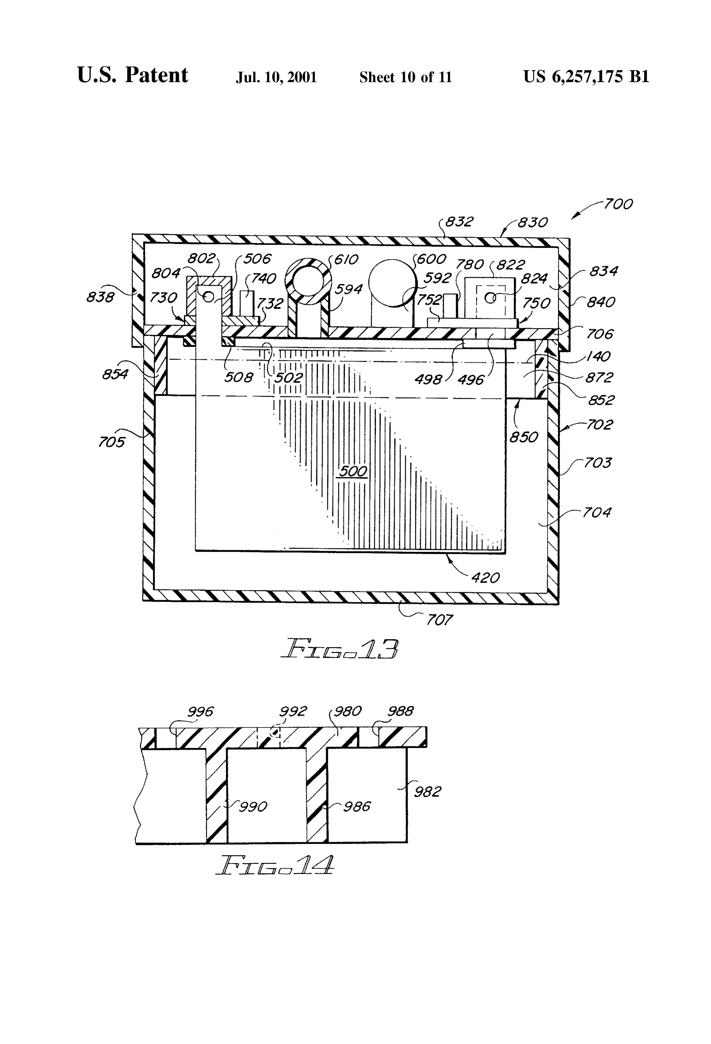
through both the cap 798 and the arm 476. FIG. 13 is a view in partial section of the apparatus 700 Caps and pins are also shown associated with the arms of FIG. 10, and specifically an end view with the end wall 446, 466, and 486. The arm 446 is shown with a cap 810 opposite to the wall 704 of FIG. 10 removed, illustrating disposed thereon, and a pin 812 extends through both of Some of the various elements involved in the apparatus 700 them. A cap 814 and a pin 816 are shown in conjunction with 10. Thedifferent from a point of reference from that shown in FIG.
collector assembly 850 is shown within the housing the arm 466 of the plate 460. Finally, a cap 818 with its pin 702, extending downwardly from the top wall 706 of the 820 are shown in conjunction with the arm 486 of the plate 35 housing 702.
480. The housing 702 includes a pair of side walls 703 and 705, The connector 782 is disposed between a pair of washers and a bottom wall 707. The end wall 704 is also shown in 784 on the post 780 and is held thereon by a nut 786. FIG. 13. The side walls 852 and 854 extend into slots in the Also shown in FIG. 10 is a non-conductive top cover 830 end wall 704, as shown in FIG. 10 for the side wall 854, and which encloses the electrical elements and also the gas 40 into aligned slots in the opposite end wall, not shown. manifolds, not shown in FIG. 10, to thus provide a degree of On the upper surface of the top wall 706 are two con protection for the entire apparatus 700. The cover 830 ductive elements, the conductive element 750, discussed includes, as illustrated in FIG. 10, a top wall 832, an end wall above, and a conductive element 730. The element 730 is 834, and a side wall 838. The cover is appropriately secured substantially identical to the element 750, except that the to the housing 702. An aperture in the end wall 836 receives 45 element 730 is the mirror image of the element 750. The the conductor 783. Other apertures extending through the element 730 includes a strip 732 and a plurality of ears or walls of the cover 830 receive the two conduits for the gases arms extend outwardly from the strip 730 for electrically generated in the apparatus 700 and also a Second conductor contacting the upwardly extending arms of the plates of the for the electrical System. electrode plate assembly 420.
A collector assembly 850 is also shown in FIG. 10. The 50 Of the electrode assembly 420, a plate 500 is shown, with collector assembly 850 is also shown in FIG. 12 and is its arm 506 extending upwardly through an aperture in the discussed in detail in conjunction there with. The collector top wall 706, and extending through an aperture in an ear or assembly 850 is also shown in FIG. 13. The collector arm of the conductive strip 732 of the conductive element assembly 850 is shown in partial section from two different 730. A seal or gasket 508 is shown disposed about the arm points of reference in FIGS. 10 and 13. The assembly 850 is 55 506 between the top wall 706 and the top edge 502. The post shown in perspective in FIG. 12. 740 is shown extending upwardly from the strip 732. It will be noted that the conduits and manifolds associated A cap 802 is shown disposed over the arm 506, and a pin with the collector assembly 850 and the plate assembly 420 804 is shown extending through both the arm 506 and the and through which the generated gas flows have been cap 802. The cap 802 provides electrical contact with both omitted from FIG. 10 for purposes of clarity. Some of those 60 the arm 506 and the arm portion of the conductive element elements are illustrated in FIG. 13 and similar structure is 750 through the ear portion of the conductive element 750 also shown in FIGS. 7 and 9. Again, such elements have through which the arm 506 extends. The post 780 is shown been omitted for purposes of clarity. extending upwardly from the strip 752 of the conductive Also, as indicated above, a conductive element, Such as element 750.
the element 750, will also be utilized for electrically con 65 An arm 496 of the plate 490 is also shown extending necting the plates 440, 460,480, and their upwardly extend through a slot in the top wall 706. A seal or gasket 498 is ing arms, including a post, the electrical connector, etc. Such shown disposed about the arm 496 at the top wall 706.
Page 20
A cap 822 is shown disposed over the upper portion of the 942, depending on the direction of flow, and to ultimately, arm 496, and a pin 824 is shown extending through both the the intake manifold of an engine. The apparatus 900 essen cap 822 and the arm 496. The cap 822 is thus in electrical tially works the same as discussed above, although the contact with both the arm 496 and the ear of the connective structure is different. The use of the relatively flat plate 920 element 750 through which the arm 496 extends. may be advantageous when the Space available for a hydro Of the collector assembly 850, the walls 852 and 854 are but gen and oxygen generating apparatus is relatively narrow shown in FIG. 13, and a panel 872 is shown extending rather long.
between the walls 852 and 854, and downwardly from the FIG. An alternate embodiment of the plate 920 is illustrated in top wall 706. 16. FIG. 16 comprises a side view in partial section of an alternate
The conduit 594 is shown extending upwardly above the tially an inverted electrode assembly 950, which includes essen “U” shaped element.
plate 500 and through the top wall 706. The conduit 594 The electrode assembly 950 includes a base 952 through extends to the header 610. The conduit 592 is shown which extends an aperture 954. Extending downwardly from extending to the header 600. The hydrogen gas generated at the outer ends of the base 952 are a pair of arms 956 and 958. the plate 500 will accordingly flow through the conduit 594 15 Extending through the aperture 954, and appropriately into the header 610, and the oxygen generated at the plate welded to the base 952, is the lower or bottom end of a pipe 490, whose arm 496 is shown in FIG. 13, will flow through 960. The upper part of the pipe 960 includes a portion 962. the conduit 592 and into the header 600. The portion 962 makes contact with an appropriate collector The space between the bottom of the plate 500 (and, of for the gas generated by the electrode assembly 950. course, the other plates in the assembly 420) and the bottom A plurality of apertures 964 extend through the pipe 960. wall 707 provides ample clearance for any sediment that The gases then flow upwardly in the inside of the pipe 960. falls to the bottom wall 707. The clearance prevents, or at The bottom end of the pipe 960 is open, and gases generated least minimizes, the likelihood of Sediment building up on or forming on the interior of the arms 956 and 958, and the the bottom 707 and shorting out the plates in the assembly bottom of the arm 952, will flow upwardly into the pipe 960 420. through the open bottom end.
The level of the water (and electrolyte), is shown in 25 The electrode apparatus 950 may also be used when the dashed line and is indicated by reference numeral 140. It will Space available for a hydrogen and oxygen generating be noted that the water level 140 is well above the bottom apparatus is relatively long and relatively narrow. The height of the collector assembly 850. (or length) of the arms 956 and 958, and their width, may, The cap 830 is shown disposed over the headers 600 and of course, vary, depending on the Surface area desired. It will 610 and the electrical elements, all of which are disposed on be noted that the Surface area on which the gas is generated the top wall 706. The top 832 end wall 834, side wall 838 is substantially greater for the electrode 950 than for the are shown in FIG. 13, and also a second side wall 840. The plate 920 and its pipe.
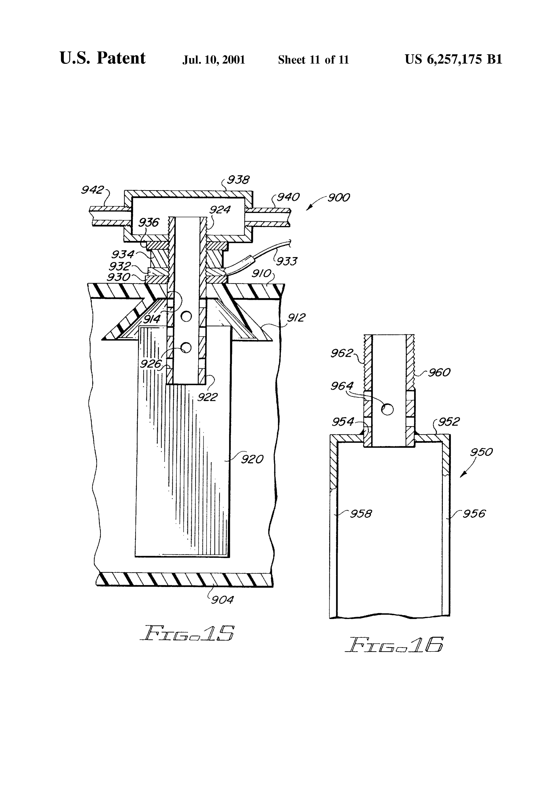
cap 830 comprises a cover, as indicated above, for the Two embodiments of collector assemblies are illustrated housing 702 and the elements disposed on the top plate 706. 35 in FIG. 9 and in FIGS. 10, 12, and 13. In FIG.9, the collector FIG. 15 comprises a fragmentary view in partial Section assembly 550 is shown with a top 552 and a plurality of of an alternate View in partial Section of an alternate embodi panels extending downwardly from the top 552 and between ment 900 of the apparatus of the present invention. The a pair of side walls or panels, of which the panel or wall 574 apparatus 900 includes a flat plate electrode 920, as opposed is shown. The assembly 550 extends downwardly from the to the other electrode elements discussed above in conjunc 40 top wall 404 of the housing 402 in FIG. 9. tion with the various embodiments. In FIGS. 10, 12, and 13, the collector assembly 850 is The apparatus 900 includes a housing, including a bottom shown. The collector assembly includes only a pair of walls plate 904, and a top plate or cover 910. Extending down 852 and 854 with a plurality of panels extending between the wardly and outwardly from the housing top or cover 910 is walls. The assembly 850 abuts the top wall 706 of the an integral collector cone 912. Centrally disposed within the 45 housing 702 in FIG. 10.
collector cone 912 is an aperture 914. Extending through the A third embodiment of a collector assembly is shown in aperture 914 is a pipe 922. The pipe 922 is appropriately FIG. 14. FIG. 14 is a fragmentary view of a portion of a top Secured, as by welding, to the plate 920. Extending through wall 980, showing the collector assembly as an integral part the pipe 922 are apertures 926 through which generated gas of the top wall. A side wall 982 and two divider panels 986 flows into the pipe 922 and upwardly therethrough. The pipe 50 and 990 of the collector assembly are shown extending 922 and the plate 920 are preferably made of titanium, etc. downwardly from the top wall 980 and outwardly from the or Some other appropriate corrosive resistant metal. wall 982 to a second side wall, not shown. Apertures for At the upper or top part of the pipe 922 is a threaded receiving conduits for collecting gases generated at plates portion 924. The threaded portion 924 matingly engages the extend through the top wall 980 between the divider panels. internal threads of a collector element 938. Between the 55 An aperture 988 extends between the panel 986 and the wall collector element 938 and the top plate or cover 910 is a (not shown) of the housing on which the top wall is washer or gasket 930, a electrical connector 932 from which disposed, as, for example, the end wall 704 of the housing extends a connector 933, and a nut 934. Above the nut 934, 702 of FIG. 10 and FIG. 13. An aperture 992 is shown in and bearing against the bottom of the collector 938, is dashed line between the panels 986 and 990. An aperture another washer or gasket 936. Extending outwardly from the 60 996 is shown between the panel 990 and its next adjacent collector 938 are connector tubing elements 940 and 942. panel, not shown.
In operation, gas, either hydrogen or oxygen, depending Each of the three embodiments has its own advantages on the polarity of the electrical connector 932, is generated and disadvantages. A collector assembly is used in conjunc at the plate 920 and at the pipe 922. The generated or tion with a relatively large System, Such as when a plate liberated gas flows upwardly, and into the pipe 924 through 65 assembly is used. A collector assembly is, of course, not the aperture 926 and upwardly into the collector 938. The needed when electrodes, such as shown in FIGS. 2, 3, 4, 5, gas then flows through either the conduit 940 or the conduit 6, 14, and 15 are used.
Page 21
The Selection of a particular electrode type depends 2. The apparatus of claim 1 which further includes an primarily on the quantity of hydrogen and oxygen desired. electrolyte in the quantity of water. The quantity, in turn, depends on the Size of engine involved. 3. The apparatus of claim 1 which the electric current Moreover, Space limitations and electrical needs are also means is connected to the electrical System of the vehicle considerations. through the ignition circuit to insure that oxygen and hydro In all of the embodiments discussed herein, the two gases gen4.are The generated only when the ignition circuit is energized.
apparatus of claim 3 in which the electric current are kept Separated from each other and are collected Sepa rately. The gases are also conveyed to the intake manifold means includes means for Sensing the water level in the case Separately, and accordingly are not mingled until they flow and a Switch for disconnecting the electric current to the anode and cathode when the water level in the housing drops to the respective cylinders of the engine in the vehicle in below a predetermined level.
which they are Secured, as discussed above. 5. The apparatus of claim 3 in which the electric current This Separate collection cell System in which the gases are means includes means for Sensing a flow of air in the intake collected Separately and maintained separately offerS Sub manifold and Switch means for disconnecting the electric Stantial Safety considerations over hydrogen and oxygen 15 current to the anode and cathode in response to the cessation generator apparatus in which the gases are collected together of the flow of air in the intake manifold. and are transported together. 6. The apparatus of claim 3 in which the electrical current Electrolytes for the electrolysis reactions in generating of means further includes an ammeter for measuring the flow electric current between the anode and the cathode.
hydrogen and oxygen are well known and understood in the 7. The apparatus of claim 1 which further includes a art. Typically, acids may be used or bases, Such as Sodium reservoir for holding a replenishing Supply of water for the hydroxide or potassium hydroxide, etc. Depending on the CSC.
current densities required, or desired, either a basic electro 8. The apparatus of claim 7 in which the housing means lyte Solution or an acidic electrolyte Solution may be used. further includes a water conduit extending between the For electrodes, as Stated, an appropriate metal will be reservoir and the case through which replenishing water used. For most applications, titanium may be most Suitable. 25 flows from the reservoir to the case. Stainless steel or other metals or alloys may be suitable for 9. The apparatus of claim 8 in which the housing means other applications. further includes means for Sensing the level of the water in While the principles of the invention have been made the case and valve means for controlling the flow of replen clear in illustrative embodiments, there will be immediately ishing water in the water conduit.
obvious to those skilled in the art many modifications of 10. The apparatus of claim 1 in which the anode and the Structure, arrangement, proportions, the elements, materials, cathode each comprise a plurality of plates Spaced apart and components used in the practice of the invention, and from each other and interleaved in the case. otherwise, which are particularly adapted to Specific envi 11. The apparatus of claim 10 in which the first conduit ronments and operative requirements without departing means includes first collection means for collecting the from those principles. For example, while the present appa 35 oxygen generated at each plate of the plurality of anode ratus has been discussed in terms of a vehicle and an engine plates and a first conduit extending from the first connection in the vehicle, it is obvious that the apparatus may also be means to the intake manifold through which the oxygen used in conjunction with a Stationary engine. The appended flows.
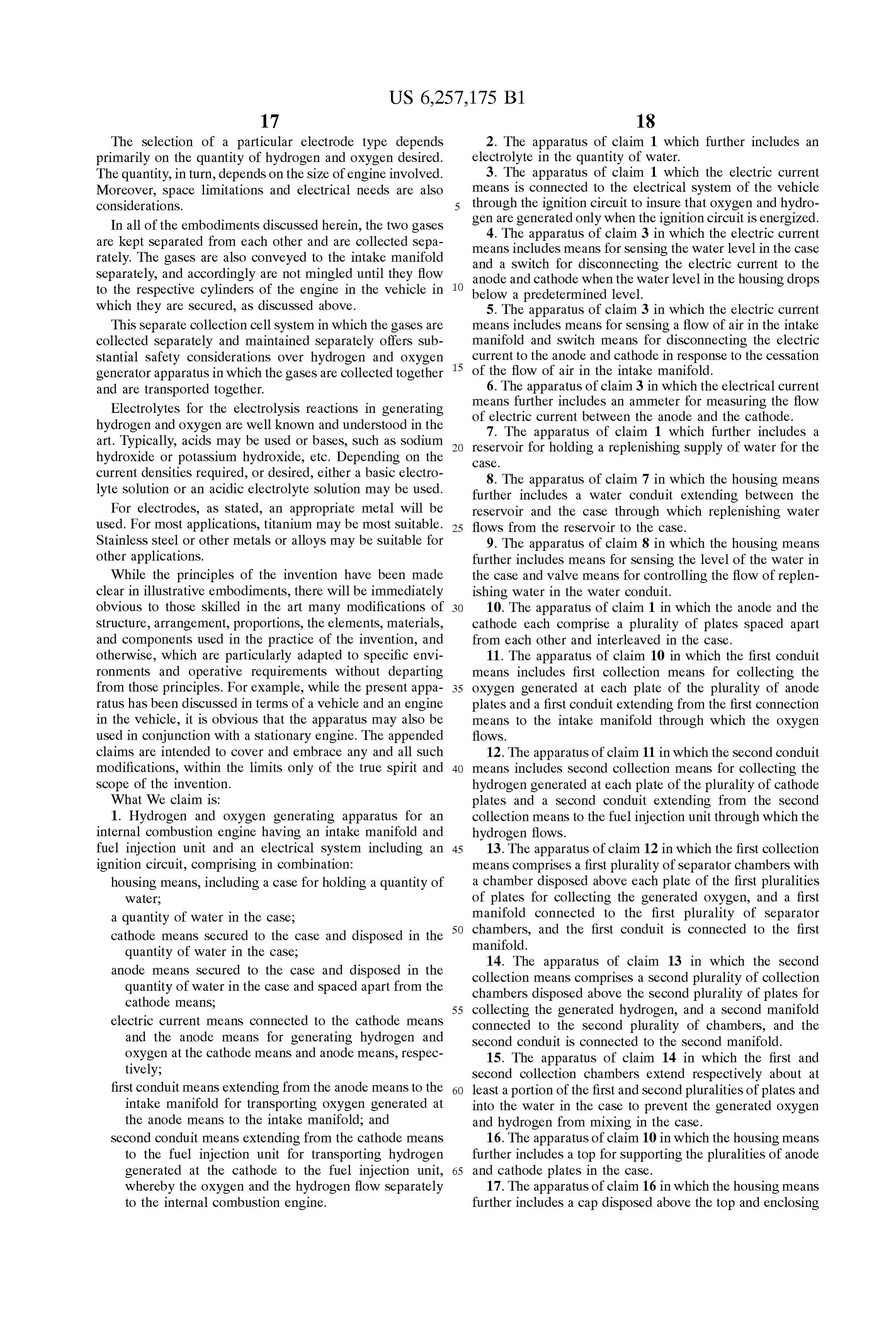
claims are intended to cover and embrace any and all Such 12. The apparatus of claim 11 in which the second conduit modifications, within the limits only of the true spirit and 40 means includes Second collection means for collecting the Scope of the invention. hydrogen generated at each plate of the plurality of cathode What We claim is: plates and a Second conduit extending from the Second 1. Hydrogen and oxygen generating apparatus for an collection means to the fuel injection unit through which the internal combustion engine having an intake manifold and hydrogen flows.
fuel injection unit and an electrical System including an 45 13. The apparatus of claim 12 in which the first collection ignition circuit, comprising in combination: means comprises a first plurality of Separator chambers with housing means, including a case for holding a quantity of a chamber disposed above each plate of the first pluralities Water, of plates for collecting the generated oxygen, and a first a quantity of water in the case, manifold connected to the first plurality of Separator 50 chambers, and the first conduit is connected to the first cathode means Secured to the case and disposed in the manifold.
quantity of water in the case, anode means Secured to the case and disposed in the collection 14. The apparatus of claim 13 in which the second quantity of water in the case and Spaced apart from the chambers disposedmeans comprises a Second plurality of collection cathode means, above the Second plurality of plates for 55 collecting the generated hydrogen, and a Second manifold electric current means connected to the cathode means connected to the Second plurality of chambers, and the and the anode means for generating hydrogen and Second conduit is connected to the Second manifold. oxygen at the cathode means and anode means, respec 15. The apparatus of claim 14 in which the first and tively; Second collection chambers extend respectively about at first conduit means extending from the anode means to the 60 least a portion of the first and Second pluralities of plates and intake manifold for transporting oxygen generated at into the water in the case to prevent the generated oxygen the anode means to the intake manifold; and and hydrogen from mixing in the case.
Second conduit means extending from the cathode means 16. The apparatus of claim 10 in which the housing means to the fuel injection unit for transporting hydrogen further includes a top for Supporting the pluralities of anode generated at the cathode to the fuel injection unit, 65 and cathode plates in the case.
whereby the oxygen and the hydrogen flow Separately 17. The apparatus of claim 16 in which the housing means to the internal combustion engine. further includes a cap disposed above the top and enclosing
Page 22
at least a portion of the electric current means, the first 27. The apparatus of claim 26 in which the first collector conduit means, and the Second conduit means. and the Second collector are made of nonconductive mate 18. The apparatus of claim 1 in which the anode means rial.
and the cathode means each include a pipe, and a plurality 28. The apparatus of claim 26 which further includes of apertures extend through each pipe. conductive sleeves disposed about and Secured to the first 19. The apparatus of claim 18 in which the anode means and Second pipes.
and the cathode means further include a Square tube dis 29. The apparatus of claim 28 in which the conductive posed about each pipe, and a plurality of apertures extends sleeves include a plurality of apertures extending through through each tube.
20. The apparatus of claim 19 in which each pipe is in 1O them and through which the water and electrolyte flows. electrical contact with its tube, and the plurality of apertures SecondThe 30. apparatus of claim 26 in which the first and collectors further include first and Second skirts in the tubes are aligned with the apertures in the pipes.
21. The apparatus of claim 20 in which the anode means Secured insure to the first and Second collectors, respectively, to that the generated gases flow upwardly into the pipes.
and the cathode means further include a Zinc bar Secured to and disposed against each tube. 15 31. A method of generating oxygen and hydrogen for an 22. The apparatus of claim 18 in which the anode means internal combustion engine comprising the Steps of and the cathode means each include a plate Secured to a pipe. providing a housing;
23. The apparatus of claim 22 in which each pipe includes providing a quantity of water in the housing, a plurality of apertures extending through the pipe through providing an anode electrode and a cathode electrode in which water and electrolyte and the generated gas flows. the quantity of water;
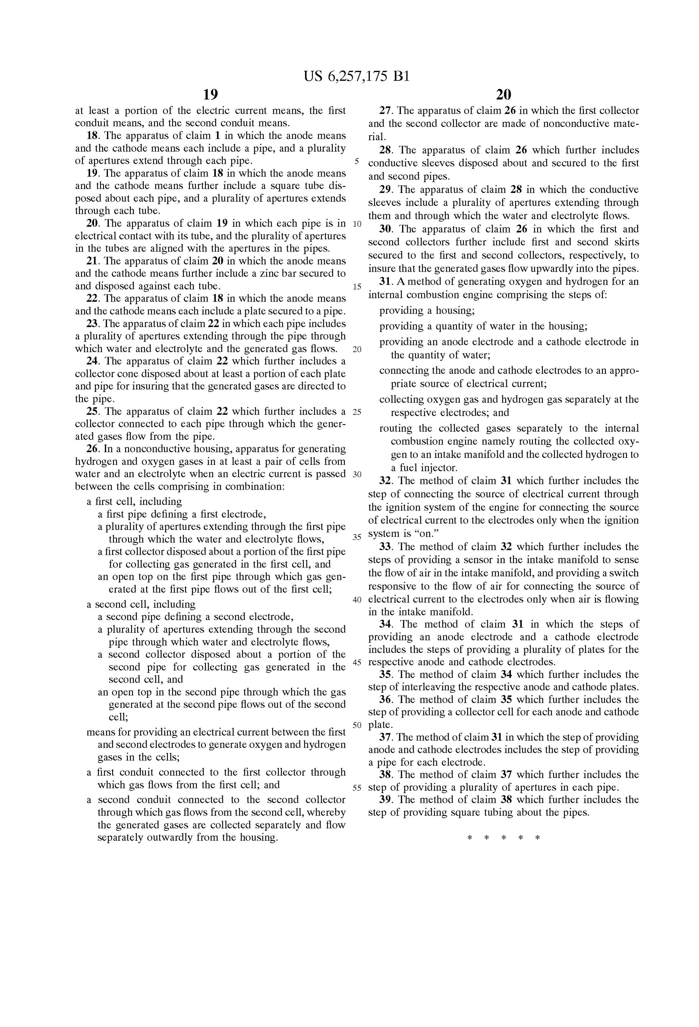
24. The apparatus of claim 22 which further includes a collector cone disposed about at least a portion of each plate connecting the anode and cathode electrodes to an appro and pipe for insuring that the generated gases are directed to priate Source of electrical current; the pipe. collecting oxygen gas and hydrogen gas Separately at the 25. The apparatus of claim 22 which further includes a 25 respective electrodes, and collector connected to each pipe through which the gener routing the collected gases Separately to the internal ated gases flow from the pipe. combustion engine namely routing the collected oxy 26. In a nonconductive housing, apparatus for generating gen to an intake manifold and the collected hydrogen to hydrogen and oxygen gases in at least a pair of cells from a fuel injector.
water and an electrolyte when an electric current is passed 32. The method of claim 31 which further includes the between the cells comprising in combination: Step of connecting the Source of electrical current through a first cell, including the ignition System of the engine for connecting the Source a first pipe defining a first electrode, a plurality of apertures extending through the first pipe of electrical current to the electrodes only when the ignition system is “on.” through which the water and electrolyte flows, 35 33. The method of claim 32 which further includes the a first collector disposed about a portion of the first pipe for collecting gas generated in the first cell, and Steps of providing a Sensor in the intake manifold to Sense an open top on the first pipe through which gas gen the flow of air in the intake manifold, and providing a Switch erated at the first pipe flows out of the first cell; responsive to the flow of air for connecting the Source of 40 electrical current to the electrodes only when air is flowing a Second cell, including in the intake manifold.
a Second pipe defining a Second electrode, a plurality of apertures extending through the Second 34. The method of claim 31 in which the steps of pipe through which water and electrolyte flows, providing an anode electrode and a cathode electrode a Second collector disposed about a portion of the 45 includes the Steps of providing a plurality of plates for the Second pipe for collecting gas generated in the respective anode and cathode electrodes.
35. The method of claim 34 which further includes the
Second cell, and Step of interleaving the respective anode and cathode plates. an open top in the Second pipe through which the gas 36. The method of claim 35 which further includes the generated at the Second pipe flows out of the Second Step of providing a collector cell for each anode and cathode cell; 50 plate.
means for providing an electrical current between the first 37. The method of claim 31 in which the step of providing and Second electrodes to generate oxygen and hydrogen anode and cathode electrodes includes the Step of providing gases in the cells, a pipe for each electrode.
a first conduit connected to the first collector through 38. The method of claim 37 which further includes the which gas flows from the first cell; and 55 Step of providing a plurality of apertures in each pipe. a Second conduit connected to the Second collector 39. The method of claim 38 which further includes the through which gas flows from the Second cell, whereby Step of providing Square tubing about the pipes. the generated gases are collected Separately and flow
Separately outwardly from the housing. k k k k k
Provenance
- Collection
- Cited prior art
- Original PDF
- patentimages.storage.googleapis.com →
- Filed
- 1999-05-08
- Pages
- 22
- Method
- pdftotext (the PDF's own text layer) + pdftoppm 300dpi page scans
- Source
- Google Patents bibliographic record
- Granted
- 2001-07-10
- Inventors
- Edward G. Mosher; John T. Webster
- Transcribed from
- patentimages.storage.googleapis.com →